Then I already procured myself the first profiles for the building of platforms, with which it could to start then shortly.
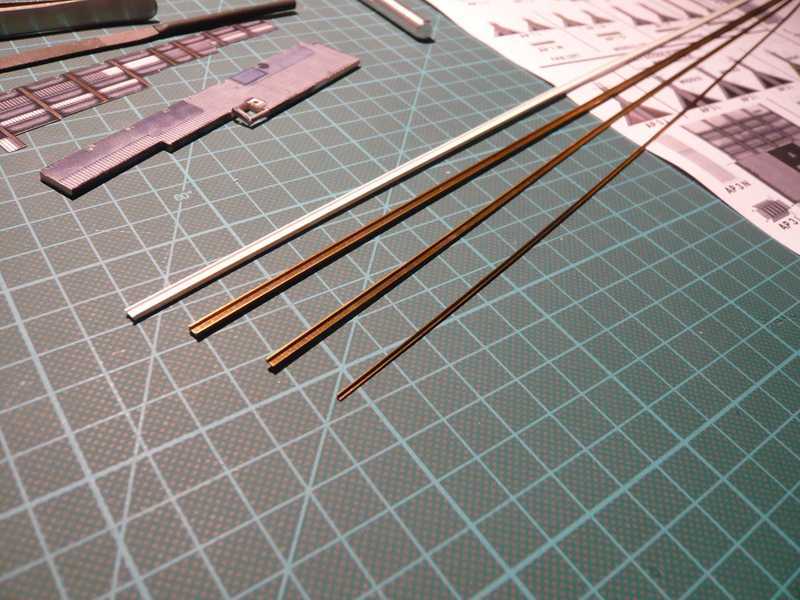
Those are from top to bottom:
I-beam section 3x1,5 mm plastic
I-beam section 2,5x1,5 mm brass
L-section 2x1 mm brass
Angle profile 1x1 mm brass
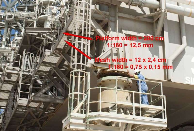
For the gratings I will use now fine-mesh PE plates from brass. Therefor I have estimated the mesh size of the gratings on the basis this and other photos roughly as follows:
 Source: NASA
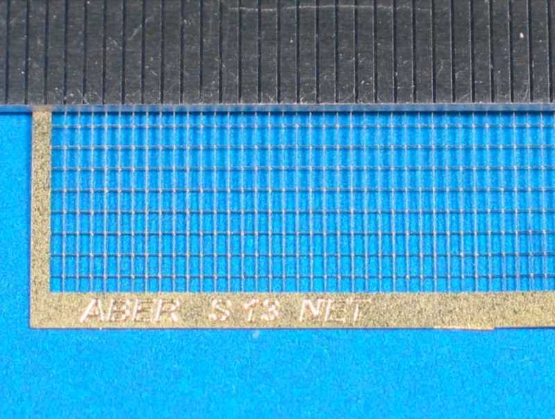
Thus the mesh size should amount to therefore in the original 12.0x2.4 cm and in 1:160 0.75x0.15 mm. Since however so fine-mesh PE plates are offered by no manufacturer, I decided then for a mesh width of 1.2x0.7 mm, which corresponds to the original at least in 2nd approximation.
Therefore I selected now and ordered gratings with 1.2x0.7 mm of mesh size of the Polish company ABER, for which I wait now.
 Source: McM Marketing
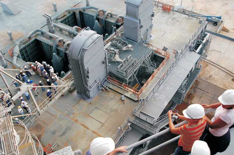
So that it precedes nevertheless, I turned, i.e. now to another important equipment of the MLP the two
Tail Service Masts (TSM). Those are the box-like things to both sides of the SSME exhaust hole, by whose interfaces the shuttle is connected with the MLP. Over it all important supply lines and connections run, via which the shuttle stack is supplied with all necessary media (energy, fuels, data etc.), which are needed during the mission.
 Source: NASA
The TSM parts look on the kit sheet in such a way:
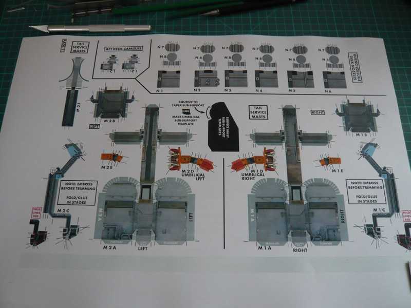
Although both TSM's from the outside form look almost alike, they differ nevertheless in some details, which will still have to be seen. I began first with the right TSM, by which the pipe for the liquid oxygen (LO2) runs.
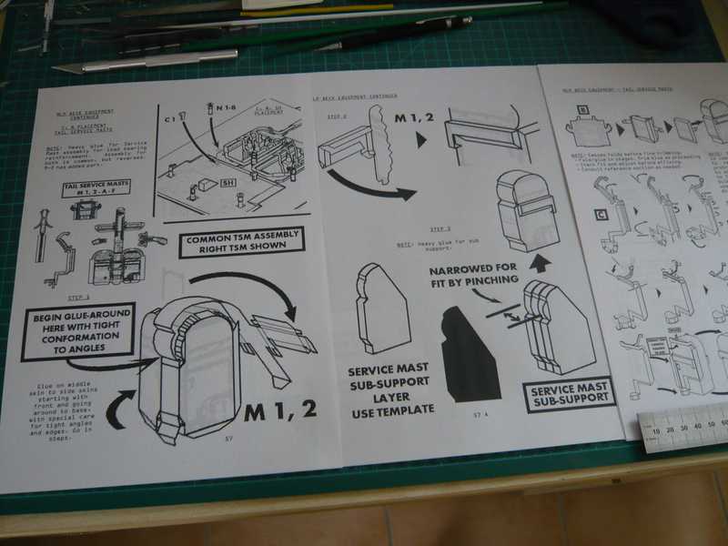
In the building guidance all steps are in detail illustrated.
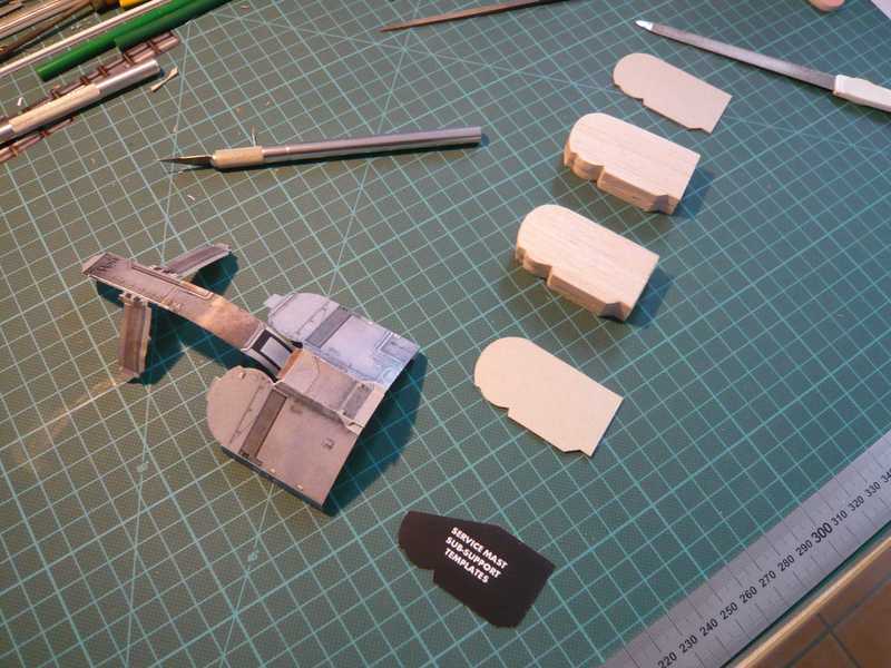
First again reinforcement pieces for the two TSM bases had to be made, to which I had used Balsa and cardboard in proven way again, in order to come on the necessary strength. However the template of the paper kit (black) proved as too inaccurate and/or useless.
In the next step the cores were glued into the paper covering.
In front of the TSM lies one of the two opening flaps with the Balsa reinforcement, which must be glued still in each case on the dark strips on front site and back.
And in such a way the base of the TSM looks then:
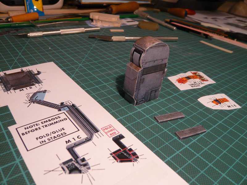
The two opening flaps are not glued to yet, since only still the larger cover (M1B on the sheet above) must to the left TSM side to, which projects laterally, to which then the opening flaps directly attaches.
The bizarre thing (M1C) in the center are parts of the pipings, which I will however not build of paper, because as a too reckless exercise appears to me, whose failing I would like itself to save gladly. That can be made surely more elegant from plastic profiles and wire, thinks I times.
The orange parts right beside the TSM are to show one the plug , whereby I do not realize myself however yet whether I will build those. Thus I must anyway still wait, until that will be finished shuttle (1:144), in order to see whether it would then still fit between them.
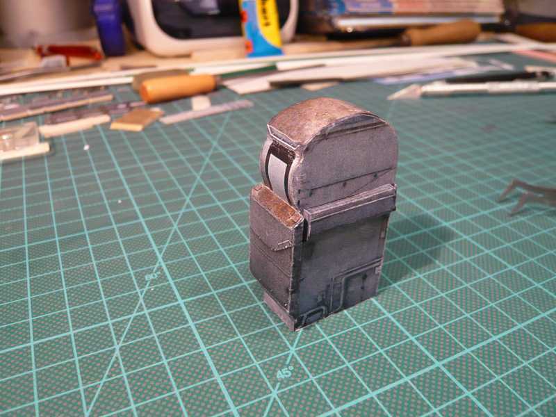
Here however first again the first TSM, still without decorating details such as pipings, cable, ports, etc., but at least already with the opening flaps in front and in the back as well as with the lateral cover to SSME chamber.
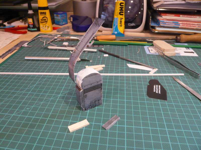
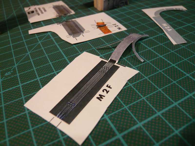
[IMG]The next picture shows the preparations for the second TSM:[/IMG]
Then there is a small difference in form of a curved hood, which pulls itself over the TSM curvature to consider with this TSM.
This curved hood (M2F) exhibits a lamellar extension, which is a Cable Tray according to D. Maier's kit.
So long!
