Hello everybody,
and now to the
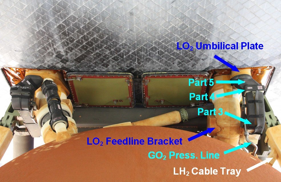
LO2 Cable Tray along with the
TPS Segments at the transition to the
LO2 Umbilical Plate.

As always, before the
Scratch-building of assemblies and parts there is nothing like a thorough inventory and accurate detailed analysis.

...

...

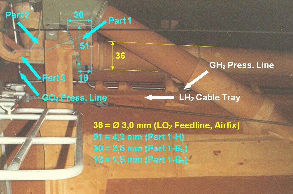
The beginning is again this photo for a better orientation, which helped me because of the direct side view already in the sizing of the
Distribution box, on which I have marked the first three parts of this
LO2 Umbilical assembly.
Directly behind the distribution box is with the
Part 1 a trapezoidal support part whose dimensions (length L, and upper and lower width) I've determined by reference to the diameter of the
LO2 Feedline (Ø 3 mm).

 Source: georgesrockets.com (George Gassaway)
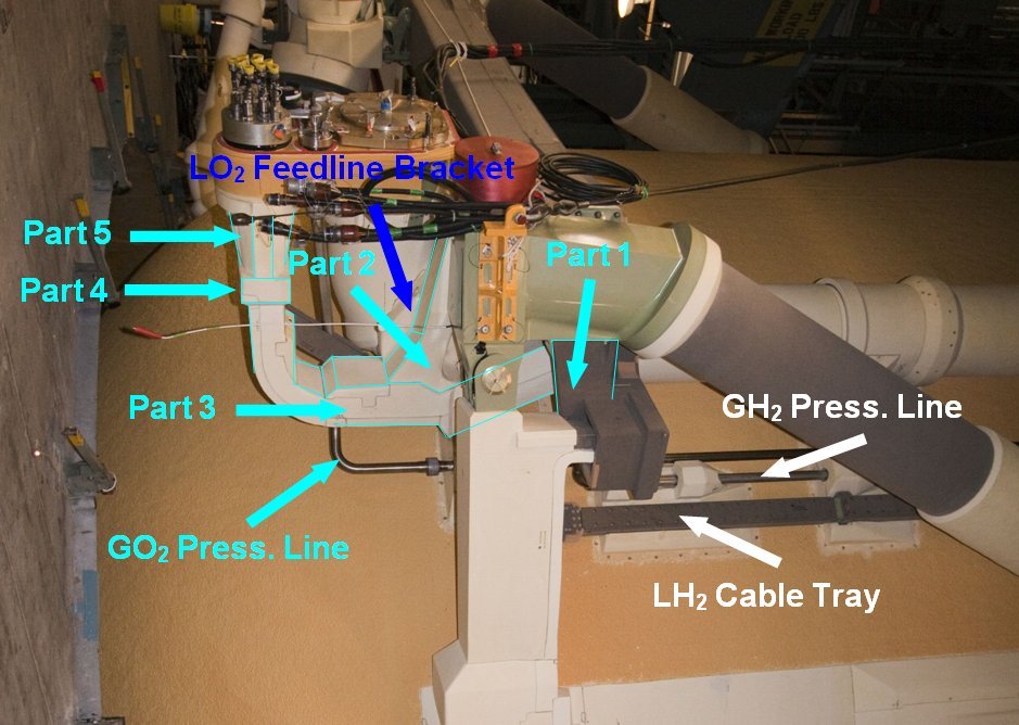
On this rotated photo, one can see this here gray part a bit closer, whereby the linked original zoom is unfortunately rotated.

 Source: forum.nasaspaceflight.com (DaveS)
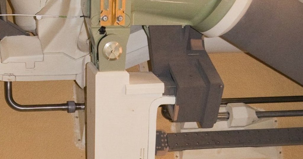
Therefore, here's still a section in original resolution, on which one can see that this part is directly connected with the
Distribution box and with the
LH2 Cable Tray.

And directly behind the oblique branch (
Part 3) runs from the
Cable Tray, which is connected with the
Part 2 and passes over the
Parts 4/5 to the
Umbilical plate.
Thus, only the width of the part is missing, which I have determined from this photo, which allows me to scratch the
Part 1.
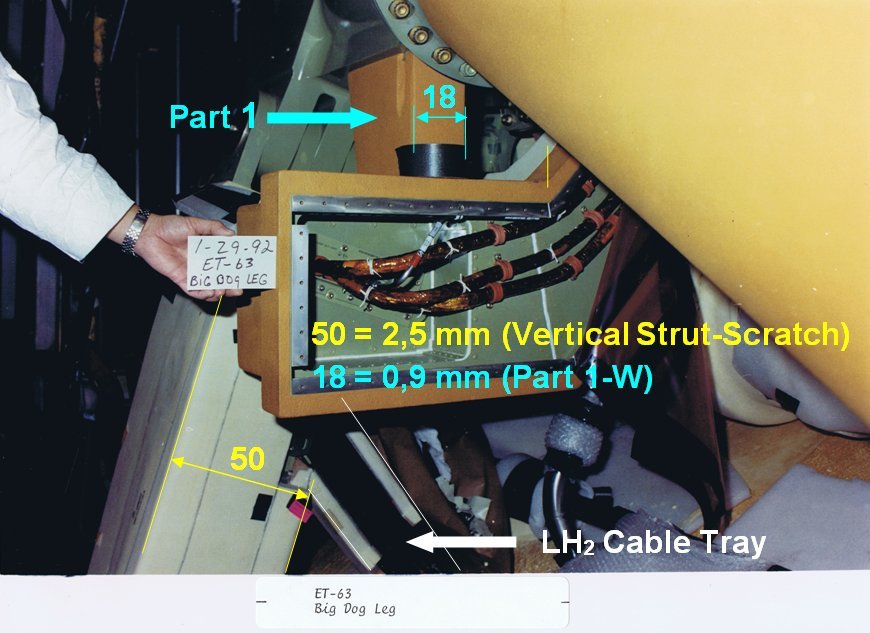
In this picture one can see the cables coming out of the vertical strut, of which one part, as just described, runs up to the
LO2 Umbilical plate and the remainder to the
LH2 Umbilical plate.
In this rear view, the
Parts 3-5 are admittedly covered by cuffs, but one can nicely see the entrance of the
LH2 Cable Tray into the
Vertical Strut.

And in this order, I will now try to scratch these five parts step by step.

