Hello everybody,
and now to the
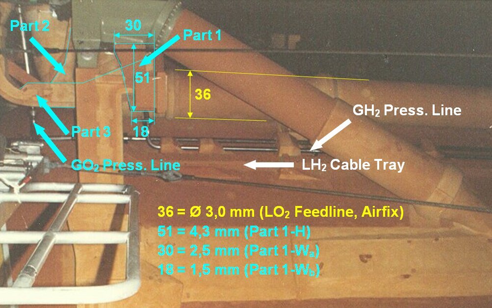
Part 1, which is small, but looks relatively simple, although in this image it is half hidden by the
Distribution box.
 Source: georgesrockets.com (George Gassaway)
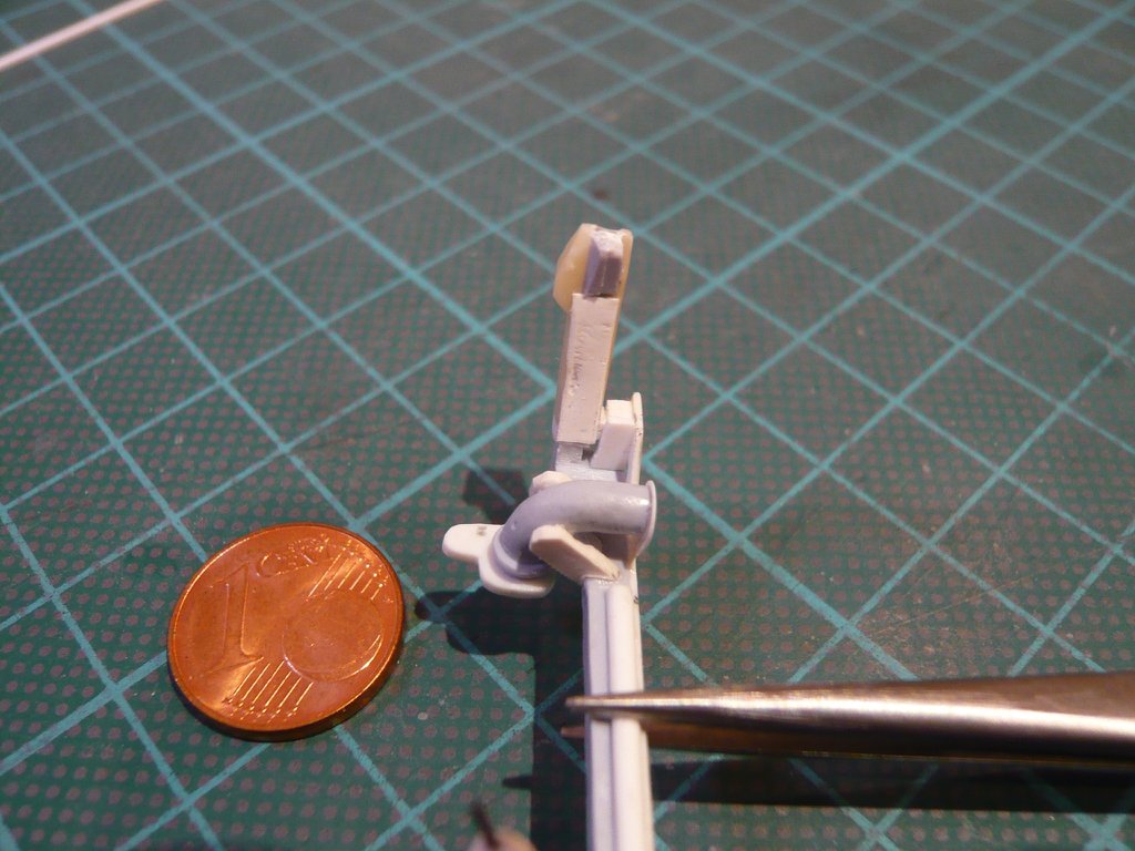
After I had punched it with the
Chisel cutter out of an
ABS Plate (1 mm) and smoothed the edges, it was glued at this point, directly in the corner between the
Distribution box and the
Cable Tray,
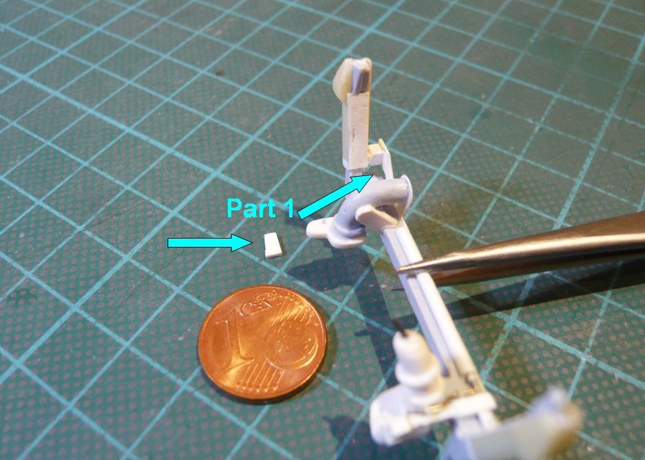
as one can see in these two images.
Then it went on with the
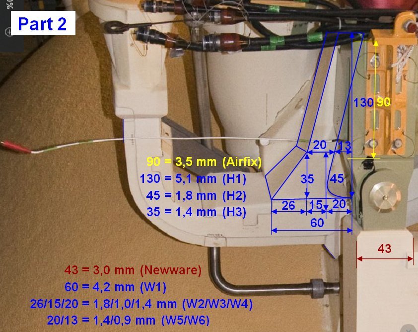
Part 2, whose shape one can only partially see in the photos, which has made the determination of the dimensions more difficult. Therefore, here again for a better distinction the color-coded
Parts (1-6) with their partially hidden contours.

 Source: forum.nasaspaceflight.com (DaveS)
In the next photo, it looks like
Part 2 is directly adjacent to the green end part of the
Crossbeam (Ball interface fitting), what I first assumed, but which is not the case.

On the other side, it is directly adjacent to the
LO2 Feedline Bracket, what one can clearly see in the zoom.
 Source: NASA
And from this image I have determined some dimensions of the parts, whereby in my experience for the determination of
Heights one should also use a
Reference height, and for
Widths accordingly a
Reference width too.

Since this is still not enough to be able to scratch the parts, I've analyzed this already several times shown photo (rotated) for the remaining dimensions, which is very well suited because of its high zoom resolution.

 Source: forum.nasaspaceflight.com (DaveS)
However, this image is very confusing due to the many dimensions, which is why
Part 2 can be seen here again separately.
Strictly speaking, the bottom of the part is not flat, but has down this triangular extension, but which I have not marked here and will suppress, since with about
0,4 mm it should be almost "invisible" and can be safely neglected ...

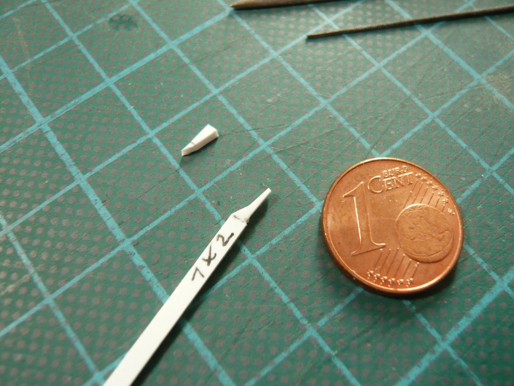
With these dimensions, I've then tried to scratch the part, whereby I first wanted to place it in an
Evergreen strip (1 mm x 2 mm),

but which seemed a bit too puny to me.

Therefore, I will start another trial with an
ABS Plate (1 mm) too.
Previously I had drilled the opening for the
GO2 Press. Line (Ø 0,4 mm) into the
Umbilical Plate and threaded the
Nickel Silver Rod on a trial basis.
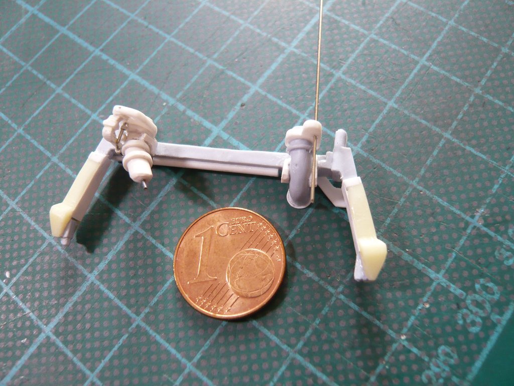
That should be enough for today.

