Hi everybody,
so then to bending and installation of the end piece of the
GO2 Press. Line.
First of all, it is necessary to know the preliminary end point of this gas line in order to be able to start bending, but this time it is relatively easy, since behind the last
Ice Frost Ramp from the
Newware Kit (R25) there are only two bends in the pipe.
 Source: forum.nasaspaceflight.com (Jester)
That's why I've used again my often shown ingenious
Reference drawing from the recommendable
ET Bible (System Definition Handbook SLWT - Lockheed Martin), from which one can take the exact location of the
GO2 Press. Line (light blue) and of the
GH[sub]2[/sub] Press. Line (red) direct next to the
LO2 Feedline (dark blue).
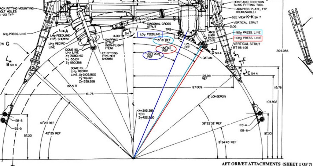 Source: System Definition Handbook SLWT, Vol. II (Lockheed Martin)
And these three angles I've drawn into a
1:144 drawing of the ET cross section, and layed one of the 14 following
Ramps (R23), in which both
Press. Lines run up to the
Intertank.
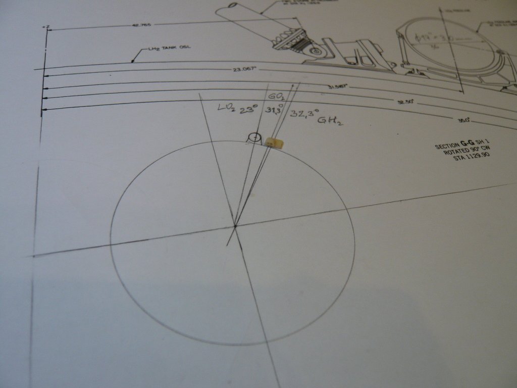
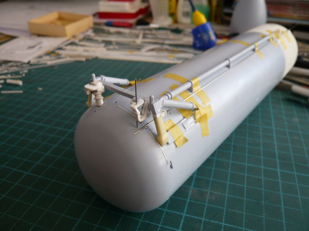
In this image, in front of it lays the last
Ramp (R25), whose position next to the feedline is crucial for bending the
GO2 Press. Line.
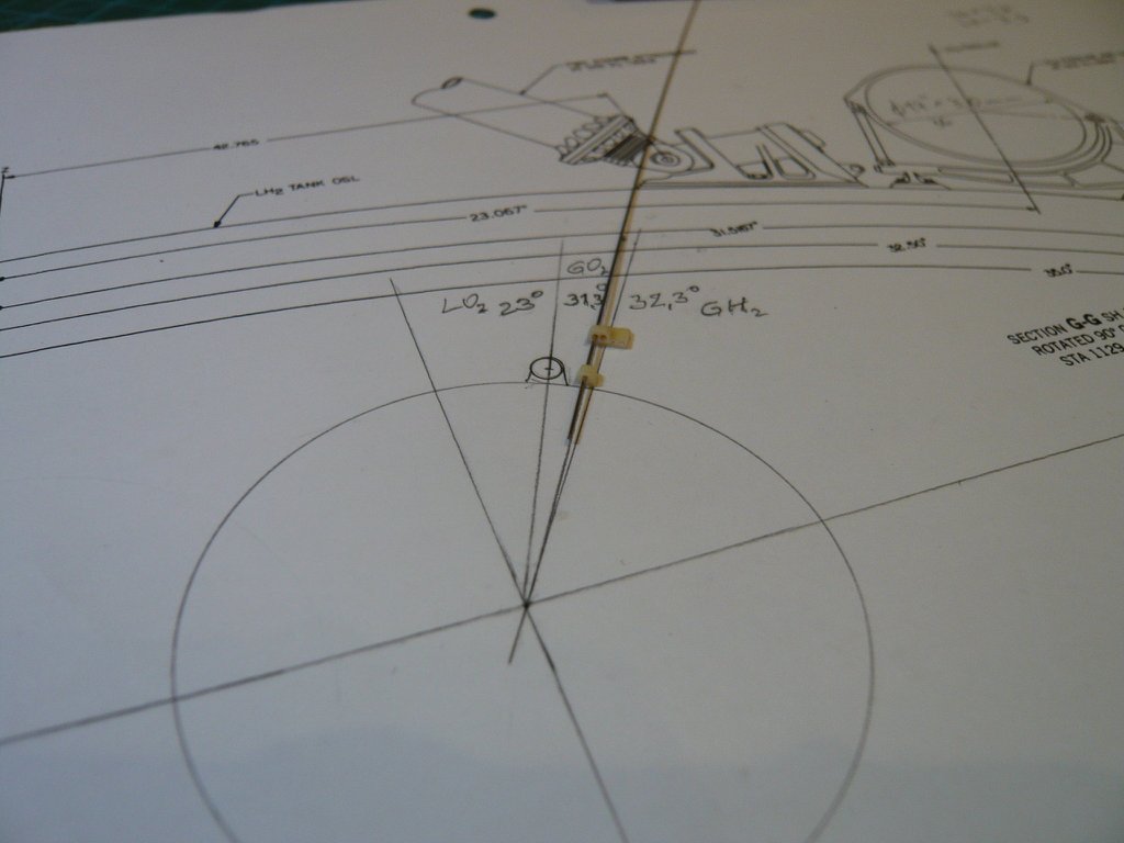
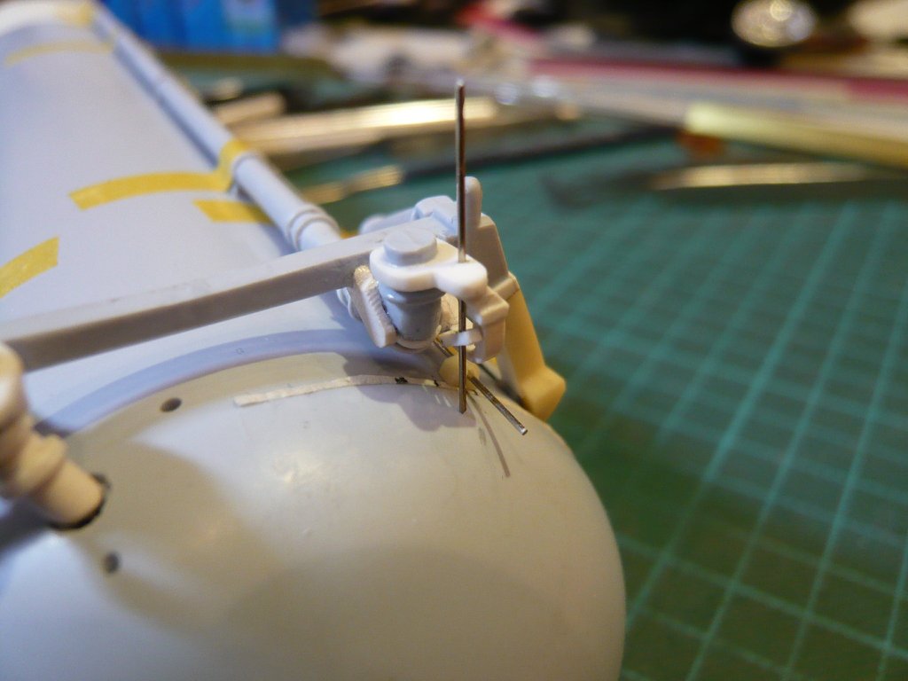
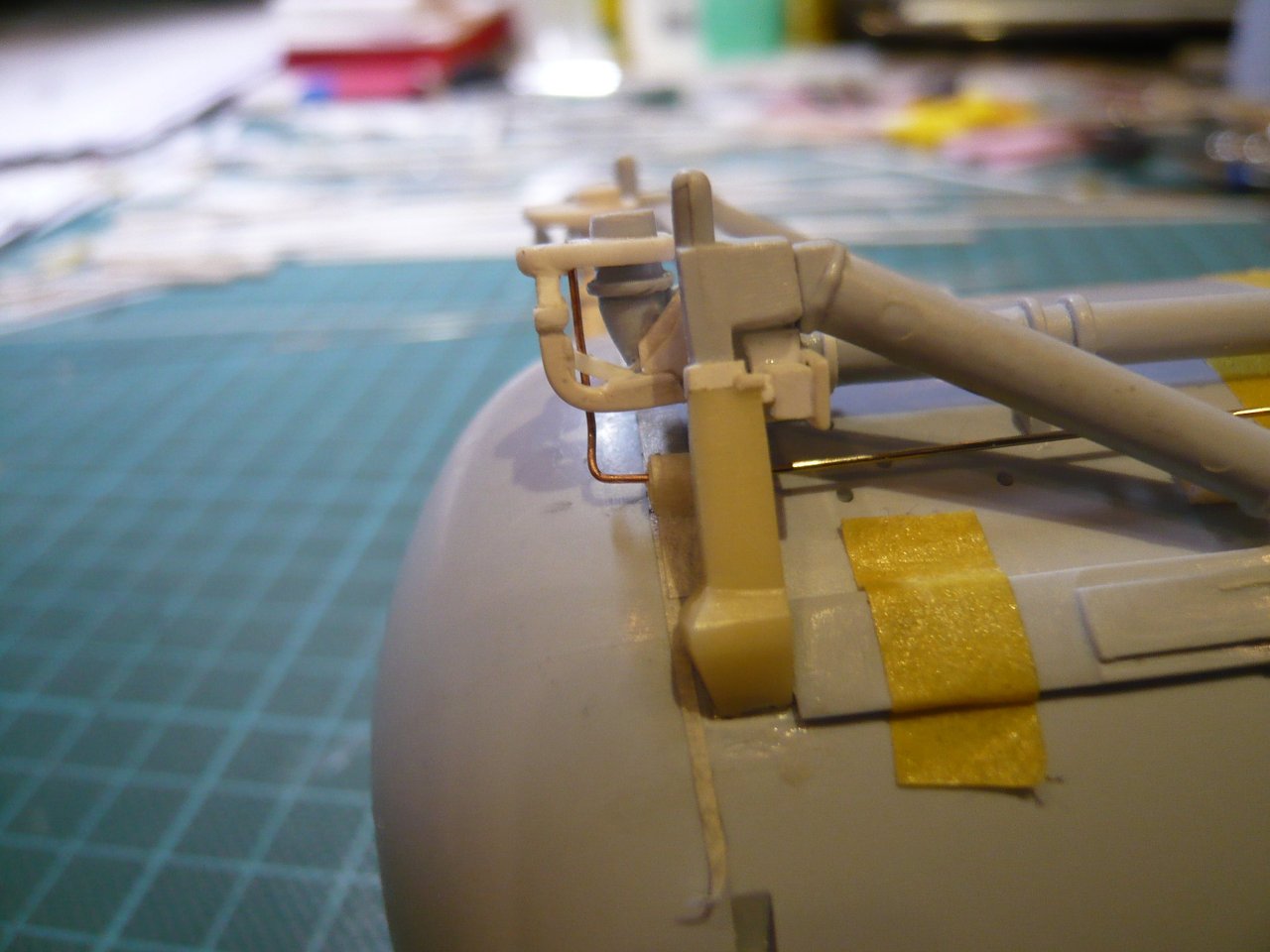
In order to determine their position as accurately as possible and to be able to transfer to the ET circumference, I have marked corresponding markings for all three lines on a
Masking tape (1 mm).
This tape I've glued onto the ET and then threaded a short piece of the Press. Line
(Nickel silver Ø 0,4 mm) through the
Umbilical plate and the
Bracket , as well as provisionally layed a longer piece of the line onto the tank.
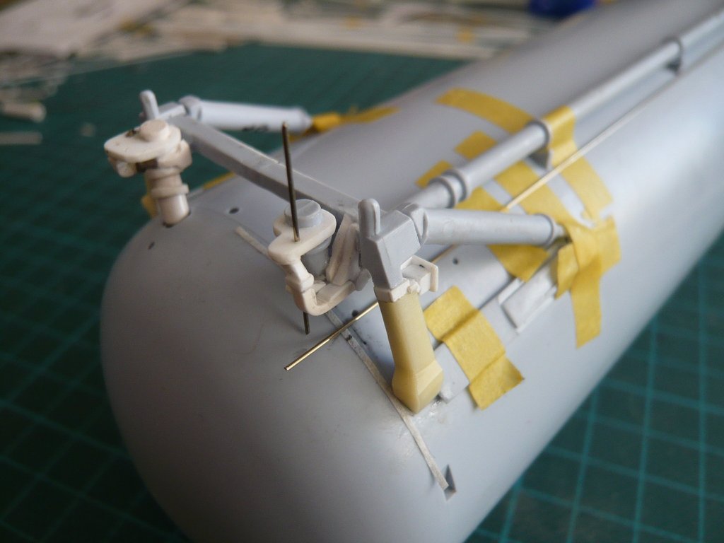
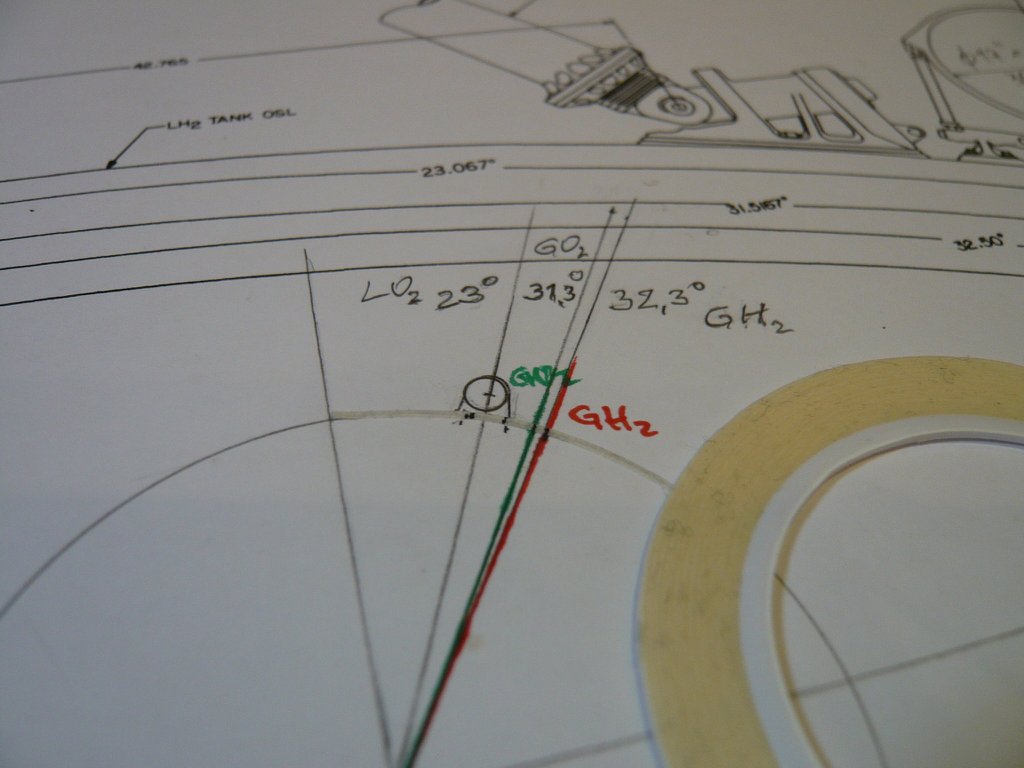
In order to be able to determine the distances of the lines from each other as well as from the last ramp as exactly as possible, I have threaded the
Ramp R25, as well as four
Ramps R23 to the front, and have fixed the line in this position with tape.
Afterwards the distance of both lines is
approx. 2 mm, which agrees well with the distance determined from photos,
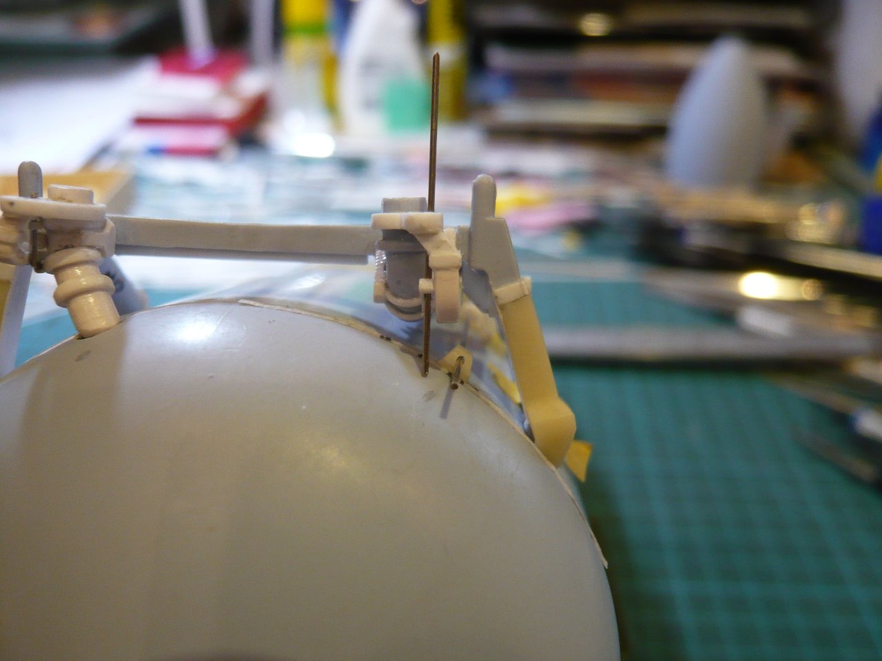
with which I could actually bend the short piece of the line.

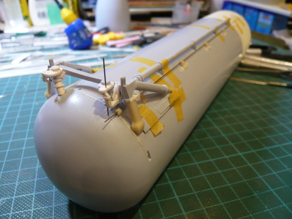
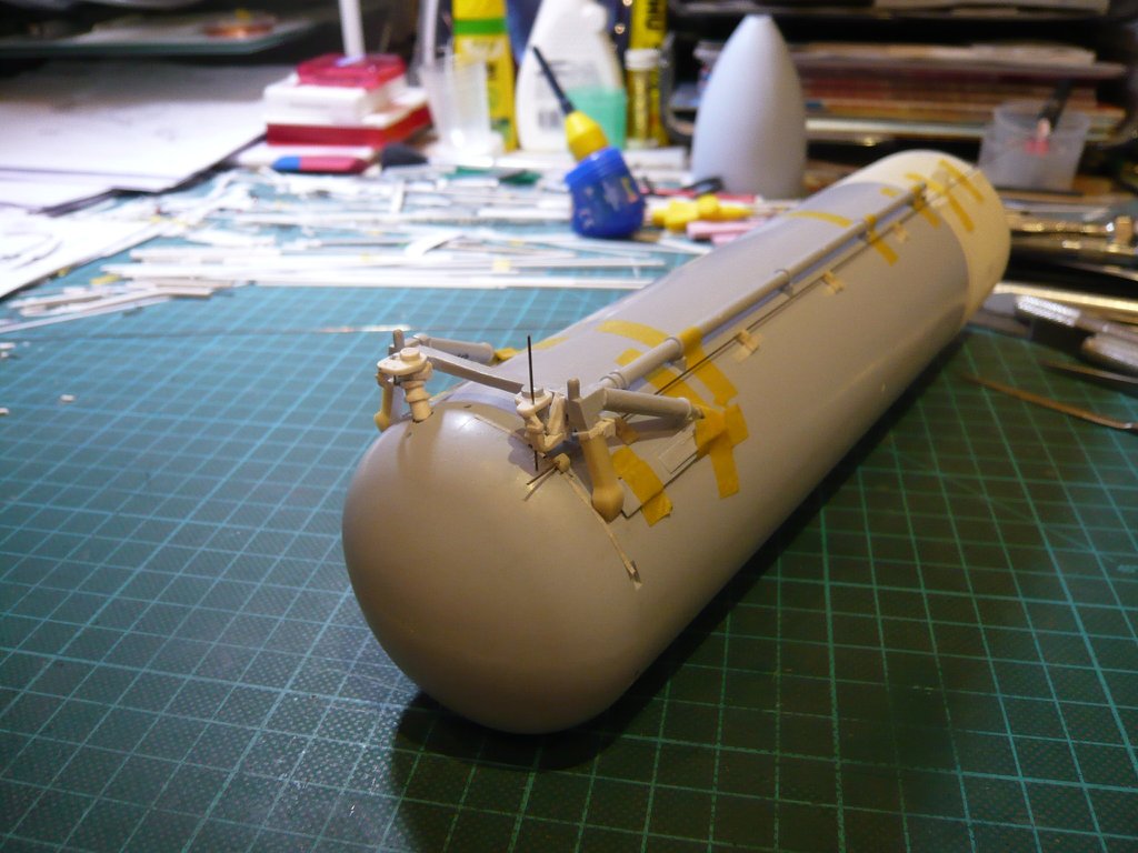
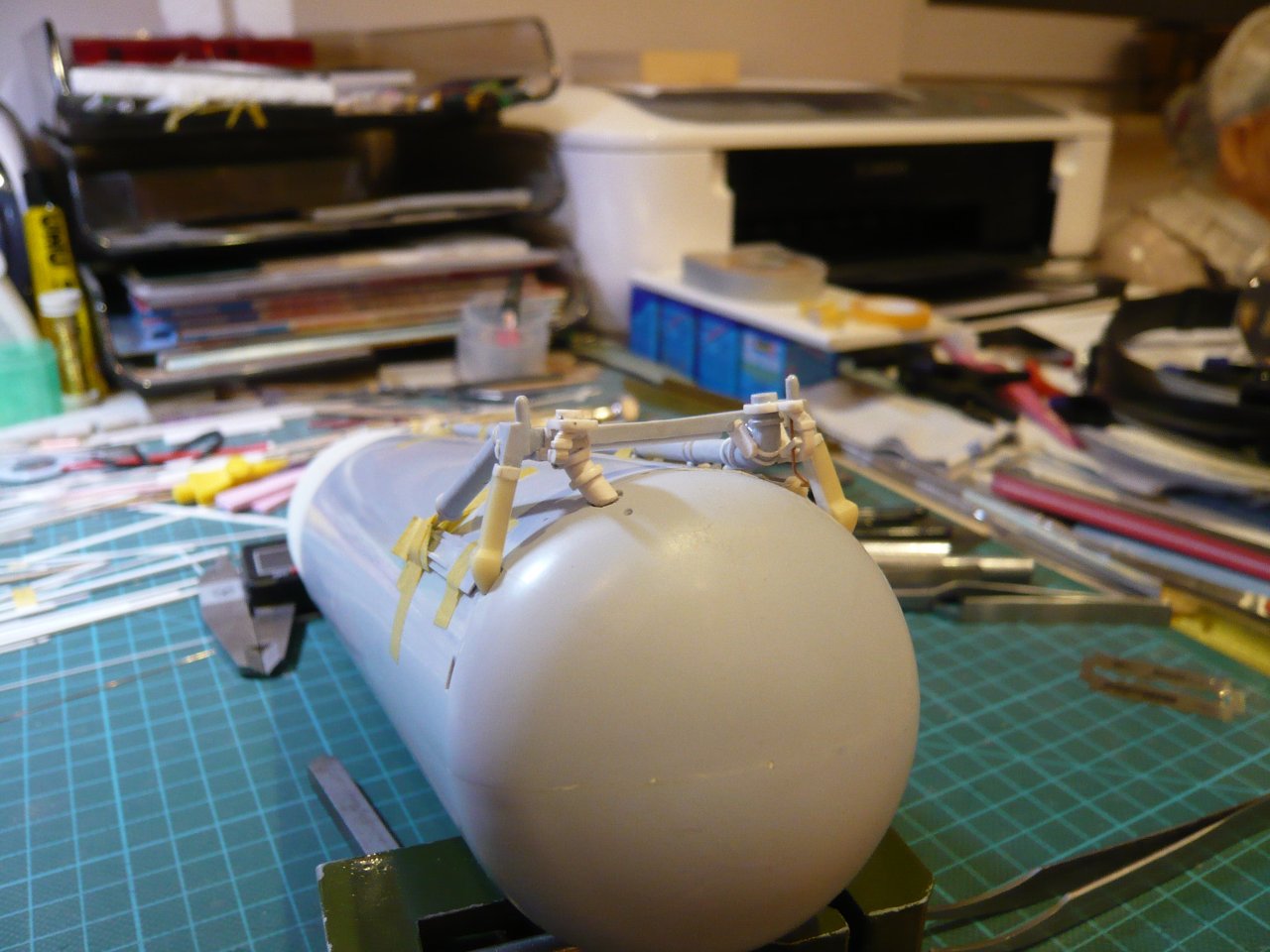
But to relax the eyes stressed out by the macro shots

is here a look from the normal viewer's perspective.
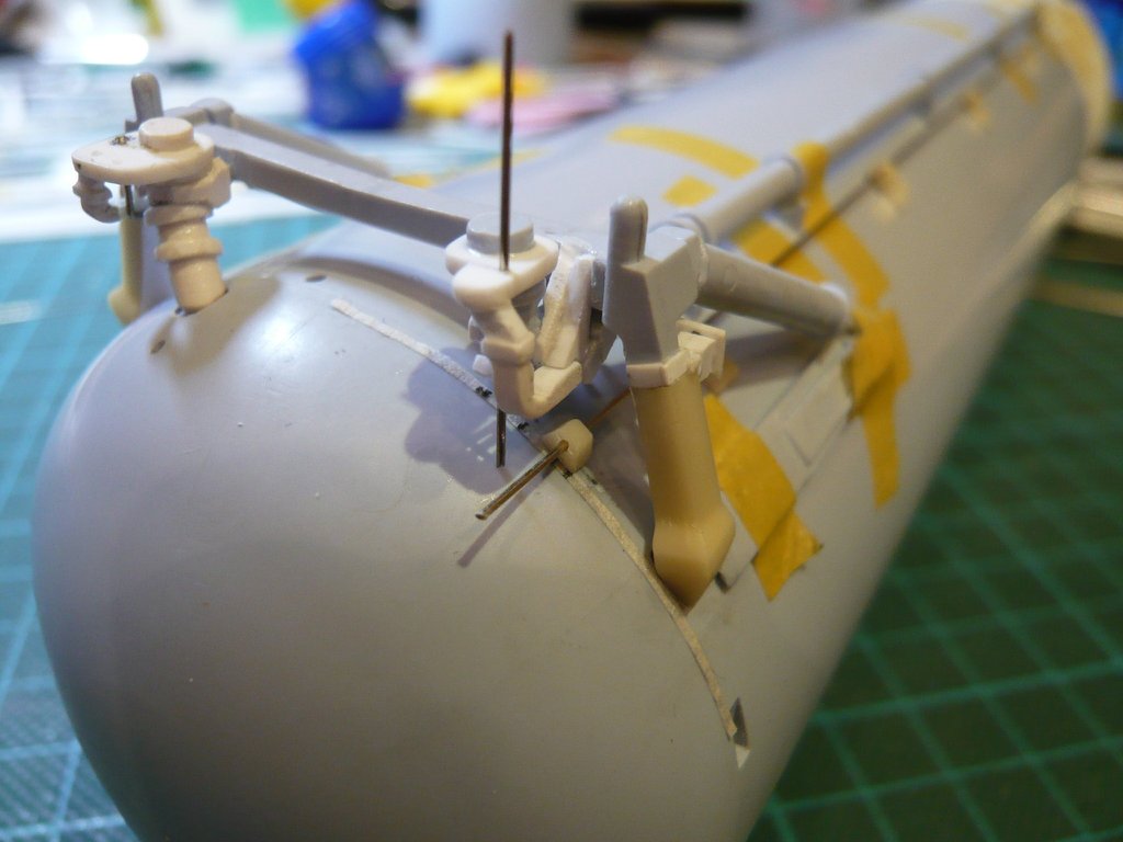
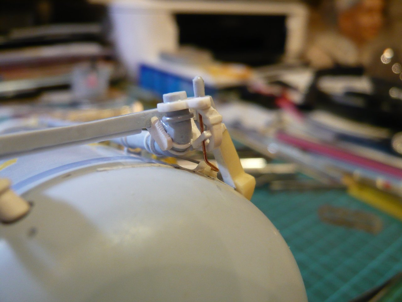
And since I was curious, I immediately made a first test-bending with a
Copper dummy (Ø 0,4 mm), and as one can see here, the result looks already quite useful.

Similarly, I'll now next bend the same line piece of
Nickel silver (Ø 0,4 mm) and then also attach the three
Fittings made of insulating tube, wherewith then the
LO2 Umbilical would have been finished.

