|

03-28-2020, 02:06 AM
|
 |
Member
|
|
Join Date: Apr 2012
Location: Filderstadt, Germany
Posts: 2,197
Total Downloaded: 5.57 MB
|
|
Hello everybody,
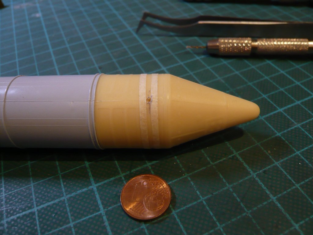
in order to be able to mark the point for the bore a little more precisely, I've dabbed the support rod with marker ink and carefully lowered the booster. When contacting it should leave a small dot of ink precisely where the hole is to be drilled. 
But it is almost impossible to hit the exact point for the bore, because one cannot align the SRB skirt so precisely by hand onto the Intertank. But this is not necessary either because it is sufficient to mark a short contact line with the rod's ink circumferentially on the Intertank, because the exact point for the bore results at the intersection of this line with the longitudinal engraving on the skirt. 
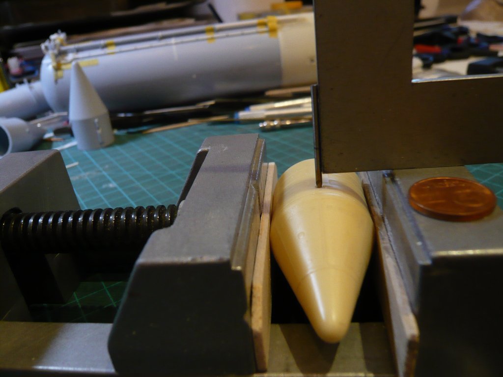
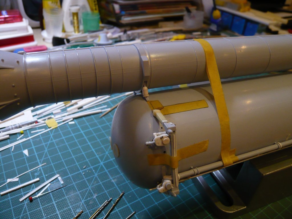
That's why I applied this method also still at the right SRB skirt with the tapes, the result of which can be seen here.
The more precise point is therefore a little bit further ahead. 
A nd therefore: Nothing ventured, nothing gained! - Let's get on with it!
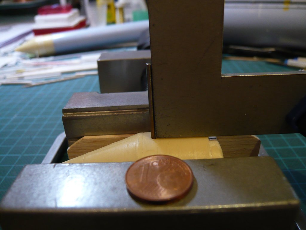
Before with drilling it could really come down to business, the vice onto the drill stand was carefully aligned so that the drill came to stand directly over the pre-drilled hole, whereupon this arrangement was then firmly fixed to the table top with a screw clamp.
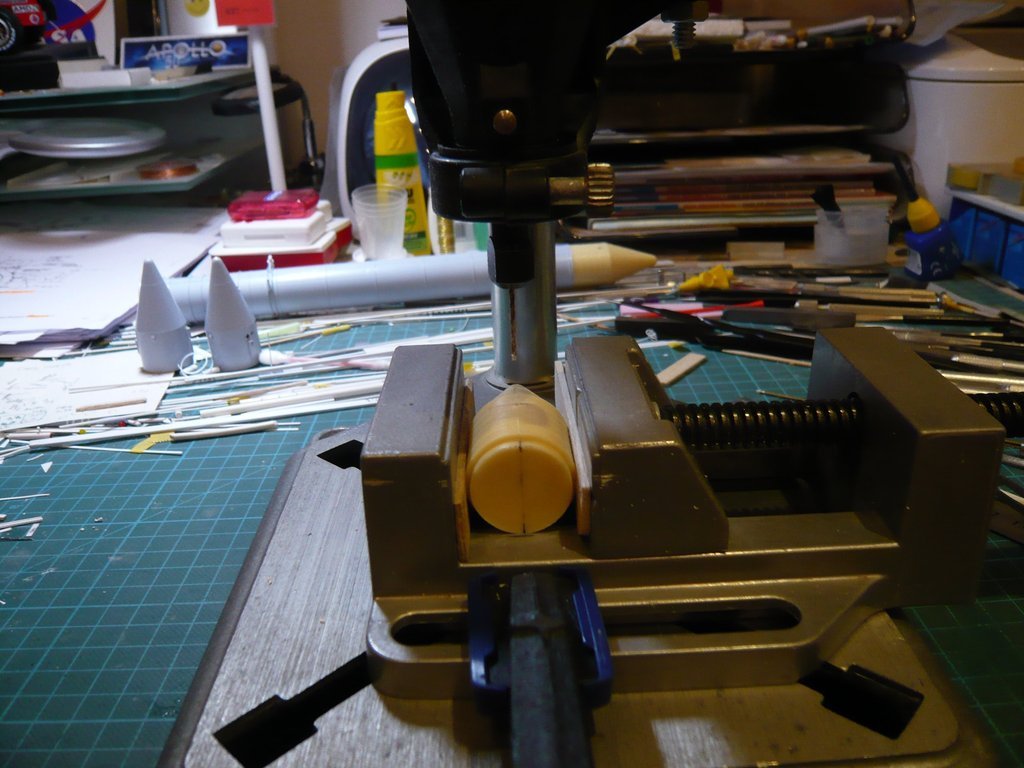
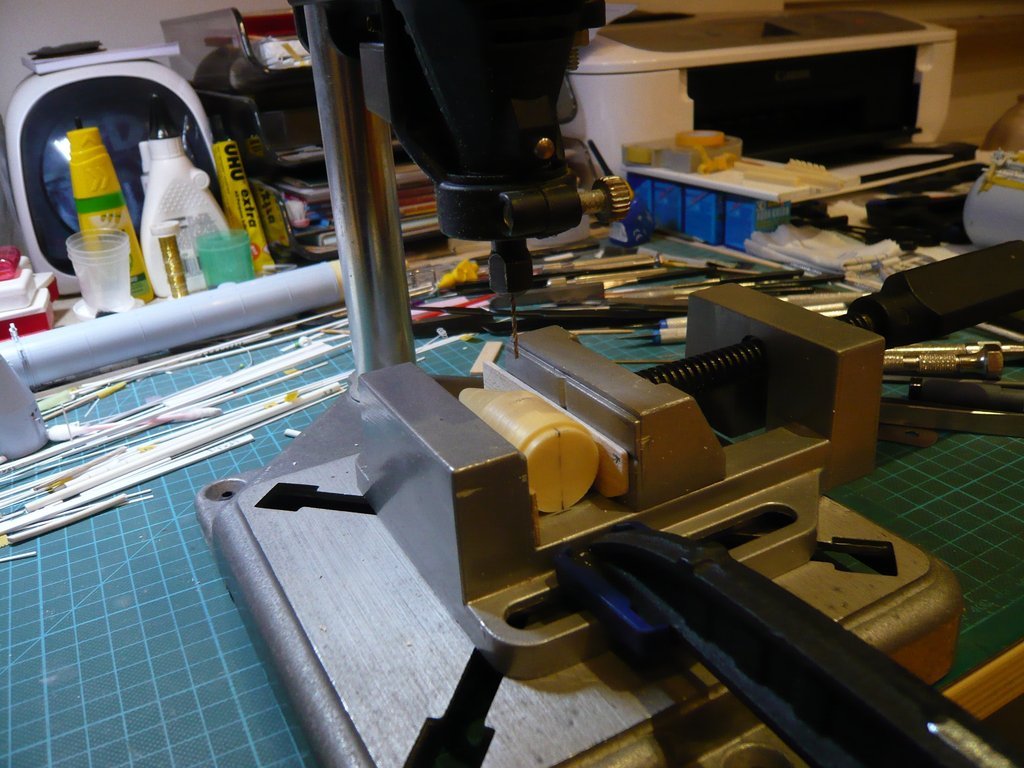
Then, as with the test bores, the holes were drilled step by step, first carefully pre-drilled with Ø 1,3 mm, after which this bore was then drilled out with Ø 1,4 mm and Ø 1,5 mm to a depth approx. of 20 mm.
And as the following two images show, the orthogonality was surprisingly good in both directions.
Then the front part was inserted into the booster and with the bore put onto the Support rod in the Intertank, as well as put down with the two rear struts above the openings at the ET's rear,
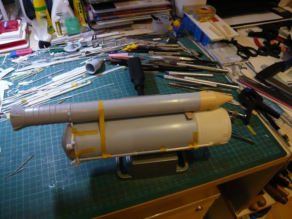
whose feet had to slightly ground until they fit in the openings. 
At the front end a Balsa board (2 mm) was inserted as a spacer,
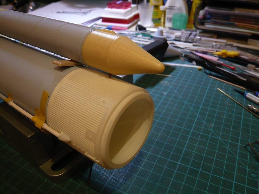
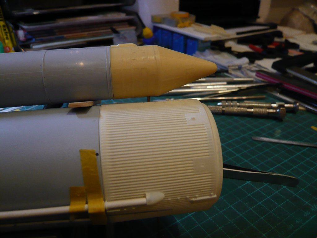
since the already mentioned SRB Thrust Fitting has to be glued directly behind the support bar, which is unfortunately missing at the Newware front parts, 
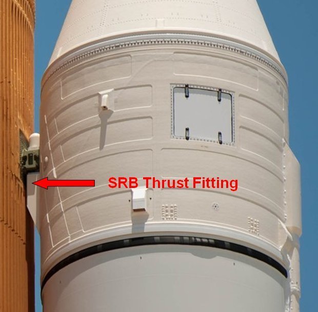
Source: NASA
which is why I have to scratch this part. 

|