Hello friends,
now that my new PC is running, it can finally continue on the
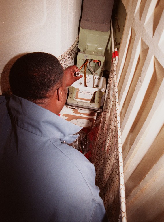
Stack-construction site,

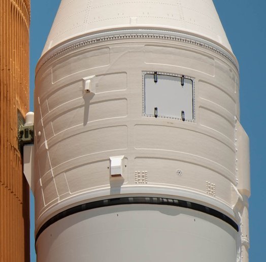
whereby it specifically concerns the front connection points between the
ET and the
SRBs, these are the so-called
ET/SRB Forward Attach Fittings, one of which was already shown in this picture, whereby the cladding over this green segment is missing.

 Source: NASA
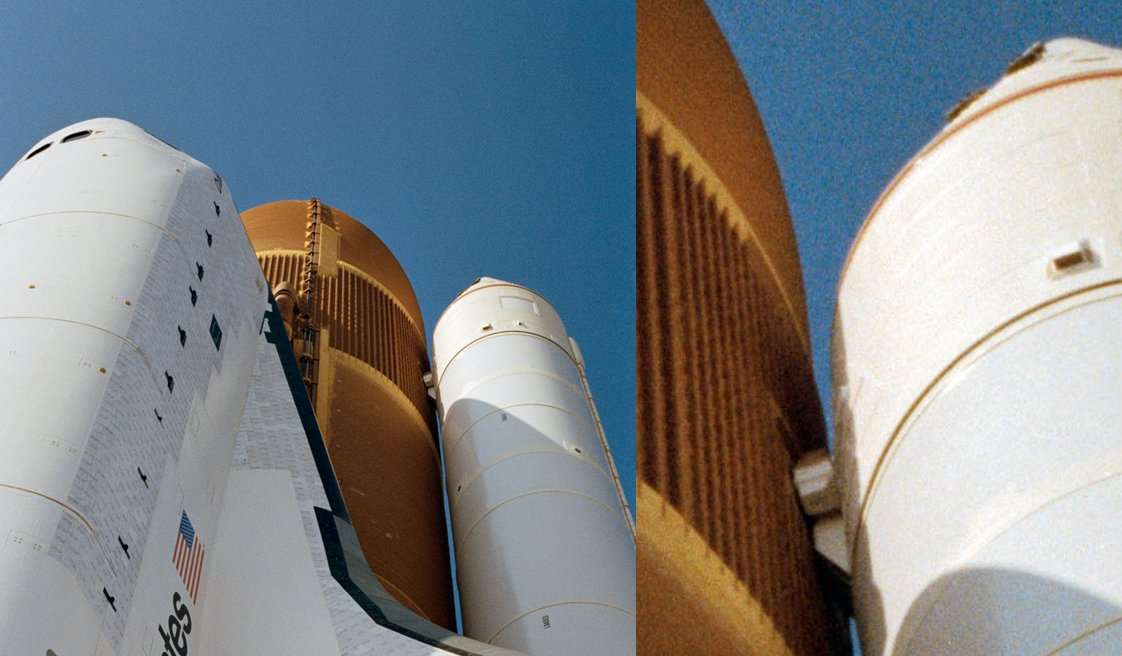
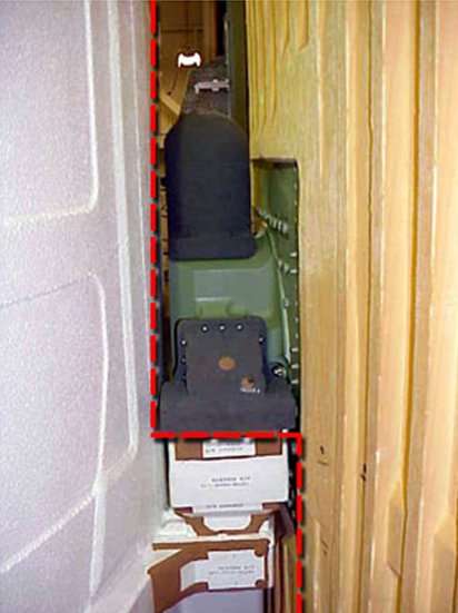
Apparently, this is not just a cladding, because as one can see in this photo of the
STS-6 Stack in the final state before the launch of the
Challenger, there are two white boxes stacked over one another. Since this image shows the front of the stack facing the orbiter, the question immediately arises as to how this connection assembly may have looked on the back.

 Source: forum.nasaspaceflight.com (woods170)
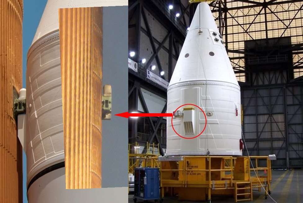
To find out, I had to do a bit more research and have found this photo of the
ET-121 after its separation from the
Discovery (STS-114), that was the so-called
Return To Flight Mission after the
Columbia disaster (STS-107).
On that one can see on the underside, although a little small, the part of the fitting that belongs to the
ET. The rest of the part is therefore on the previously blown away
Booster.
 Source: NASA
The following photo montage shows how the two assemblies of the attachment fit together.
Helpful for my understanding were these drawings of the
Attach Fitting, on which the parts belonging to the
ET are colored green and those of the
SRB are blue, which are connected by the
Separation Bolt.
 Source: System Definition Handbook SLWT, Vol. I (Lockheed Martin)
Final clarity about the arrangement of the fitting on the front I then got through these two photos,

here in opened state without cladding (
RSS Fairing)
 Source: NASA
and here with the gray cladding,
 Source: spaceflight.nasa.gov
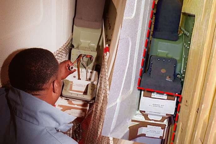
which I then compared directly in this photo montage.

Unfortunately, I did not have these photos available during the failure of my PC, which is why I've initially only orientated myself by the first photo at the beginning of the post that I had on my smartphone, but what unfortunately has led into the wrong direction when I began scratching the arrangement,

but what I still want to present to you.
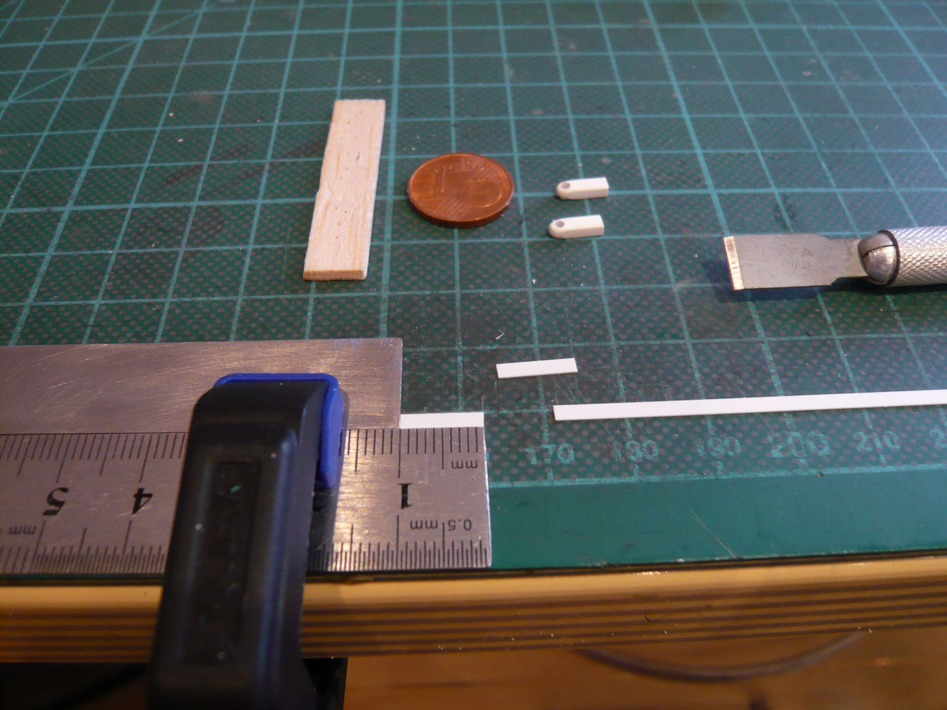
When scratching this fitting, I had to consider the support rod for the SRBs and drill a respective boring.
For the two-part basic body of the fitting I've used a
Rectangular profile (2 mm x 2,5 mm), which I rounded off at the front end to simulate the
Bolt Catcher and drilled out for the holding rod with Ø 1,5 mm, as one can see in this image.
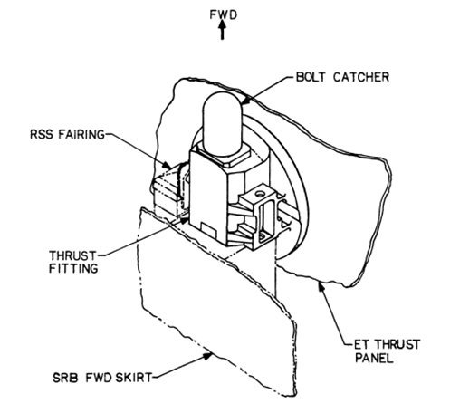
On this image one can see the assembly of a
Bolt Catcher, which catches the front part of the bolt that was blasted off when the booster was separated,
 Source: NASA
whose honeycomb-like inner structure can be seen here in detail.

 Source: NASA