Hello everybody,
now that the different lamp shapes on the Pad have been clarified and I know how to scratch them, I wanted more clarity about the wiring of the many
LED lamp circles with the power supply of my planned
Diorama (1/160, 160 cm x 90 cm).

And my diorama could look something like this
Mini-Diorama (1/700) by
Tomytec, whose base plate is only
35 cm x 29 cm "big", but had a moon price of
682,30 €, but has been sold out since then.

 Source: Andromeda24.de
At first I had only planned a fixed arrangement/wiring of all pad structures/components in the starting position for the Dio, i.e. with the
MLP with the
Shuttle stack on the
6 Pedestals next to the tower, as well as with the
Crawler on its way before it.
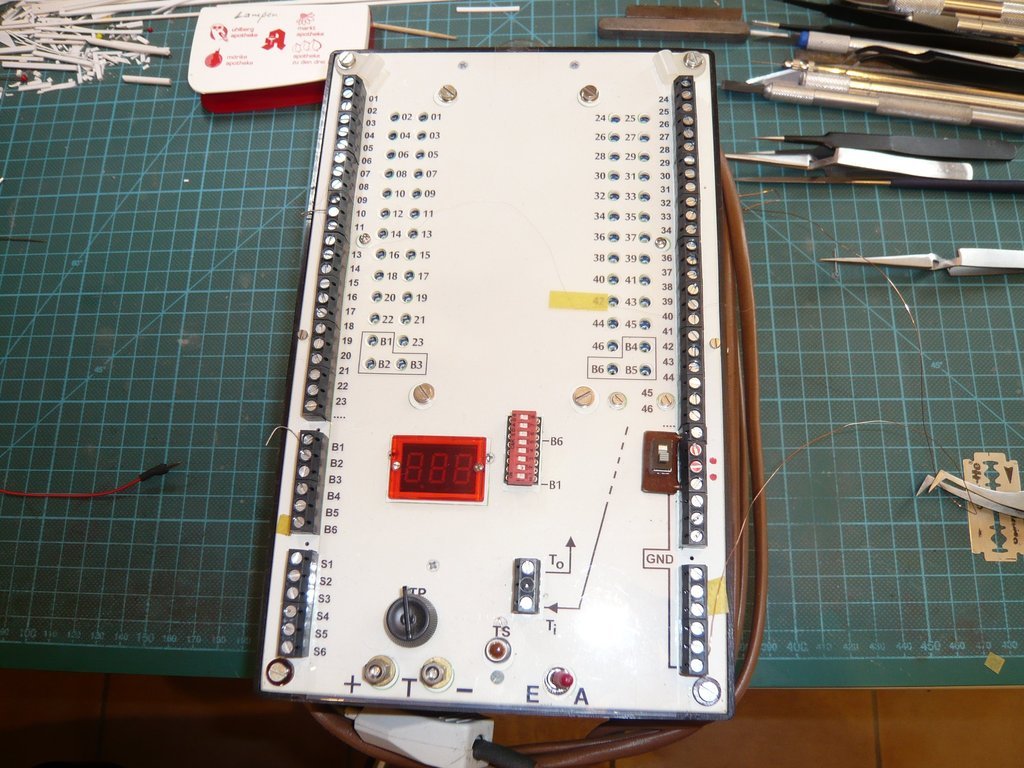
The concept for the power supply for lighting the entire diorama was developed a few years ago in a close exchange with my Raumcon friend Arno (
McPhönix), in which the
Multi-Currentbank is the central component, which is designed for
approx. 60 constant current circuits each with up to
8 LEDs, with which all lamp circuits of the
Launch pad (FSS/RSS/Service facilities/spotlights) as well as the [color=blue ]MLP[/color] and the
Crawler are powered.

This original concept has in the meantime been revised and modified with regard to more
location flexibility or
Mobility of MLP and Crawler so that not only this one arrangement is possible with the MLP standing in front of the tower, but also during the MLP approach to the pad, like in this photo during the
Challenger rollout (December 8th, 1982) in the fog.
 Source: forum.nasaspaceflight.com
Likewise the cabling between the diorama and the power bank has also been modified so that it can be separated if necessary.

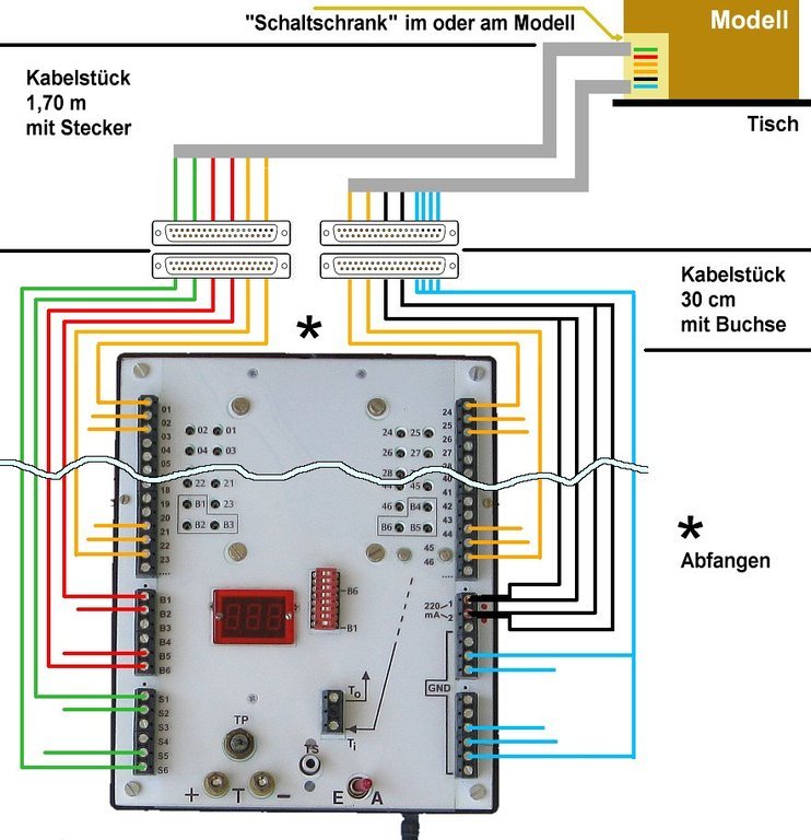
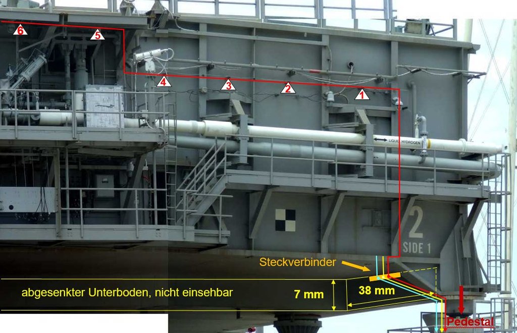
In this context, I initially had a detachable cable connection on the
MLP via a small
plug-in connector on the underbody next to the
Pedestal 3, which I have now moved to the other side and planned for the
Pedestal 6 besides the tower, since the whole cabling of the
FSS/RSS is also planned on this side and all cables/wires can be led down together to the pad bottom.

In order to be able to implement this mobile location concept, we have meanwhile also agreed to install our own power supply (three 9 V batteries) in the
Crawler, on what also the
MLP can be connected by means of a plug connection if it is in a pulled-out position on it.
Consequently, a suitable location had to be found for an interface between the power bank and the pad cabling, which is shown in this drawing with the
connection plate,
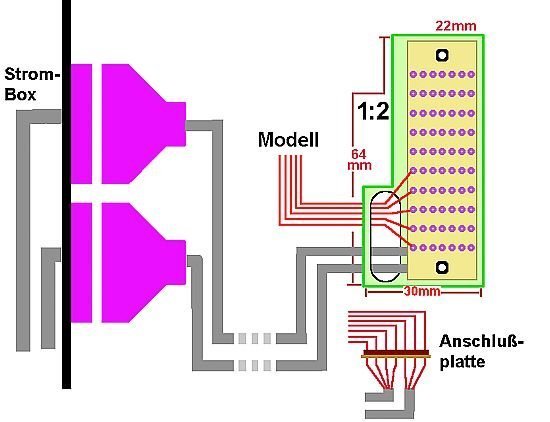 Source: McPhönix
whereby
NASA befriended us with the construction of the pad infrastructure with a small building, as will be shown later.

In order to get a better overview of the local conditions on the
Diorama as well as an idea of the size of the space available for the wiring of the pad assemblies, I picked out my former Dio draft, what for I've used an older one
Google Maps image (2012) on which was seen the
Launch Pad 39A in its original form with
FSS/RSS,
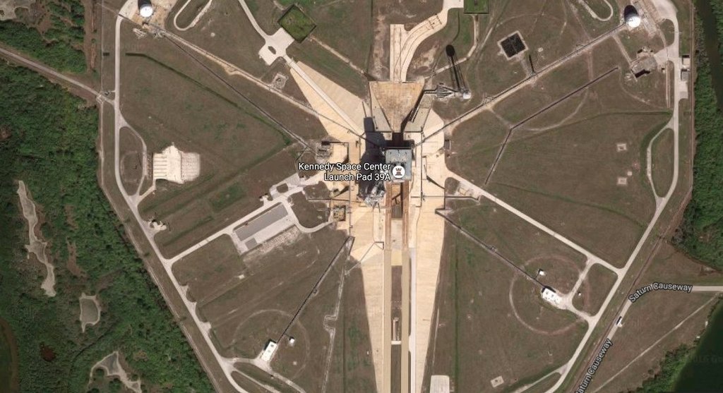
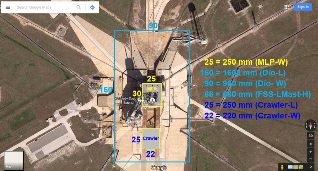
in which I have drawn the floor plan for the diorama in the
Scale 1:160 (1600 mm x 900 mm) and marked the MLP and the crawler.
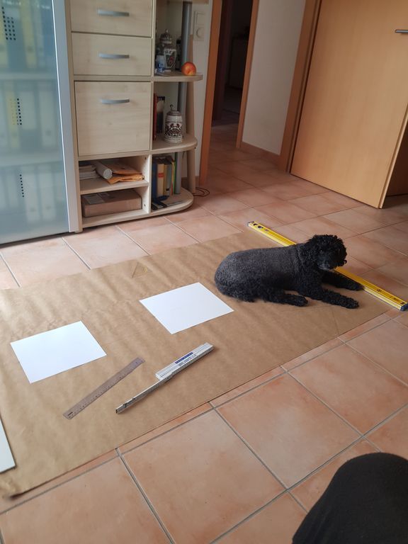
Then I've drawn the Dio to scale on paper and put on placeholders for the MLP and the crawler, for which I had to roll up the carpet in the study. And while I kept checking the dimensions on the PC in between,
Gino had made himself comfortable at the end of the
Flame Trench and began falling asleep ...

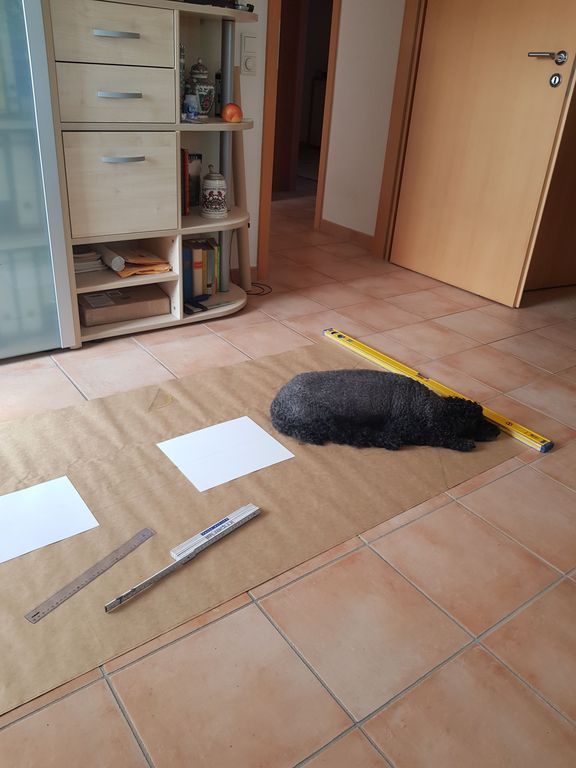
And since it was already late or early again, we've went to sleep together ...

And with that, good night ...
