


|
|
|
#1
 04-11-2014, 05:43 AM
|
|||
|
|||
|
Modelik BTR-80
Decided to try the modelik BTR-80.
Modelik page 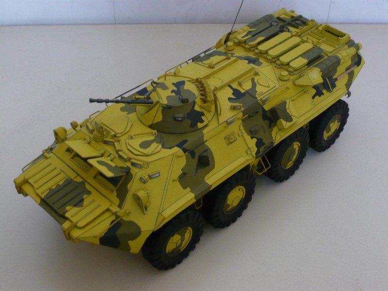 Unfortunately after beginning my inner framework I found some threads which report a lot of issues.  I decided to continue as is & see how far I could get, because 1. I know it won't be all my fault  & 2. I might learn something different about how to really make a model. TBH I don't know if I will finish it but I am gonna push into it anyways. & 2. I might learn something different about how to really make a model. TBH I don't know if I will finish it but I am gonna push into it anyways.These threads are by Eastern European Masters who knew how to make the the necessary alterations on the fly. The most immediate problem was the difference in skin to card inner frame. This affects the upper skin & the wheel wells/suspension mounting areas. But other little errors exist like no rear lights in the kit! http://www.konradus.com/  - This guy was able to make a new suspension setup as well as overcoming the errors. http://www.kartonwork.pl 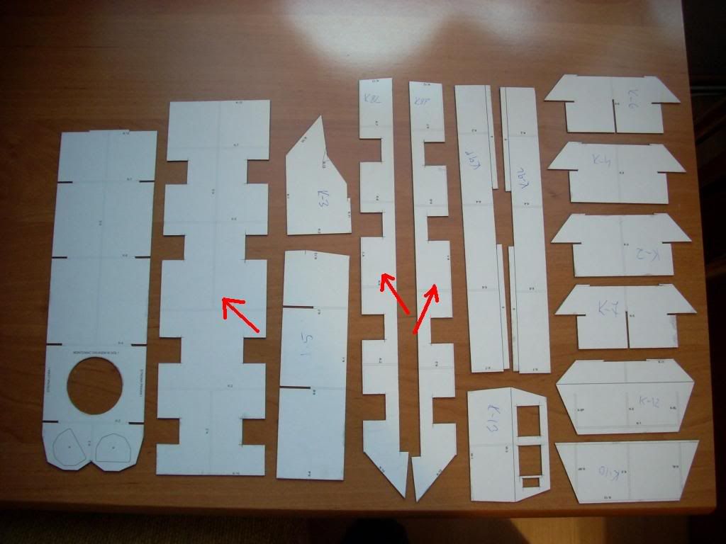 - Repaint & custom wheels construction http://papirovemodelarstvi.cz 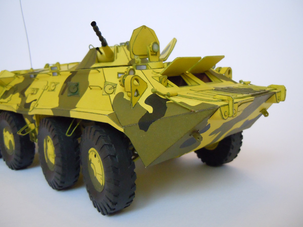 - guessing this is the builder of the one shown on Modeliks site. http://www.cardarmy.ru/ 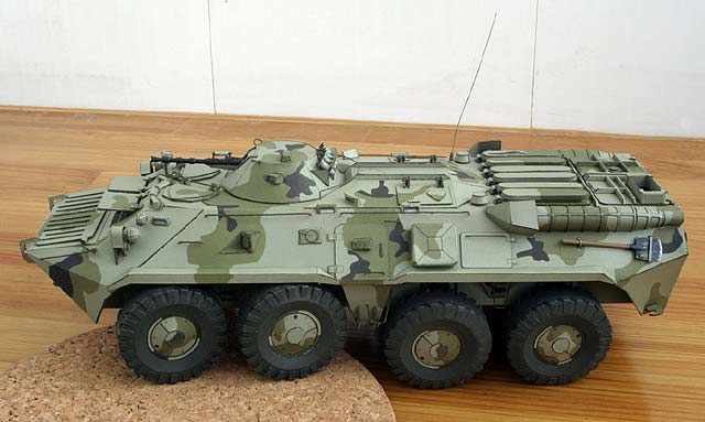 - a great repaint with working suspension. Lot of errors mentioned. This thread will be an attempt to trace some of my findings as a non-pro (& in English!!!) so others can attempt the beast with the benefit of expert builds reference & my experience all in one spot. To make things awkward I don't have a camera to hand so until I do I will be using other means & link the pics on the above threads to give some ideas about what is going on. 
|
| Google Adsense |
|
#2
04-11-2014, 06:08 AM
|
||||
|
||||
|
Sounds like it'll be a very challenging project. Good luck.
__________________
Regards, Don I don't always build models, but when I do... I prefer paper. Keep your scissors sharp, my friends.
|
|
#3
04-11-2014, 06:57 AM
|
|||
|
|||
|
Thanks rockpaperscissor, I will certainly be needing something to get thru this
--- I found that inner frame to be off exactly as described. ") As I said I'm just going to see how it goes. One builder reworked the top skin, this meant that the front/nose skin had to be modified too. Not for me...! The gap between the top skin & the frame I've decided to fill with some extra card stock for support. re www.kartonwork.pl 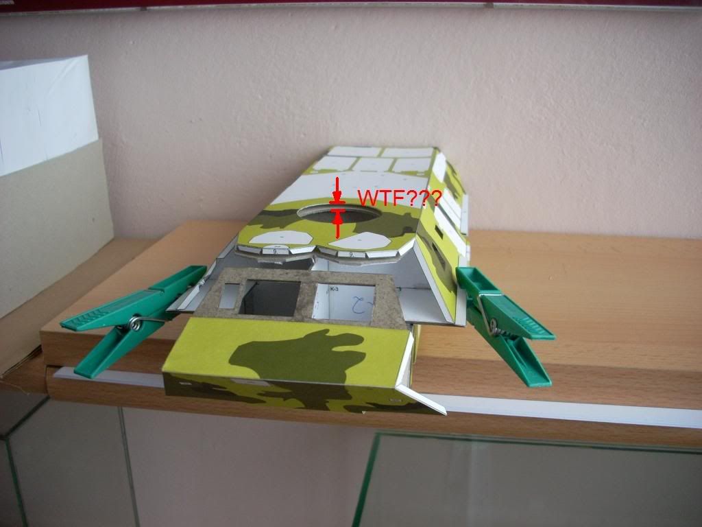 (I'm adding the instructions pages & the part numbers so people with the model can follow along.) The wheel/suspension wells - I didn't cut/pad the frame to match the bottom skin. This leaves a few mm unsupported & proud at the sides of each bay but I'm hoping the presence of suspension & wheels will mask this. (green circles) Reworking the frame, at K8 & K1 + well enclosures, to match bottom skin [part 4] wasn't an option for me as I'd cut & glued it all before I found the threads on the errors. Should have double checked with the bottom skin but the 1mm shift got past me. The solution - re www.kartonwork.pl 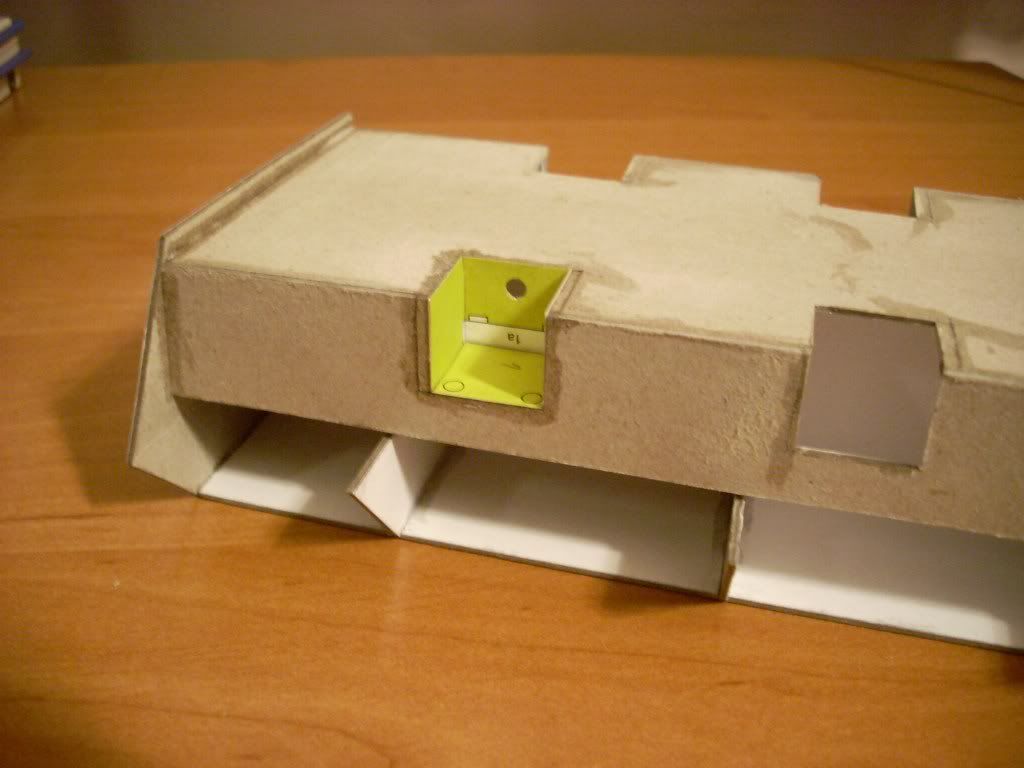 I fitted the top skin [8] with a bit of extra bulking up on top, the upside is it does match the nose skin & connects Ok with a nudge here & there. Finding the nose frame REALLY tight to the nose skin, I shaved down the edges of the frame [part k10] & then wrapped it round. I'd shaped the nose [parts 9, 7, 12] before trying to attach it because I figured without assembling that first 'correctly' I had no chance of checking frame issues. Turned out to be a good move because of the tightness on dimensions between skin & frame at the front. I then needed to glue the nose skin to one side, let it dry completely & then s-t-r-e-t-c-h it over & glue the other edge. I started on the left (looking at it nose on) so I could fit the firing port [part 24] properly. (Red circles)
|
|
#4
04-11-2014, 07:17 AM
|
|||
|
|||
|
The shock absorbers have locating circles printed on the well boxes. [1, 2, 3]
These alternate 2 shocks / 1 shock for each pair of wheels. (see instructions below) 'kierowane' being the front steering pair. Another clue for this is that the suspension yokes have a black circle as a mounting point on them. The shocks [59s, 59t] themselves have an outer tube & an inner rolled 'bar'. The problem is there is no indication in the sparse instructions of how much bar should be in the sleeve to allow correct orientation of the yokes & thus prevent the wheels fouling the body. I have decided to roll some more bars to drop inside the sleeves & obtain a fixed extension distance. Still working on how long these will be - quite tricky without actually assembling it all, lol.
|
|
#6
04-18-2014, 12:37 PM
|
|||
|
|||
|
Thanks Tim
I found some bowing & a slight mismatch where the door area & 'sill' fits the frame. The upper hull skin is one of the biggest parts [8] I didn't want to attempt to trim it & probably lose the shape of the upper hull/mess up locations for other elements. I instead trimmed the frame, widening the step to fit the door mounting area on [8]. This is only a few mm, & the chopped off bit can be added to the sill on [8] at other end of the gap if desired I found that cutting a 'Y' into both the door spaces has allowed enough flex into the upper hull to shape it properly as it was attached to the frame. The Y cut will be hidden by the door assembly. Back to the suspension. After some head scratching I decided to roll some more 'bar'. For the rear suspension - the sheath [59f] is approx 12mm deep, the insert is approx 13mm. Fully inserted, this is nowhere near enough to set the yokes at an acceptable angle to the horizontal as shown in the instructions. I made strips 5mm wide & 30mm long, rolled (not too tight) these are thin enough to make a stable plug but are still retrievable from the sheath if necessary. These are to be used to give a decent fixed boost to the position of the 6 rear inserts [59f']. I am planning to use 2-3mm plugs in the front 6 sheaths [59s] as this seems enough for the 4-5mm depth. I need to test the rear wheel positions to be certain, unfortunately I won't be able to see until at least 1 of each suspension assembly (steering & rear) is built to judge alignment. I think the best option would be to make your own struts as this would probably be stronger. The length (to be determined) would comprise the current insert + the blank plug I am using. Obviously I don't know why the designer didn't use this approach as he must have faced the question of suspension angles. A gauge/jig would have been useful. As it is, I will post the measurements I use as a start for anyone else looking at these assemblies, when I have a clue as to how it turns out.
|
|
#7
04-20-2014, 06:57 AM
|
|||
|
|||
|
Found a camera!
These images show some of my progress. 1) I decided to partially assemble the drive hub / yoke / piston, so I could pre-align a few elements. 2) The hub has a tab to attach it to the yoke but the edging strip needs a tooth cut into it to make the join by the tab tidy. 3) The body work assemblies don't quite match the (distorted) dimensions of the lower hull skin. I think this will be mostly concealed by the wheels however. The gap where the door assembly & frame mismatch is shown So far the adding of packing to the shock absorber tubes seems to be working & the assemblies do seem to be fairly even & actually don't look too bad at all. Will be doing some more pics, but this is an ancient Nikon that hasn't been used for a while ...
|
|
#8
04-24-2014, 07:07 AM
|
|||
|
|||
|
I should have mentioned the instructions state that the drive hubs (pear shapes) should be mounted on Bristol.
However I found that card was needed both to match the edging strips width & to give some depth for wheel / drive shaft mounting. The idea of adding fixed length blocks to the shock absorber base sleeves seems to have helped keep things in line. The result is stronger than expected & may yet work out OK. Started on the wheels. The design allows for the tread pattern to be cut out (like maestro Enrico63's wheels) but I decided that I'd just try & keep the tread facing in the right direction for now. Didn't think the wheel design was too bad, kinda low-intermediate skill level I guess. Also started the mufflers, have to say I kinda like the pesky petals - when I can get them to behave.
|
|
#9
05-21-2014, 05:17 AM
|
|||
|
|||
|
Discovered when fitting the window assemblies that the frame [k-13] seems slightly off & required surgery in situ. I'd suggest that builders make the windows & test fit them in the frame before assembling it, same obviously goes for the skin [9].
I noted that both experts placed the side mounted optics on the outside of the turret, the instruction diagram suggests it is recessed. Couldn't find any pics of a real one that clearly showed it either way, & I suspect there may be variants, so went along with the external placement. When looking for info on the smoke launchers I discovered this picture of a yellow/green BTR-80 which could be the designers inspiration. Optics aren't recessed. The picture was a big help with the 81mm mortar placement. The expert builders made their launchers stand off more from the turret than the picture shows. The turret skin has an arched guide line, which I take to mean that the rack is up close & fixed in a bowed upwards arrangement. This makes sense from a smoke deployment POV. This idea is supported by the photo of the real deal. Unfortunately the triangle brackets [58a] placed between the tubes are right angled. The curve of the turret & the arch of the rack makes these awkward to use. I modified them in the hopes of a more natural & flush mortar mount. I also decided to use some edging face strips. These I cut from the leftovers of the side gutters [18] The turret is probably not meant to have a hole for it's mounting in the top frame [k-11]. I think it is just pinned to the spot. I'd cut this hole out so I rigged a circular band on the base of the turret to allow it to sit in the hole firmly but with enough freedom to rotate. Despite the problems with designer/print (& builder!) I am quite pleased so far. It looks like it will be a cool model in spite of the snafu's. I would say it's definitely worth building if only for the education in paper problem solving.
|
 |
|
|


 Linear Mode

