


|
|
|
#1
 06-22-2008, 07:35 AM
|
||||
|
||||
|
1/72 Convair B-36 Peacemaker
Hi guys! I'm a newbie of this forum. I've been collecting diecast airplane models for several years though, I realized that I had to make a model what I want by myself, which means that almost of all those assembled models have some issues and they can't be beyond my allowance whichi is not too high. So, I got started making my origianal models. However, I don't have any cup and skill. It looks kinda audacity though, I wanna make it with your helps/tips/ informations and finish this model although I'm not sure how long it will take. I appreciate all the inputs from you all!!!
Here's one of my model, 1/72 B-36. To be honest, I wanted to make it in 1/32 scale though, I gave up as there's no room in my tiny house. I got started the cockpit section first. Major bulkheads of the cockpit section were drawn on a cardboard which had a thickness of 2mm. Though it looked kinda too thick, I thought this section needed sufficient stiffness since this section is to be a base portion of a nose gear and to be installed a weight to fix a tail strike issue (I believe this model is gonna be a tail heavy model.) 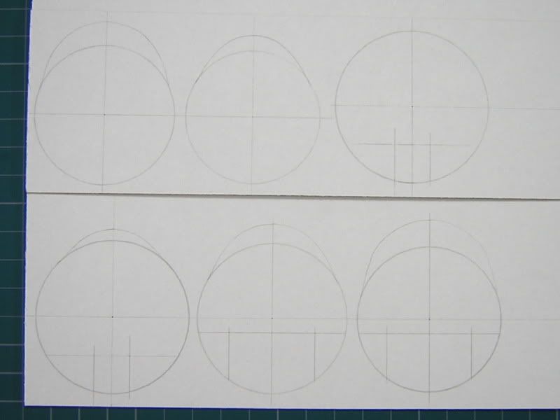 A 1mm dia. hole were torn at the center of a fuselage, which is used to check the alignment of the one during assembly.  A transparent cockpit window assembly using a former with heating up was not made since I wanted to make inner frames of cockpit windows where was installed some switch panels, an ovehead console, ceilings and so on. I will make the interior of both the cockpit and the navigator/nose gunner station only. I forgot to take a pic of the cockpit floor. The white plastic pipe which can be seen in the first pic (Upper = Aft, Lower = Fwd) has a dia of 1.6mm and it was added to increase rigidity on the center hole.    The forward nose gear well has been painted in green.   The LH two stuff in the pic is the side consoles of the cockpit. The upper one which is in the folded state is the LH console and the other that is in the flat state is the RH one. The RH stuff in the pic is the overhead console.  Again, I appreciate all the comments, input and so on from you!! Last edited by aki; 06-22-2008 at 08:20 AM. 
|
| Google Adsense |
|
#2
06-22-2008, 08:37 AM
|
||||
|
||||
|
Welcome! Hope you enjoy your stay here. We are all very supportive, and willing to help if we can.
It looks like you're well on your way. Good luck, and excellent choice of subject. I love this plane :D
|
|
#5
06-22-2008, 01:19 PM
|
||||
|
||||
|
This large project looks good so far. Very good technique, clean and accurate work, and some innovative techniques. I have had very little success making clean and accurate cuts in corrugated card and am impressed with the work you have done.
Don
|
| Google Adsense |
|
#6
06-22-2008, 10:51 PM
|
||||
|
||||
|
A 1/72 B-36................ geez......... I know I could not do that because my better half would crash it into me after it was completed............... then I would have to explain to the doc why I have all that cardboard in the wrong places..........never mind all the paper cuts:o
Truly you must be going to hang this baby from the rafters............. john
|
|
#8
07-06-2008, 08:28 AM
|
||||
|
||||
|
Thanks for the welcome and replies. I decided to get done the nose landing gear first as a few materials (books and the T.O.) what I've been placing the order to make the interior had not arrived on earth.
 I got started the tires first. I think there're several way to make a tire though, I tried the one as follows since I wanted make the grooves on a tread surface at least (There're eight grooves on the tire). The upper 16pcs which were made from a 0.2mm thickness sheet in the first pic are to be the groove portion. The middle 14pcs which have a thickness of 0.6mm and a larger diameter (1.0mm) than the upper 16 stuff are to be the tread portion of the tire. The lower 4pcs are to be a side wall (an outer side surface) of the tire.  The upper two stuff in the second pic are to the tread portion and the others are to be the side wall portion.  The up close side shot of the upper two stuff in the second pic. The grooves can be seen.  The up close side shot of the lower four stuff in the second pic. They are to be the side wall of the tire.  The places where are installed a wheel were cut out.  All the stuff have got together. You'll see that it's too square,... especially the side wall.   Both the tread and the side wall portions were ground to get a better appearance. I think you can see the eight grooves on the tread.   That's all for today..... BTW, wondering how long it'll take to finish?........... ")
|
 |
|
|


 Linear Mode

