
 |
|
#61
|
||||
|
||||
|
Thank you Yoav and Joe.
Hi Isaac. The plans called for two 1/8" (3mm) spars mounted through the fuselage. These connect into sleeves in the wing. I could have used wood dowels but because of the mass of that wing, did not think that the wood dowel would be strong enough in the long term. That is why I elected to use the aluminum tubing. 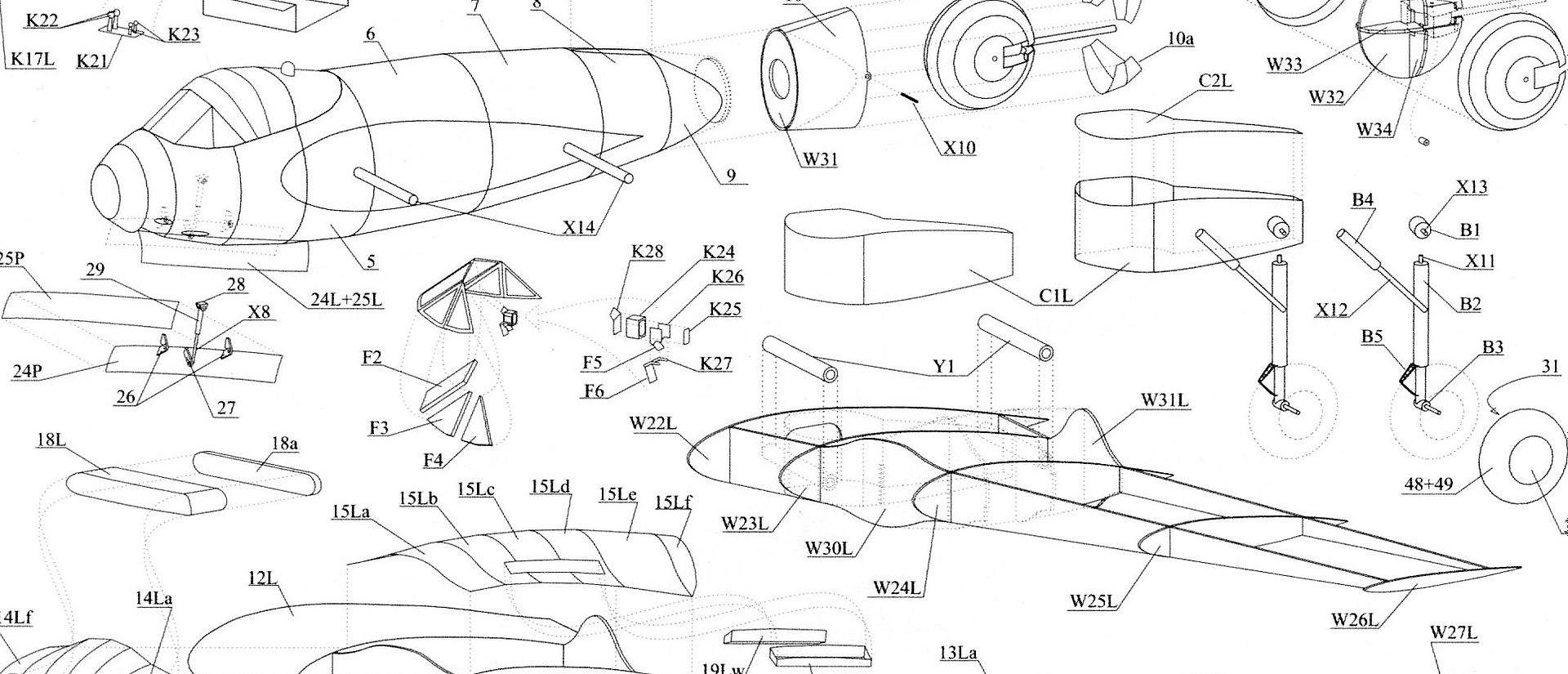 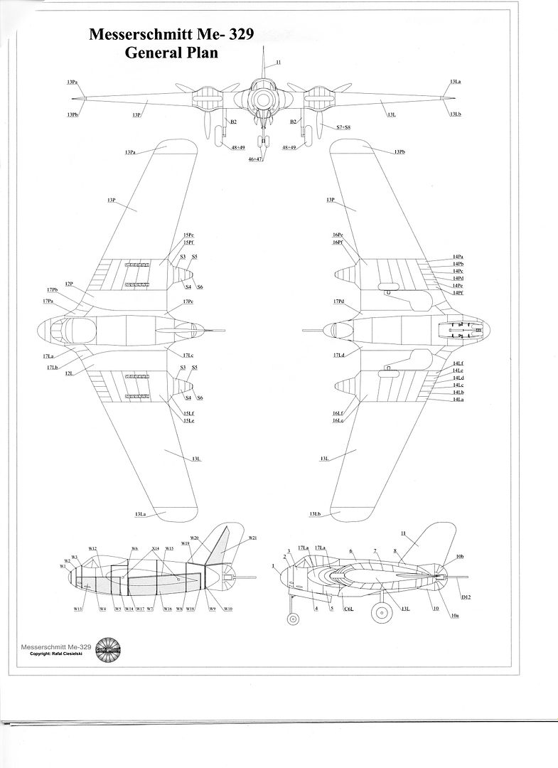 I hope that answers some of your questions. Jim |
|
#62
|
||||
|
||||
|
Great
Isaac
__________________
My gallery [http://www.papermodelers.com/gallery...v-r-6&cat=500] Recent builds  Meteor F1, Meteor F8, Mig-Ye8, NA Sabre, A-4E Skyhawk,Mig-15 red, Mig-17 repaint Meteor F1, Meteor F8, Mig-Ye8, NA Sabre, A-4E Skyhawk,Mig-15 red, Mig-17 repaint
|
|
#63
|
||||
|
||||
|
Your welcome Isaac.
Jim |
|
#64
|
||||
|
||||
|
Good evening.
Update time. I'm into the wings now. Cutout all the parts for the framework. 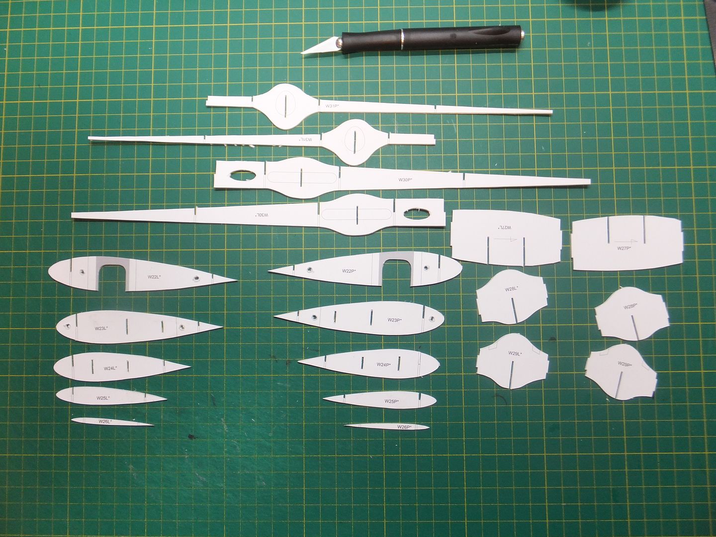 Started assembly of the engine nacelle framework first. Since this is a fairly rigid section, it will help square up the rest of the wing during assembly. 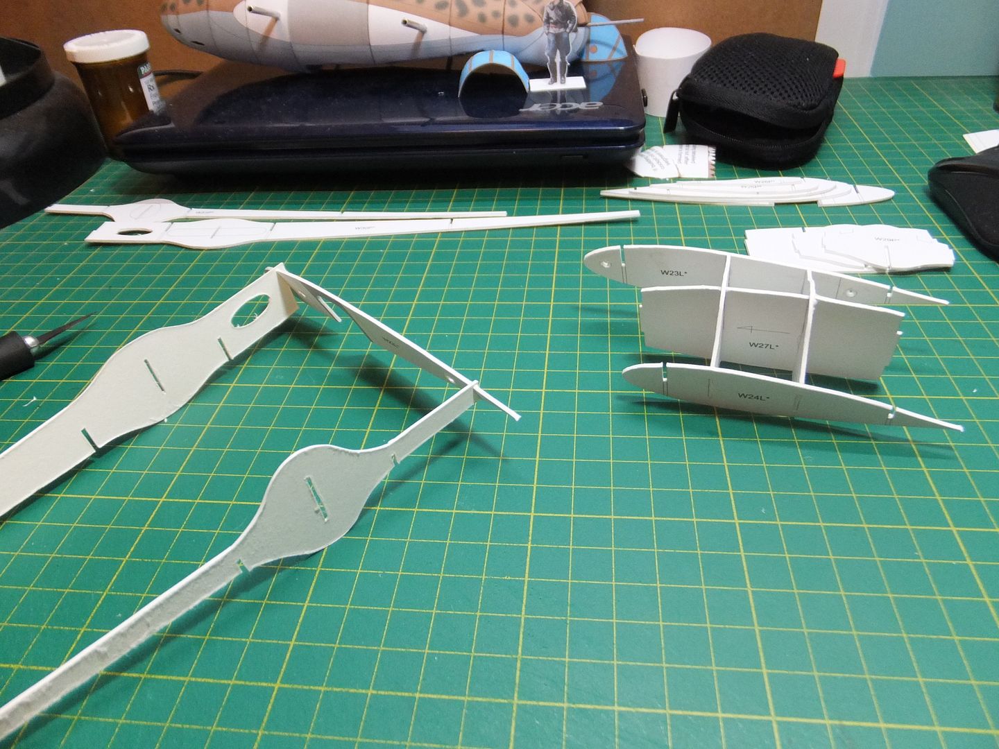 The wings framework went together quite easily. With the frames assembled, the mounting tubes for the spars from the fuselage were rolled and installed. Used a piece of the aluminum tubing for the core dia. and as an installation guide. I just had to slip the wings on to see how she looks. 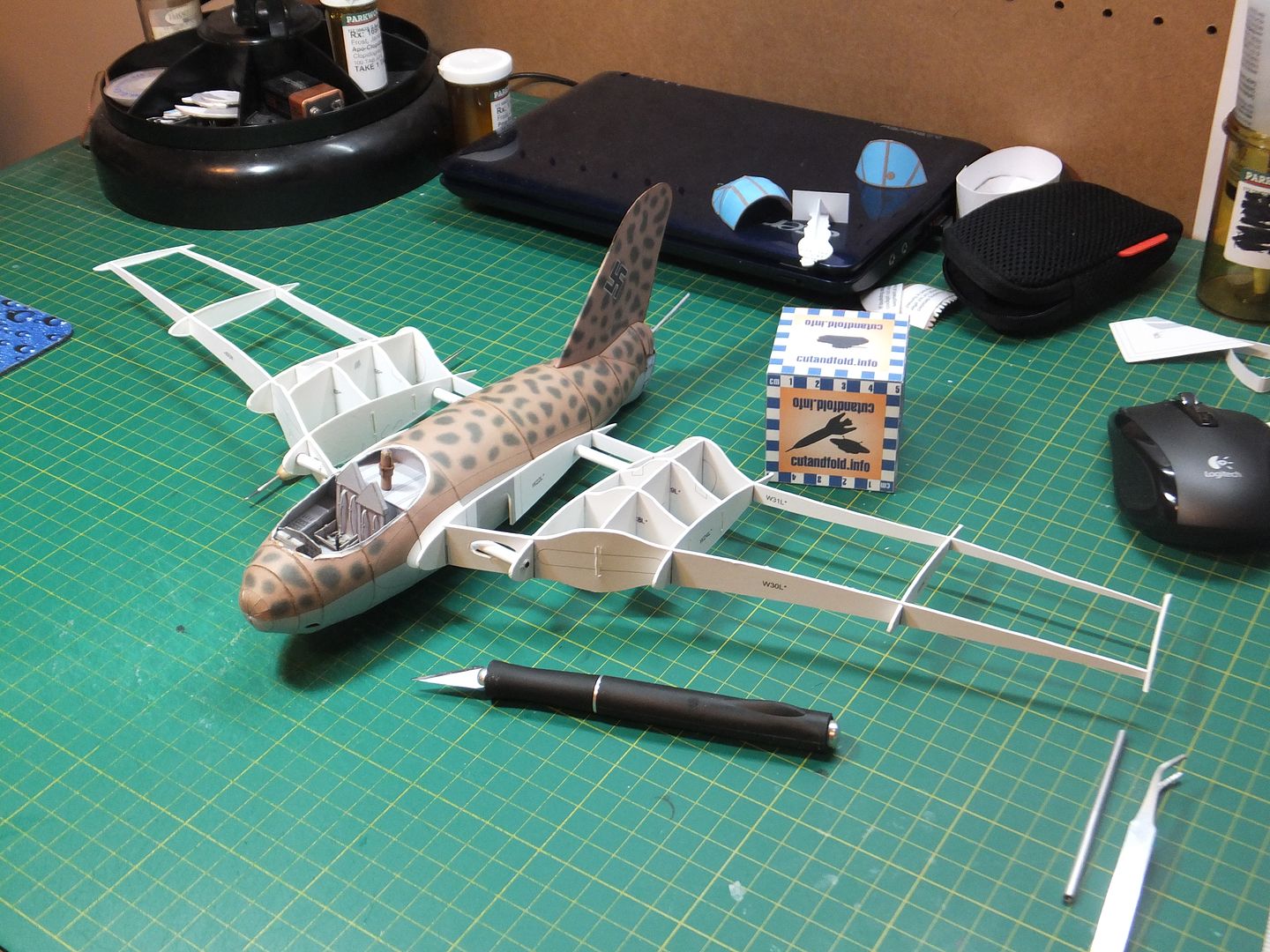 Since I will be installing the engines in the wings, most of the core of the engine nacelle will be cutout. Not until the engine covers and the lower nacelle skins are shaped and assembled first. Today I received the vacuform box and supplies I ordered. 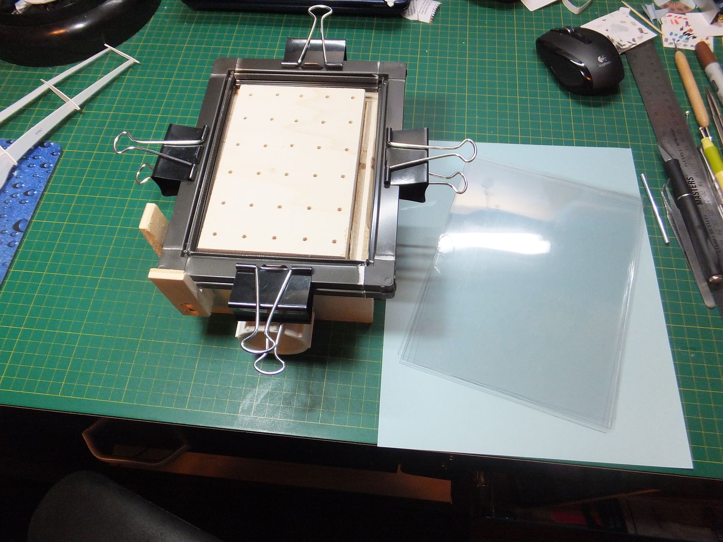 Will soon get around to making the canopy for this craft. Thank you for following. Jim |
|
#65
|
||||
|
||||
|
Jim
First, great pictures of the wing frames. That is very clear to see now. It will be helpful for us all who may build this plane ( I plan to do it as I have the laser cut frames for it as well ). Second, glad you got the vacuform box. I purchased the same unit. The guy on the phone should you need his help is extremely helpful. I talked to him from Japan when I was screwing up my canopies ). Let us know step by step your canopy mold ( plug ) making as well as the actual canopy vacuform making. Great progress so far. I'm still not settled yet in the USA, and am traveling. I hope to set up shop in a few months. I'm itching to build!!!!!!!!!!!!!!!!!!!! Isaac
__________________
My gallery [http://www.papermodelers.com/gallery...v-r-6&cat=500] Recent builds  Meteor F1, Meteor F8, Mig-Ye8, NA Sabre, A-4E Skyhawk,Mig-15 red, Mig-17 repaint Meteor F1, Meteor F8, Mig-Ye8, NA Sabre, A-4E Skyhawk,Mig-15 red, Mig-17 repaint
|
| Google Adsense |
|
#66
|
||||
|
||||
|
Thank you Isaac.
I have built the mold for the plug and just need to cast it. I plan on documenting the process. I'm looking forward to your next build. Jim |
|
#67
|
||||
|
||||
|
Update on the Me-329 build.
Next up I decided to install the landing gear bays in the wings. The drawings are not specific on their installation so there was a bit of dry fitting required before being glued down. Glued the back of the bay in first, leveling the top of the bay with the ribs. Then edge glue the open side of the wheel bay to the first rib. When dry the open side of the landing gear bays were trimmed level with the 1st and 2nd ribs. 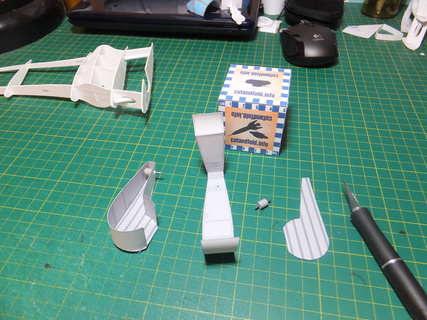 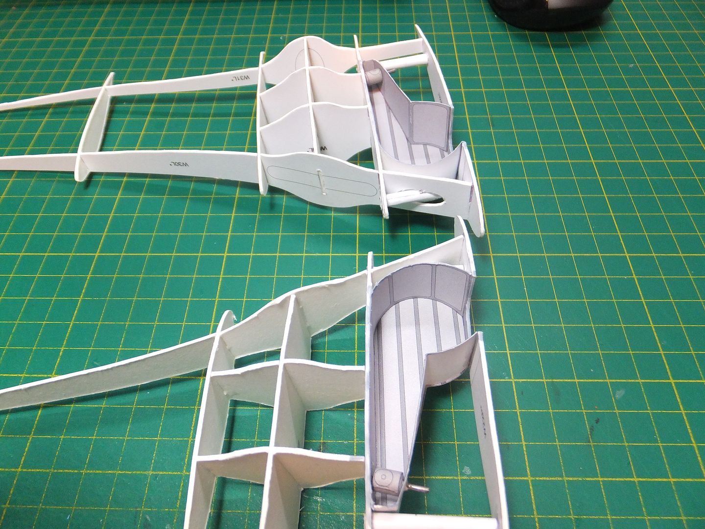 Upon studying the build of the skins over the engine nacelles, I found that the engines will have to be in place before those skins can be installed. So backtrack a bit. Those formers in the engine bay have to come out, but they still need to be preserved in order to shape the covering skins. Carefully those formers were cutout and the inside surfaces smoothed. At this stage the opening for the propshaft was cut out, and then the liner skins for the engine bay were installed. 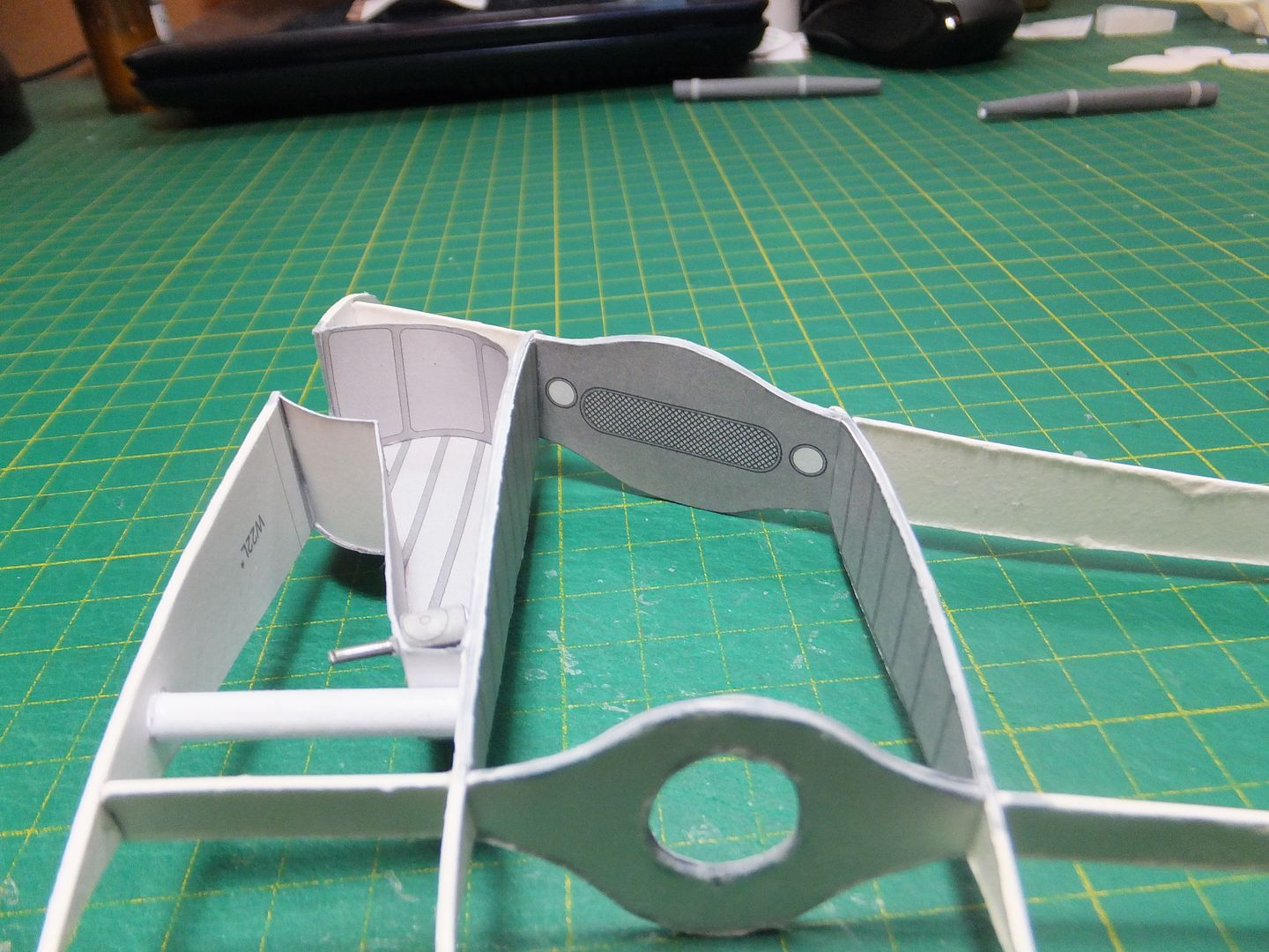 Working with the left engine bay first, started working on constructing the coolant jackets. Now they were not marked which pair were left and which were right. Figures the one that got built first was for the right side. Marked the printout and then built the proper left one. 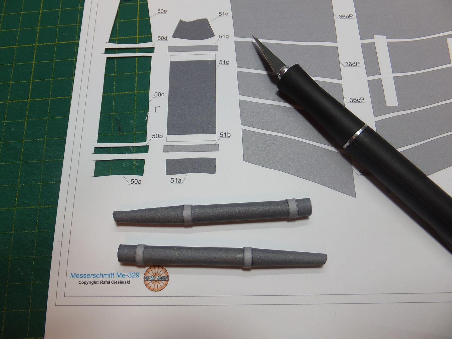 With both left bay coolant jackets built and installed. It was time to do the right side. 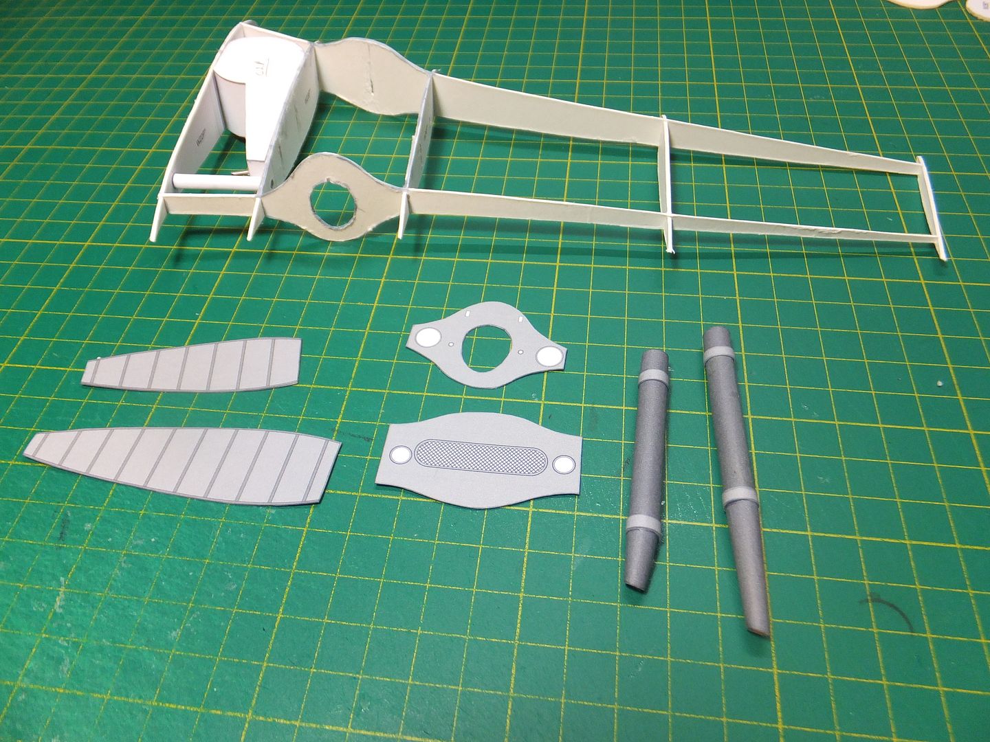 These jackets are about 1.5mm too long and need to be trimmed to fit. With the coolant jackets in, the radiators were constructed and installed into the front of the wings. 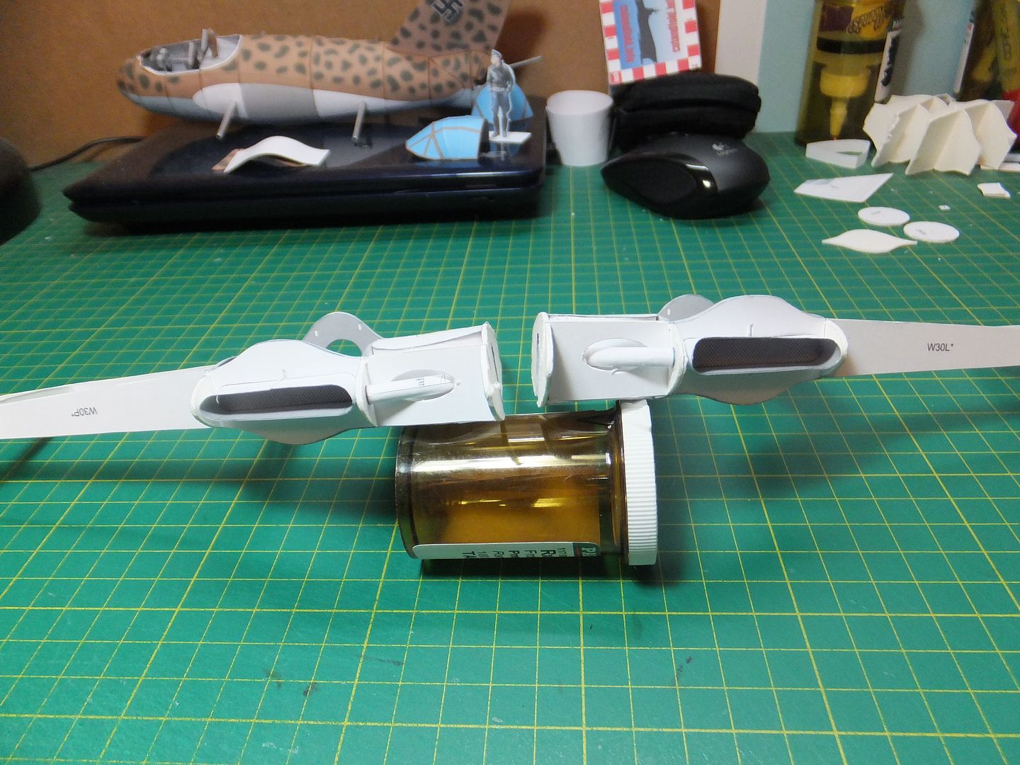 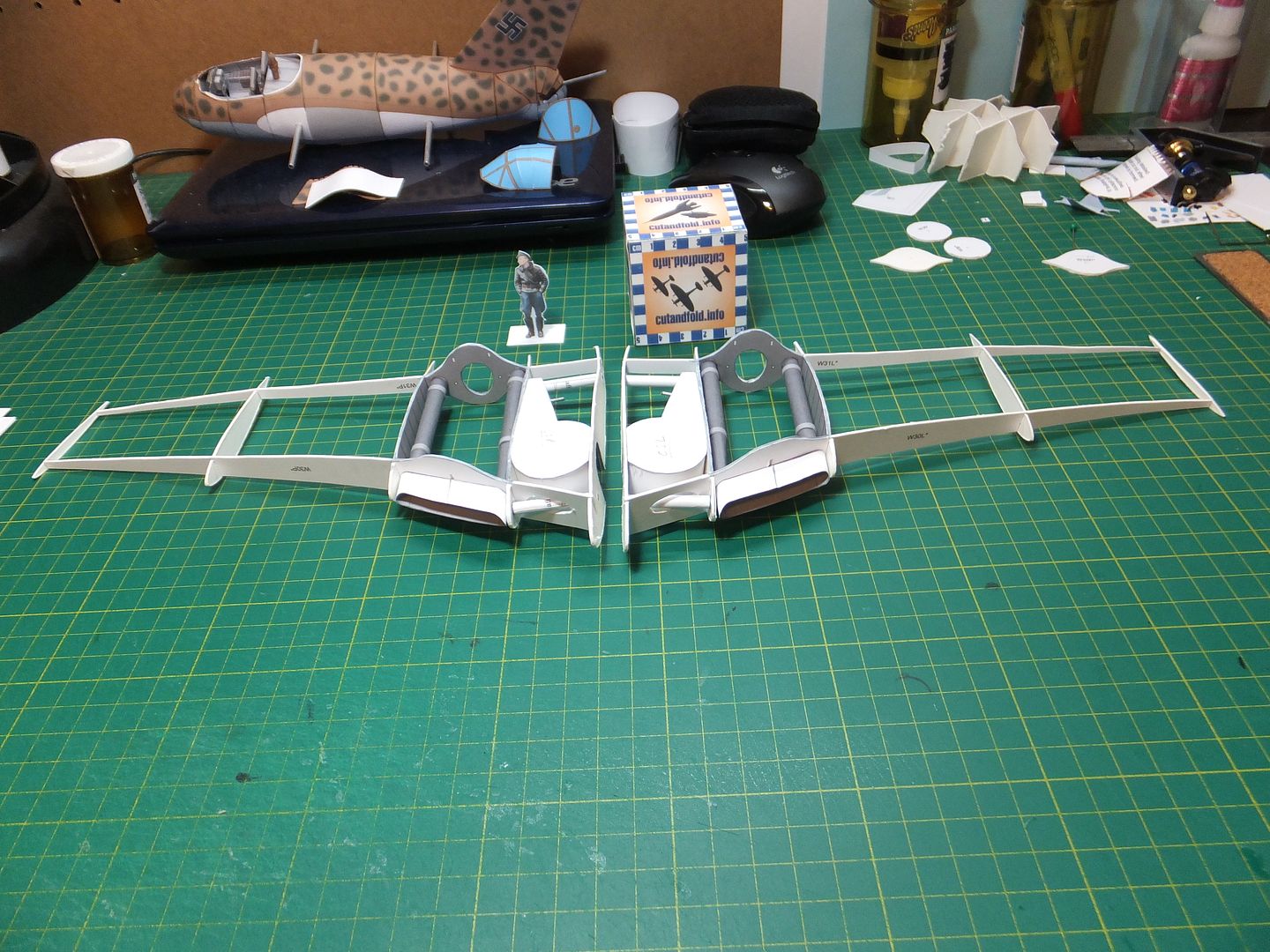 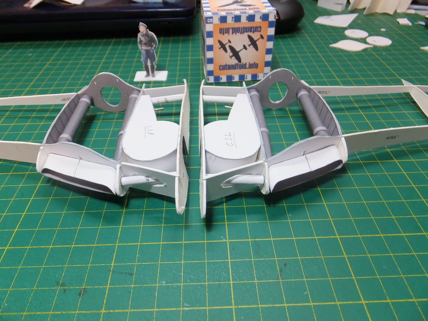 The engine mounts were next. The main part of the mount is double laminated card and the support brace is steel wire. With the mounts built, they have to be mounted onto the back bulkhead of the engine bay. Two holes are drilled into the back bulkhead to accept the support brace and the whole assembly is glued into place. There is is a small strap that holds the brace in position to the mount, they could have been longer but was able to make them work. 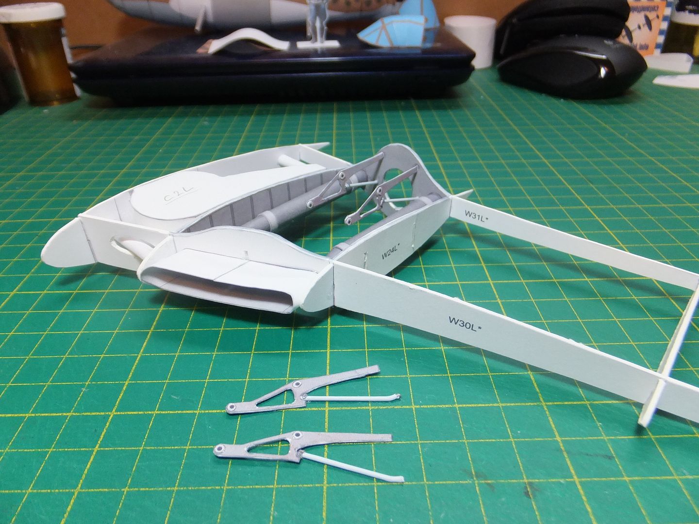 With the engine mounts in, it was time to move on to the engines. There are a fair amount of pieces to these DB-603 engines and not all the pieces are shown in the assembly drawing. Had to resort to actual pictures of these engines to verify some of their locations. The main block consists of two pieces. 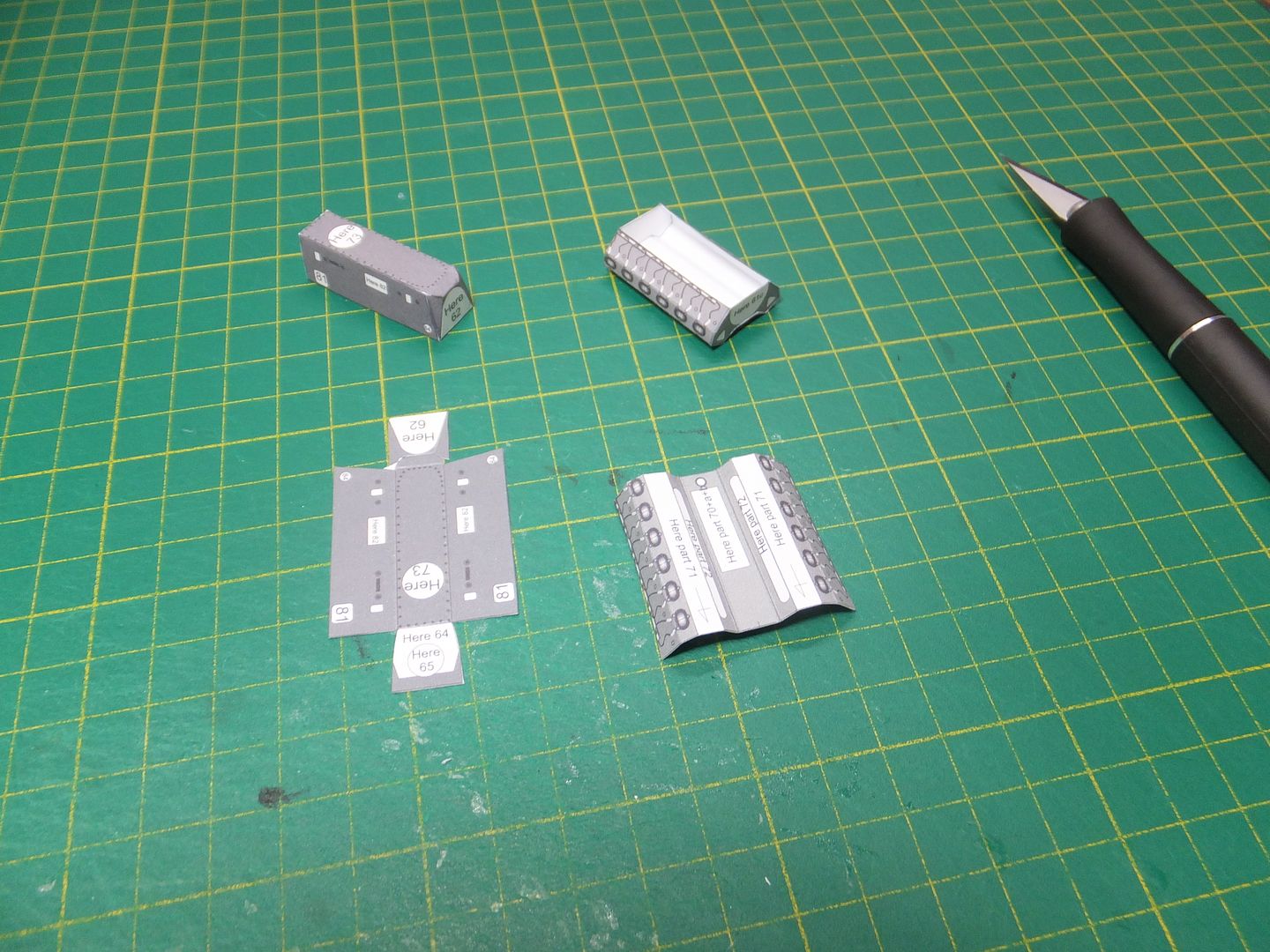 When trying to assemble these two pieces together, I found that the side walls of the lower block were too flimsy and hard to line up with the top block. What I did was print off another copy of the engine and cut out one of the end pieces used for the lower block and installed it in the centre of the lower block. this strengthened the whole unit and made it a lot easier to install the top block. With the main blocks assembled, worked on constructing and installing the drive units. I have one drive unit complete at this time. 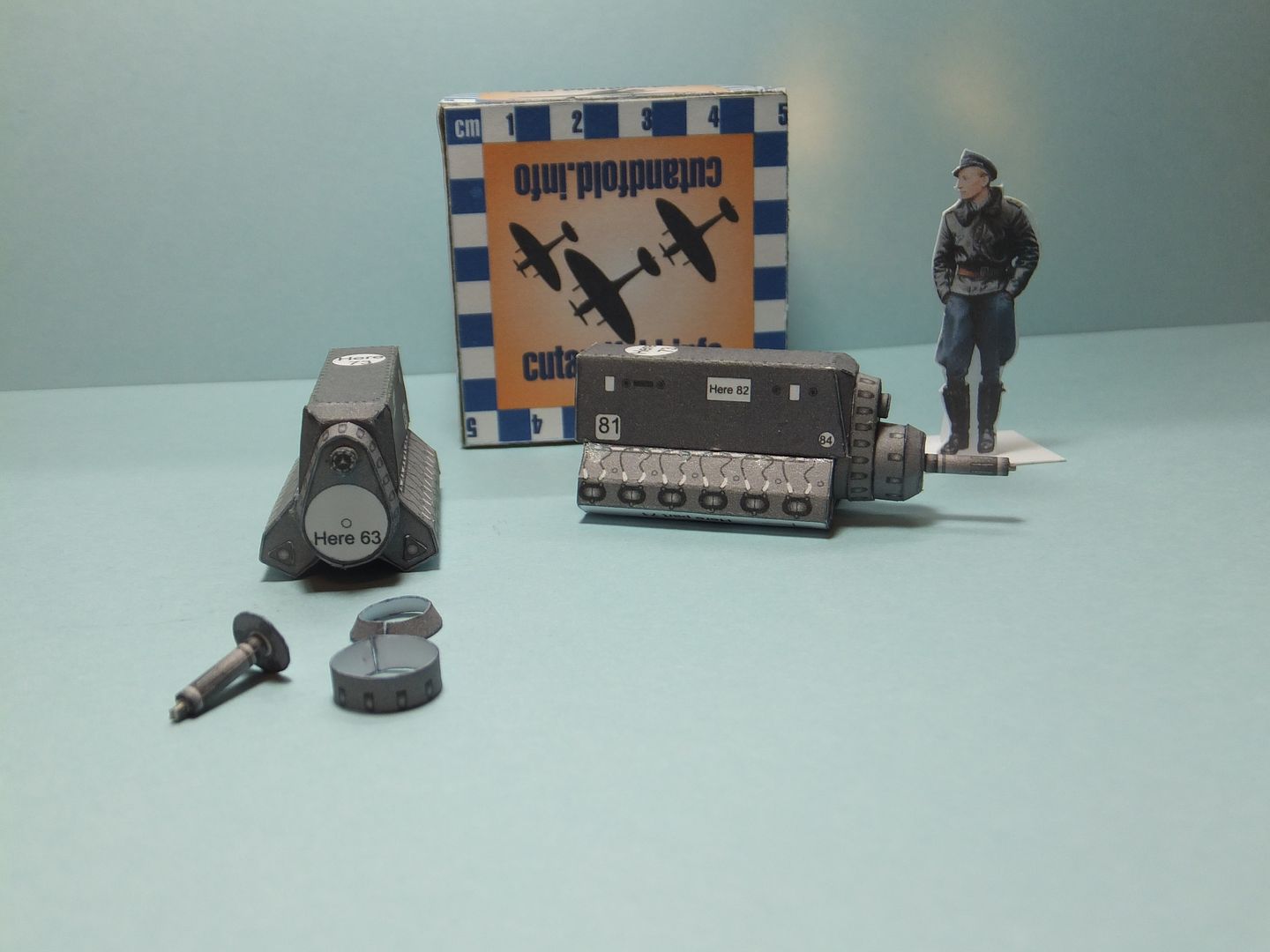 Still more parts to add to these engines before they are complete. Thank you for following. Questions and comments welcome. Jim |
|
#68
|
||||
|
||||
|
Wow, huge update, Jim. All looks mighty fine. Love the engines!
JoeG
__________________
Currently building Heinkel Models/Ron Miller Authentic Nautilus. |
|
#69
|
||||
|
||||
|
Thank you Joe.
It has been a busy week and got a bit behind on my posts. I love the engines too. They are like a model build just in themselves. Jim |
|
#70
|
|||
|
|||
|
Couple of observations:
- There's something distinctly submarine-like about this aircraft - possibly the tubby rounded fuselage and 'dogfish' camouflage scheme as well as the rear gun fairing being reminiscent of a shell. - The landing gear is massive, if it will indeed fill the entire bays when built. I can't imagine this helped the handling characteristics of what is already a difficult airframe, especially at low speed. - The 'pusher' propeller arrangement on this aircraft was a clearly a practical solution to fitting the propulsion units into a swept wing. With the engines mounted the conventional way round the propellers and engines would have needed to have stuck out so far in front to make the plane incredibly nose-heavy, not to mention obstructing access to the cockpit. - The periscope arrangement for the rear gun seems odd. Was the navigator seriously expected to crane his neck 180 degrees whilst strapped in (and likely in the middle of combat manoeuvres) in order to use the tube behind him or was there a further mirror from this which was placed in front? |
| Google Adsense |
 |
|
|