


|
|
|
#11
 07-14-2014, 05:40 AM
|
||||
|
||||
|
Great step-by-step instuctional. Very helpful to the novice as well as the more experienced builder.
__________________
Regards, Don I don't always build models, but when I do... I prefer paper. Keep your scissors sharp, my friends. 
|
|
#12
07-14-2014, 07:03 AM
|
||||
|
||||
|
Looking really great, Dave. Masterful work on the wheel housings.
__________________
Currently building Heinkel Models/Ron Miller Authentic Nautilus.
|
|
#14
07-14-2014, 08:51 AM
|
||||
|
||||
|
Thanks Joe (and all)
This is the first time I did the wheel housings this way. (I think this is the fourth time for me assembling these parts) This is the first time I cut one slit and overlapped the join. It works...its a little easier...but its the last time I will do it this way. I prefer the smoother effect of a flat, edge join petal. (like what I did on the Golden Hawk build below) There is no way to hide the joins in the petals (without putty and paint) but edge joining gives you a smoother effect that seems to help hide the joints a little more. Thats what I think anyway. 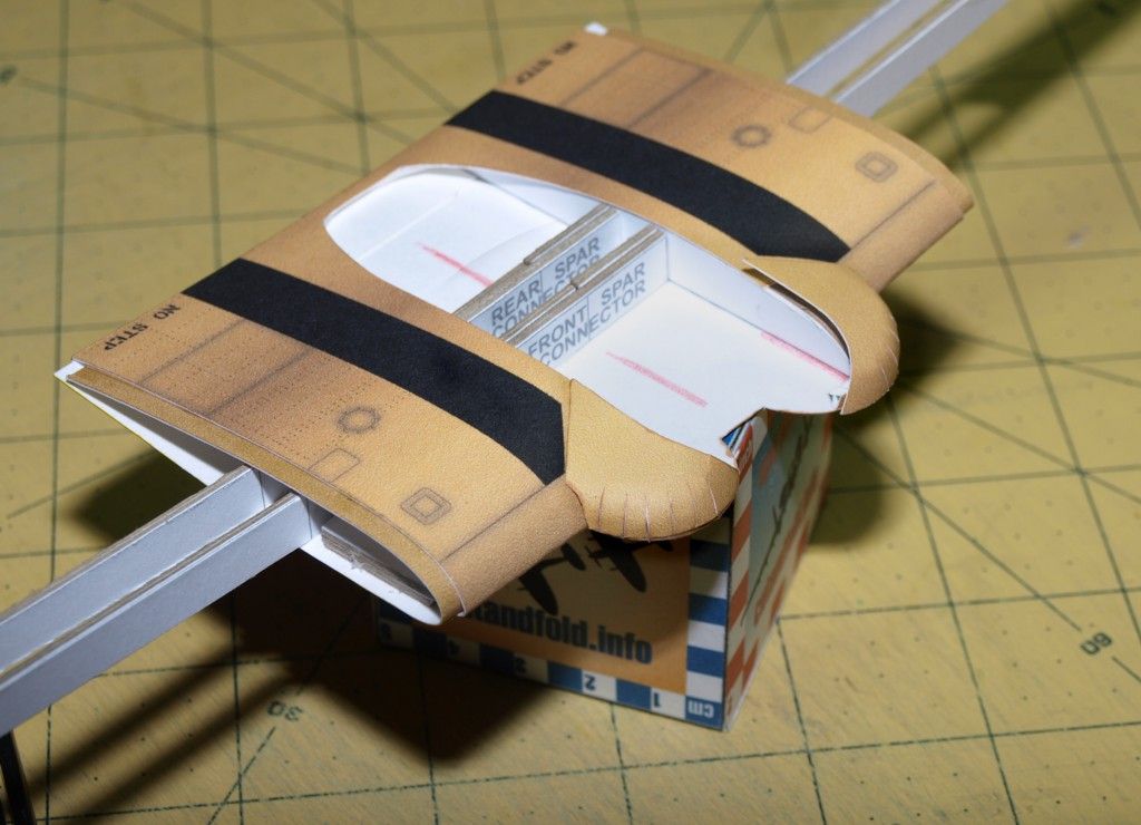
__________________
SUPPORT ME PLEASE: PaperModelShop Or, my models at ecardmodels: Dave'sCardCreations
|
|
#15
07-14-2014, 09:07 AM
|
||||
|
||||
|
Thanks Dave, I really appreciate you showing such detailed instructions on the wing.
Gary
__________________
"Fast is fine, but accuracy is everything" - Wyatt Earp Design Group Alpha https://ecardmodels.com/vendors/design-group-alpha
|
| Google Adsense |
|
#16
07-17-2014, 01:13 PM
|
||||
|
||||
|
Okay, so moving on to the fuselage...
I start with the set of formers that I prepared earlier by laminating to 1mm (layers) card. There are five formers for the fuselage plus one for the engine cowling. 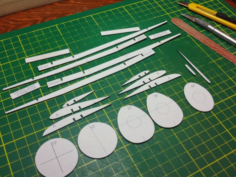 ... I need to also prepare the two central formers that fit into the cockpit. The central former has a front and rear facing layer to be attached. (In the following photo the rear facing part has no artwork. Normally you would see a Co-Pilot's Instrument panel.) The front former will carry the Pilot's Instrument panel, but it can be attached after installing the former in the fuselage (and before the Cockpit tub goes in). Just make sure you fit the part to the former and check the shape and size. Adjust if necessary. 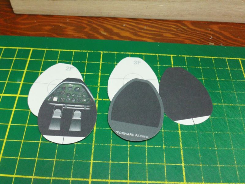 ... Cut out all the fuselage parts...and the tabbed joiner strips. I like to check out the order and placement, maybe get a rough idea of what goes where and why. You can also check some fit and look for any printing or cutting errors. 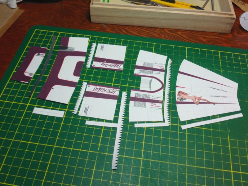 ... First thing I do is attach the central (belly) seam joiners. Sometimes they are separate pieces, and sometimes they may be attached to the section joiner strips. I also start rolling the parts into a rough approximation of what they should be. Just refer to the formers for the proper shape of each section. The more they are pre-shaped, the easier the assembly will be. You'll notice I used a pair of self-clamping tweezers to hold the seam on the tail end part. Its a small radius part and a little trickier to glue. I use flat tweezers (no grippy teeth), as well as clamps of various sorts, to hold parts while the glue dries. 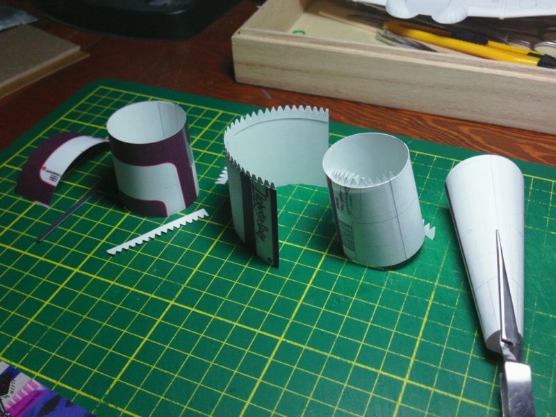 ... Parts are rolled and secured at the central (belly) seams...I give the glue plenty of time to set up... and then complete the installation of the tabbed joiner strips. Because the inside diamter of tubes and rolled parts is smaller and tighter, you don't want to glue the strips into place after the part has been rolled and glued into a tubular section. 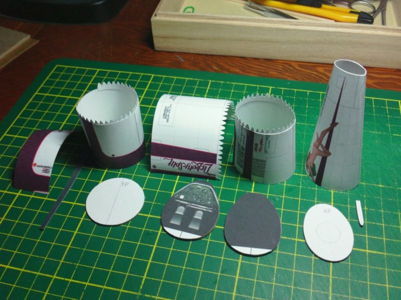
__________________
SUPPORT ME PLEASE: PaperModelShop Or, my models at ecardmodels: Dave'sCardCreations
|
|
#17
07-17-2014, 01:14 PM
|
||||
|
||||
|
The smallest former is a tricky fit into the tail end of the fuselage.
Its best to pre-shape the fuselage part as much as possible before trying to glue in the former. I use a small dowel and my fingers to shape the part...but you also have to keep a firm grip on the part so it stays in that squashed state until you get the former glued into place. 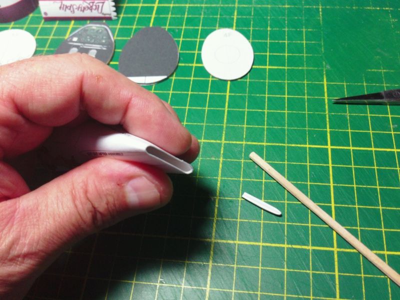 ... Use a clamp or self-clamping tweezers to hold the part securely until the glued former is secure. Theres a fair bit of tension on this part at this point, so it wants to pull apart. Try not to crush the tail with your clamp...as I did a little bit with my tweezers! 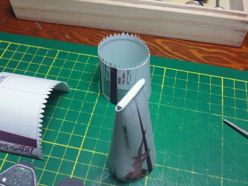 ... Continuing with the tail section of the fuselage, I attach it to the next fuselage section. I like to work from the ends of the fuselage...ending up in the middle (as my last connection). Note: the part shown does not have a full cutout for the rear cockpit. This is a design element of this particular aircraft, and does not apply to all Texan models. Slip the second to last section over the glue tabs and glue in place. Once again you will need to hold the part in the proper shape to keep the tension off the tail and make it easier to install the next section. The next section will not fit correctly and tightly if it is not in the correct shape (because of the curved end surfaces). Some may choose to install the former (4F) into the tail part first. I prefer to slip the formers in afterwards...but thats my personal method. If the former is in place, it will solve the problem holding the shape, but make sure the former is not too tight, otherwise it will make it more difficult to connect the next section. 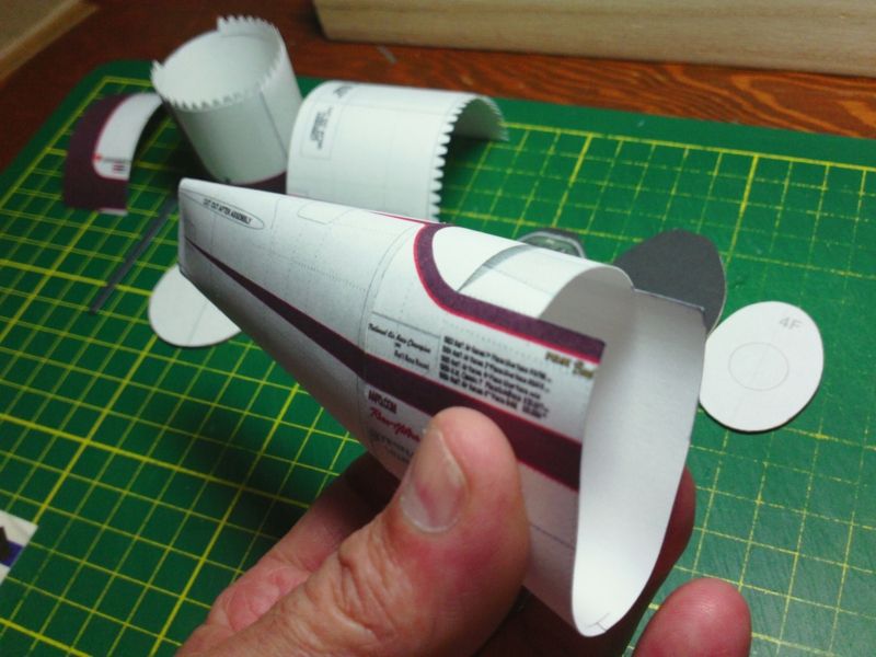 ... As I said, my method is to slip Formers in after the connections are made. I find it easier to shape the former down to a snug, but relaxed fit and then slide it into the fuselage. Gluing it in place at the tab strip. Depending on the depth of the former's position or how much access I have, I might make holes in the former so I can use tweezers or pliers to fit the former. I will often put pencil marks on the inside of the parts, marking the top and belly seams. This helps when positioning the formers. 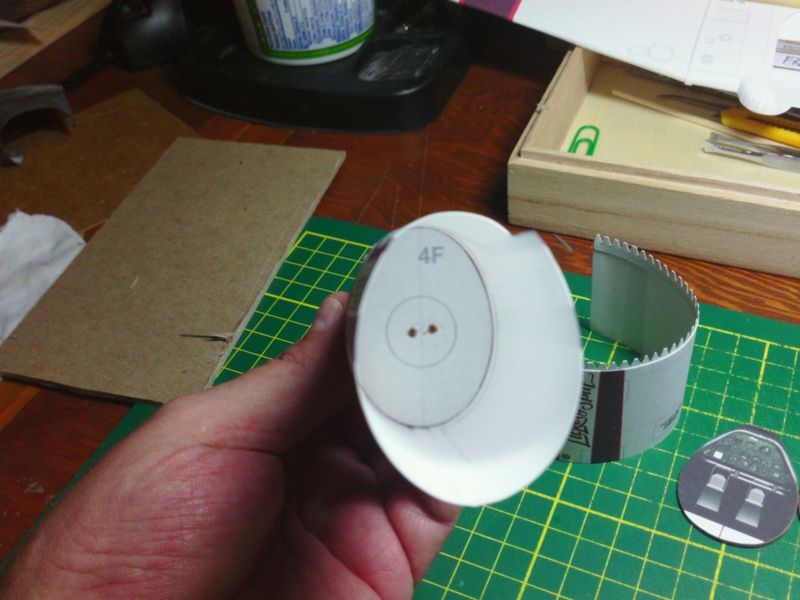 ...
__________________
SUPPORT ME PLEASE: PaperModelShop Or, my models at ecardmodels: Dave'sCardCreations
|
|
#18
07-17-2014, 01:14 PM
|
||||
|
||||
|
So, now moving to the opposite end of the fuselage...the front....
I slip the front most former into place. This one is almost perfectly round and installs flush with the forward edge. (Its not important which side is visible, since it will eventually be hidden by the engine cowling). 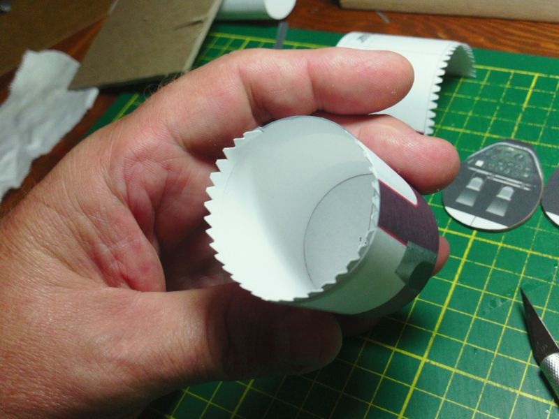 ... Then, just like with the tail, I attach the next section to the first. This one is nice and open because of the cockpit cutout, so its easy to get a smooth and clean connection. The trick is take your time...glue small areas at a time, wait for them to dry and then glue more. Work your way around a part and you can shape as you go, getting the best fit possible. BUT...always dry fit the parts first. Check the fit, the position, the size, etc. Make sure it works and get a better understanding of how it will go together. Then glue it up and make a mess. 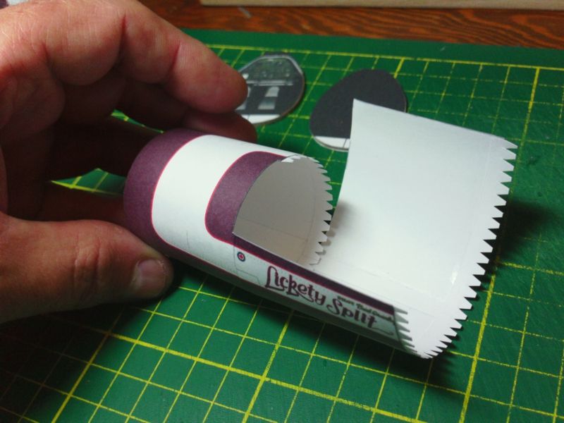 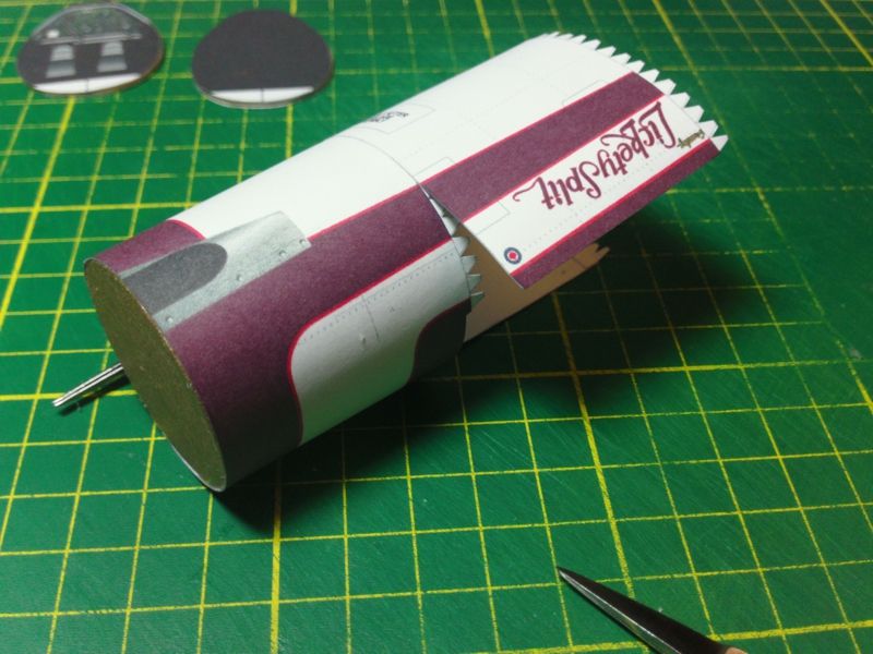 ... It is at this point that I made a big mistake with my assembly. Because I was checking parts and watching for problems (from a design point of view), I went ahead and installed the upper Instrument cowling...instead of continuing with the assembly of the fuselage sections. On this model the Instrument cowling is part of the forward fuselage and it must be in place before you can install the front fuselage cowlings. I wanted to check the fit and artwork of those cowlings. With the instrument cowling on, I will not be able to install the cockpit formers, or the cockpit tubs...so I will have to cut this part off again. 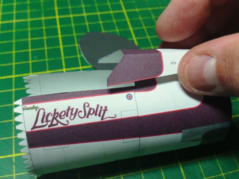 ... So, back to normal procedures: I have two halves of a fuselage, and I can connect them in the middle. And once again, because the last connection is at the open cockpit area, I have more access to to connection from inside and outside...allowing me to glue it carefully and cleanly. Its always important to keep an eye on belly seams and edges, to make sure they continue to line up. 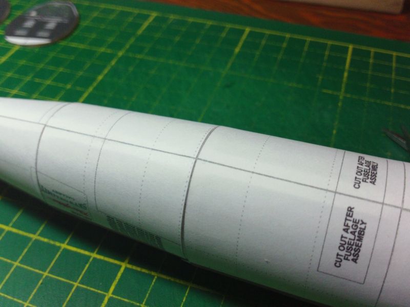 ... So, had I not sidetracked with the upper cowling installation, the fuselage assembly would have been at this stage: 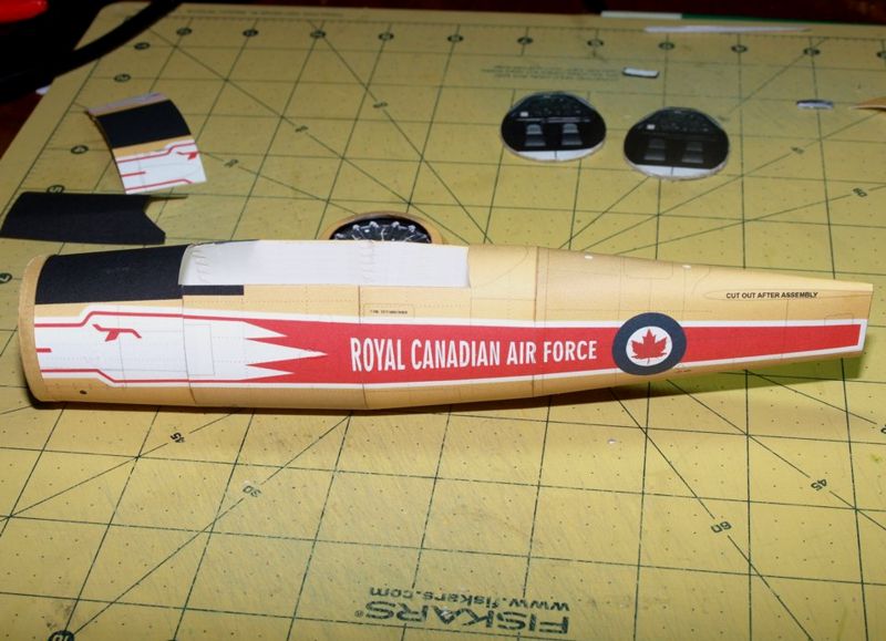
__________________
SUPPORT ME PLEASE: PaperModelShop Or, my models at ecardmodels: Dave'sCardCreations
|
|
#19
07-17-2014, 01:51 PM
|
||||
|
||||
|
Next step is to install the front former...the one with the Pilot's Instrument panel.
When looking at the following photo, you must pretend that the upper cowling is not in place...sorry. As I mentioned, you can wait until after the former is installed to affix the Instrument panel artwork. Position the former directly over the seam. There is a little cutout in the upper surface of the fuselage which will help position the former. (It extends beyond the fuselage to be covered by the cowling.)  ... Once the front former is in place, we can drop in the cockpit tubs and the center (and last) former. Normally, I would drop the front tub in place...tight to the forward former. Then the central former, which should be at the central seam. And then squeeze in the rear cockpit tub. But on this particular build, part of the rear cockpit is opening is blocked, so I will have to put the rear tub in first. Anyway, lets build the cockpit tubs first... Start by scoring all the fold lines...ready to fold...and then cut out the two tub parts. 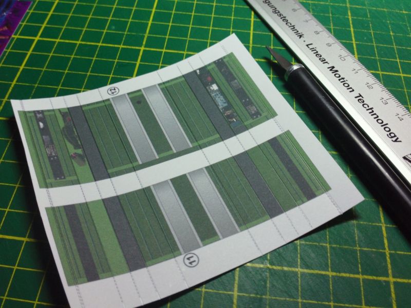 ... The top edges of each tub are intended to fold down, so I like to leave a little extra material.  ... I also cut some spacers that i will glue under the top edge for strength. 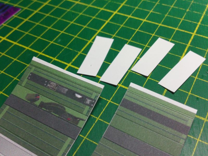 ... You have prescored, so bend the top edge flaps into shape. I use a metal rule to make the squared fold at the top edge of each tub side. 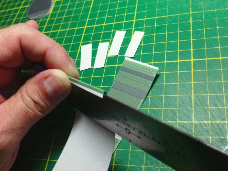 ... Now glue in those cardstock spacers...two layers should do it. 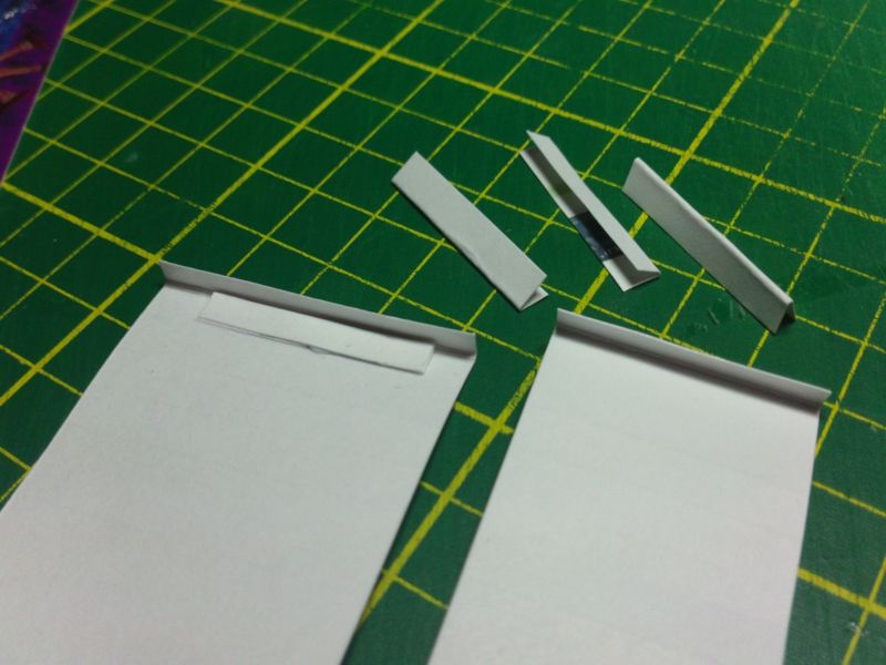 ... And fold down, and glue, the top edge flaps. This gives you a thicker edge to glue to the cockpit sides (of the fuselage) and gives you a stiffer, stronger upper edge to the cockpit tubs. 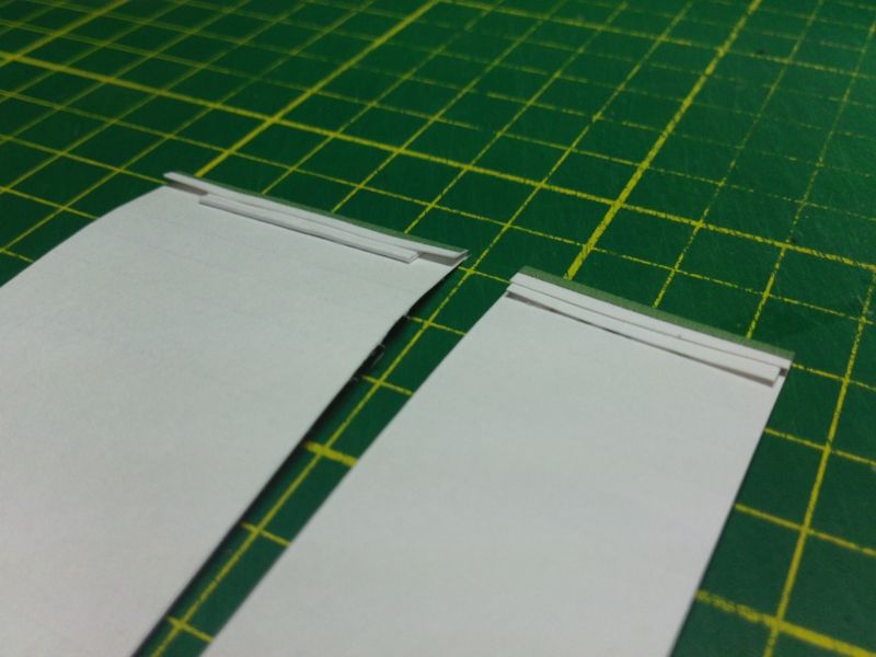
__________________
SUPPORT ME PLEASE: PaperModelShop Or, my models at ecardmodels: Dave'sCardCreations
|
|
#20
07-17-2014, 01:52 PM
|
||||
|
||||
|
Cockpit tubs continued...
now fold the side "shelves"...three creases and glue the accordian section to form a shelf on either side of the Cockpit tub. (Not visible on this print) are small triangular cutouts under each shelf part...slice them, fold them out and create little support brackets for the side shelves. 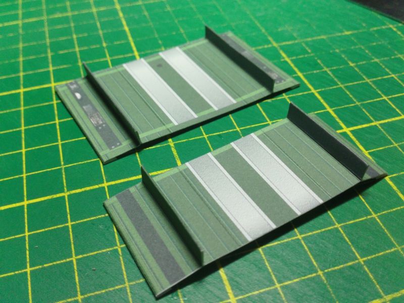 ... And lastly, the folds at the floor... and this creates the "tub" that you will drop into the fuselage. I suggest you install the Seat(s) and Control Stick(s) later, after the tubs are installed in the fuselage. 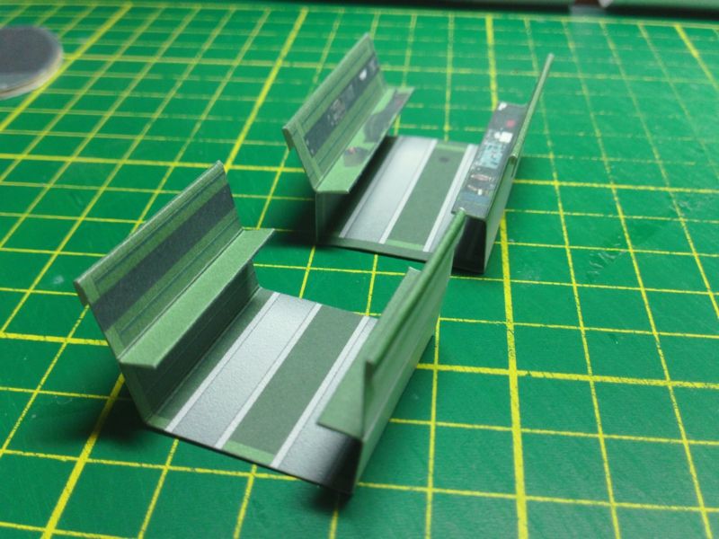 ... Drop in a "tub" and line up the top edges with the cut out opening in the fuselage. You only need to glue along this top edge, making sure the tub is carefully aligned with that edge. Then fit the central former into place...it should fall at the center fusleage seam. Just make sure there is enough room for the front tub to fit in. It doesn't have to fit tight against the formers, but it does have to fit. The center former is just aligned vertical, and centered, and held down firmly into the fuselage. Glue the bottom in place first...and then apply a small amount of glue on the sides to hold the fuselage sides securely.  ... The center former is then hidden from view by a cover which also acts as the Instrument Cowling for the rear cockpit panel (not used on this particular model shown). Assemble the cowling and center over the former...edges flush with the fuselage sides. 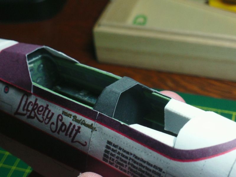 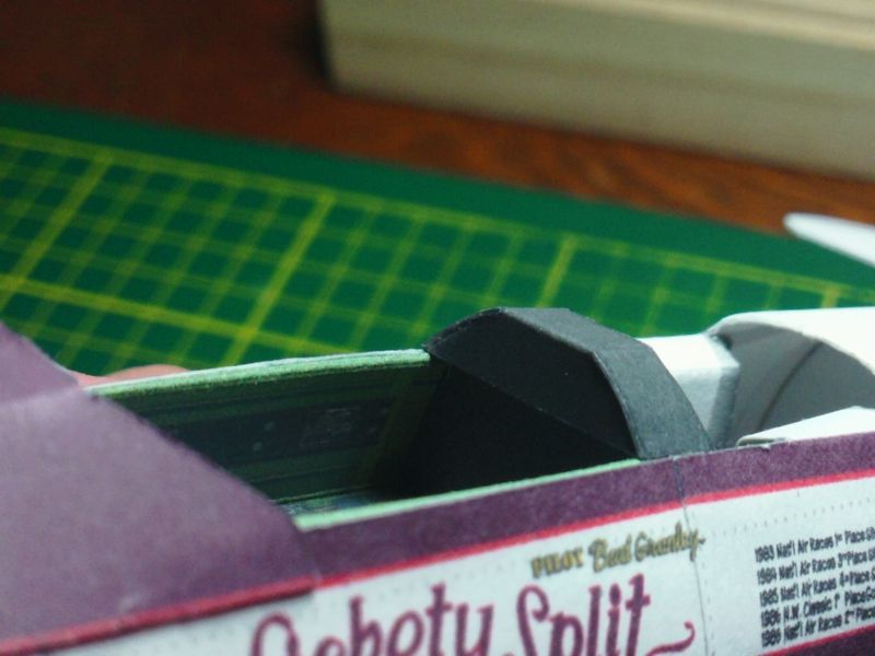 ... No, you can install that front cowling. Remember that front cowling? The one I had to slice off and then glue back on?
__________________
SUPPORT ME PLEASE: PaperModelShop Or, my models at ecardmodels: Dave'sCardCreations
|
| Google Adsense |
 |
|
|


 Linear Mode

