


|
|
|
#1
 06-25-2009, 03:06 AM
|
||||
|
||||
|
WOH 1/33 Ilya Murometz
Hi
This thread takes off where model review leaves off.... As covered in the initial review, the instructions are reasonably detailed but have a few gaps. I am hoping that the ICM 1/72 Ilya, even though of a later model will have a few clues as to things like the MG mounts, positions of spare magazines etc. That kit is somewhere in here: 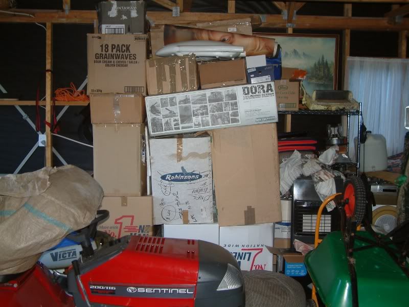 Unfortunately winter hit here when I was halfway through shifting my stash from the main house to the new hobby hut - which is not quite finished and being winter, most of the builders have cut away to warmer climes for a few months or have gone back to their ski-focussed day jobs...so until it is properly roofed and sealed up, the stash stays as you see it.With a bit of luck, the Murometz will be somewhere near the surface in an accessible box - Her Indoors has made it quite clear that the garage is NOT going to become the de facto modelling room any more than it is already.... 
|
| Google Adsense |
|
#2
06-25-2009, 07:19 AM
|
||||
|
||||
|
Here is the Sikorsky mock up at the Monino Museum. It was made in Latvia for a TV show and it is not original.
Originalfotos.7 http://aeroweb.lucia.it/rap/Monino/mon94js_muromets.jpg But it look nice... I am sure the real bomber it did not have plumbing pipe for the wing braces and landing carriage.
|
|
#3
06-27-2009, 08:53 PM
|
||||
|
||||
|
Thanks, Lala, it seems like most of the decent online pics of a Muromets come back to this replica. The Monino replica is also the Murometz that, so far, seems to be closest to the WOH model, apart from the nose gun.
I've spent quite a bit of time trying to find out more about the Sunbeam Arab engines on the Murometz B (as described in the instructions) only to find that the Arab was a V-8 not the straight 6 provided in the model. Ditto for the Salmson engines also listed for the B in the history in the front of the instructions; again not a straight 6 but a radial 9! Rather than get all AMS's up about this as I like to build for enjoyment, I'm not going to research this to death and am going to pretty much build from the box and just update/adjust where I can. If not, I will end up completely re-engineering the kit to the extent that I might as well scratch-build one. So the engines will be the straight 6s provided, and I have already decided to cheat on the cylinders and turn them out of wood to get the cooling fins uniform and straight. I would use aluminium (aluminum for wayward colonials) for the metal effect but am very wary of adding any more weight to the wings than necessary.
|
|
#4
07-19-2009, 04:44 AM
|
||||
|
||||
|
OK...I have been somewhat distracted from this build by the Modelik Udarnyj river monitor (build in the Maritime section) but started to get back on track tonight by spending an hours or so during Criminal Intent cutting out all the circle parts for the engine block.
|
|
#5
07-22-2009, 03:28 AM
|
||||
|
||||
|
Have started assembly of the first of four engine blocks...it's probably a good thing but I misplaced one of the end cap pieces and had to reprint the parts page. In doing so, I noticed that the colours coming out of the printer had a substantially different shade than the colours in the PDF file...very green. I had noticed the green shade from my first print run but had not thought into it too much but now it is apparent that there is a colour mismatch between my inkjet and the PDF file. I reprinted the sheet as a grey scale only and it came out OK so this build will NOT be a Jolly GREEN Giant:
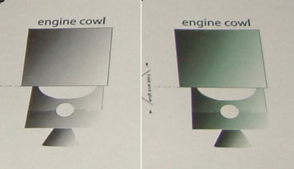 Here is a very poor shot (too much enlargement) of the green engine block. Observations on this part so far are that part ef4 which is the lengthways former is a mm too high and needs to be trimmed to be the same height as the ef3 lateral formers; and that e9 seems to be a mm too long at either end -m certainly when I trimmed off the extra, the end cap seemed to fit better; part e7 seems to be too long for the parts (ef2 and ef3) that it goes around. On 300gsm card these two parts' thickness is the same as the width of e7 so I laminated them before forming this part. 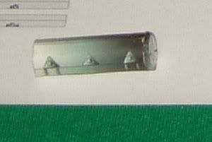 There are some additional parts still to be added to add some 3D to the triangular mounts on the side of the block. The exact relationship of parts is not very clear in the instructions so plan for some trial and error and maybe do a test build first to figure it before a production run of the four engines.
|
| Google Adsense |
|
#6
07-23-2009, 04:18 AM
|
||||
|
||||
|
Restarting the engines (in the right colour this time! Still can' believe I never thought to query the Deep Bronze Green tinge to the first lot of parts).
This pic shows from L-R, the height difference between former ef4 and ef3 - when ef4 is trimmed to match the fit is good; the engine block formers good to go - there are meant to be horizontal formers as well but I thought this was overkill as there is no load on the engine block so left them out - you can see that the engine block itself is slightly longer than the formers; and the first stage of the block complete before the end caps are added - I have used some spare ef3 parts to extend the formers to match the length of the block 'wrapper'. First time round I trimmed the excess off but think that the cylinders will fit better by working from the longer part. 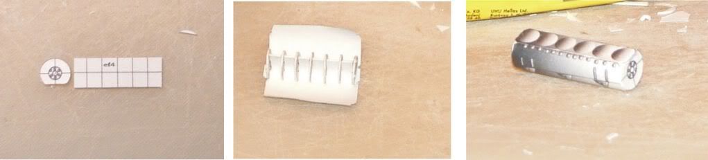 Quite a bit of guestimation is needed to work out the engine instructions and I am looking forward to some real fun fitting the exhausts....
|
|
#7
07-23-2009, 06:21 AM
|
||||
|
||||
|
I have that issue when I print the PDF Files for my Micromodels. I have found some time if I adjust things it print better or normal. But you can try to set the paper for some thing like "Matte Photo Paper" and printing for "High Quality". But you may have to try just "Plain Paper" etc. I find also if I cut and print a section of the file so I can print just some parts, then the section print differently than the whole file. Or if I also mirror the file to print it reverse, then the colors they shift then also. Very strange.
|
|
#8
07-27-2009, 03:54 AM
|
||||
|
||||
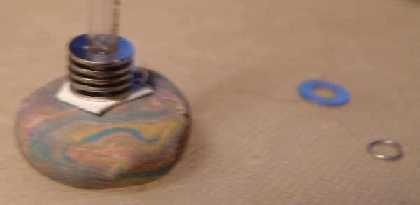 The ongoing adventures of the engine cylinders....option 1, of which I forget to take a picture, was the good old-fashioned approach of wrapping lengths of fuse wire around the cylinder cylinder that comes with the model - this looked more 3D than the original but the seam down the back was pretty noticeable. Option 2 was as previously mentioned, getting the cylinders turned out of wood but I forgot to ask the son-in-law (a joiner) to do this when I saw him on the weekend - this is still looking like the best option and he DOES want us to babysit this weekend. Option 3 was an experiment with some tiny washers I found in the hardware supplies on Saturday. They come in a sealed blister pack so I was unable to measure them before buying them, and the only measurement on them was the internal diameter when it is the external diameter than matters to me for this project. These were the smallest ones on the stand and as it turned out, are 7mm across when I need 6mm. Building a practice cylinder was still a good little exercise thought and I used the washers, fuse wire spacers and some 3mm plastic tube that I found in the spares box. If nothing else I now have 20 7mm washers that should be useful for something some day.... In other engine matters, I've just printed out the engine parts on metallic silver paper to see how that looks when complete. Just looking at the page now, it will be a cow to print as even the nightlight reflects really strongly from the surface so extra care necessary when cutting and scoring...
|
|
#9
07-28-2009, 04:46 PM
|
||||
|
||||
|
Glad to see you working on this one as well. Can not wait to see what you do with the engines. Great idea about washers for cylinder head fins. How on Earth did you find some sooo small.!!!!!
 Rick Rick
|
|
#10
07-28-2009, 05:54 PM
|
||||
|
||||
|
The completed cylinder looks quite good, albeit clearly oversize when placed on the engine block. I'm going to see if there are any smaller washers available (these were on a big stand in the builders' suppliers with a vast range of washers, nuts and bolts) so might get lucky there. I was just waiting around for my wife to stock up on DIY stuff (she is the DIYer in the family which is why we now have expanding foam all over the kitchen and dining room!!).
If I do this again, I need to smack each of the fuse wire spacers with a hammer so they lie absolutely flat - the prototype was a bit wonky in some places but OK for proof of concept. Spoke to the son-in-law last night and his jionery workshop does have a lathe so that's the end of that idea for now. The other approach I am thinking of is to use the office two-hole punch as it does a perfect 6 mm hole and doubling some 110gsm paper should give me the right thickness - would need to work out a good simple reliable system for aligning and spacing all the discs though.
|
| Google Adsense |
 |
| Thread Tools | |
| Display Modes | |
|
|


 Linear Mode

