


|
|
|
#31
 11-22-2010, 08:42 AM
|
||||
|
||||
|
...some wonderful headway on the Herc this weekend!
just about everything fell into place reall well, all parts fitted perfectly or acceptably, got a short list of tweaks and adjustments, and I think I am ready to move on the Tail sections. Heres a recap of what I got done: Redesign of the "new" forward Former went great. My first "redesign" fitted perfectly with only the necessary adjustments to the shape and size of the cutout for the Wheel Well. 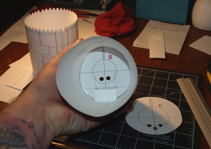 I am implementing a complete new part numbering system, at the moment this new former is "B", but that might change. While I waited for some glue to dry, and since I have the new Wheel Well in place, I decided to test build the new front Gear assembly. Following pic shows the necessary printed parts plus a little build diagram. 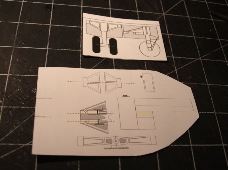 One of my goals is to create an assembly that can be fitted with no other support. in other words, I don't like the idea of wire supports sticking through little holes... so my new assembly mounts on a wide front brace and a rear support (sort of a tripod effect). Heres the assembly with some Mustang P-51 wheels I pulled off another model. The actual C-130 wheels will be a little shorter and fatter. 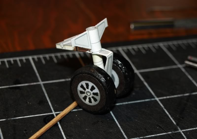 ...all looks okay and the fit in the wheel well is as intended. I'm gonna make a few small adjustments to the design but its pretty much what I had in mind. Only real question is the overall ride height of the plane. I've done a lot of measurements to try to get front and main gear to the correct height and to get the fusleage to sit at the proper angle and ride height, but I won't know for sure until I get all the gear in place. 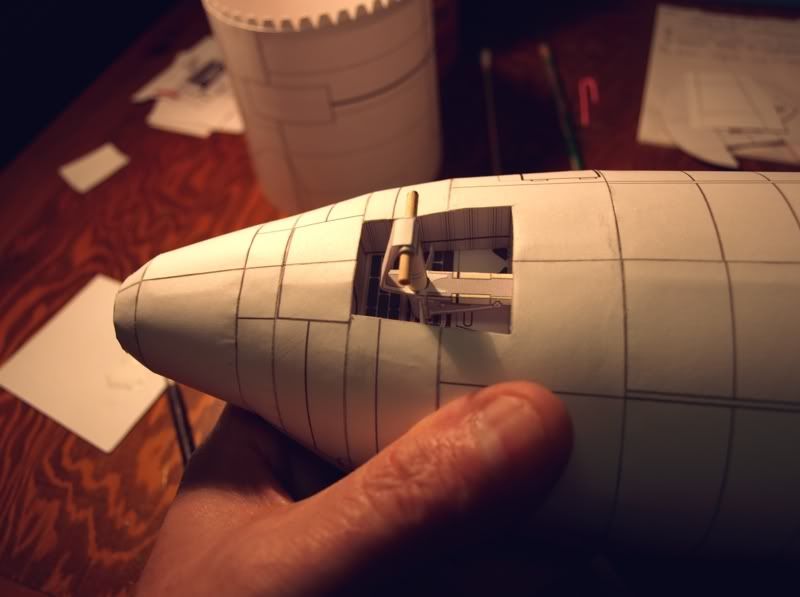 All thats left is to add three more sections of fuselage... which brings mean to the rear door/tail sections. I'm also at the point where I am cutting out the openings for the main gear wells. I remembered from my last C-130 build, that I questioned whether there should be a second former in the area of the main Gear wells. As it stands, Nobi's design has one central former where you fit the wheel well boxes.  I think two formers in that opening is the better way to allow for a flat and secure attachment of the new Gear design and Wheel Wells. So, I have doubled the applicable former "F" and added a pair of spacing braces. Its pretty simple to attach the two braces, glue them to the existing former and then drop in the second former. 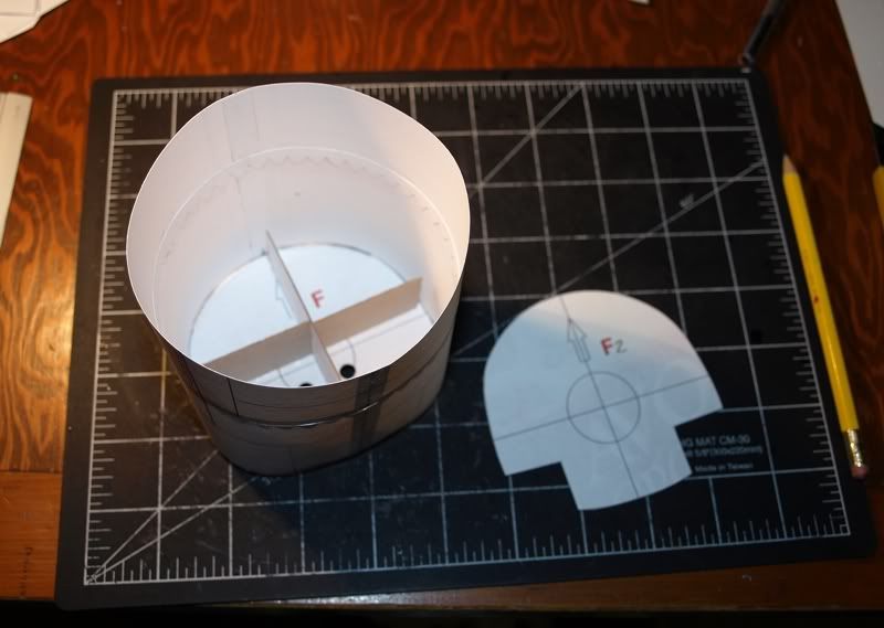 Once the openings are cut for the Main Gear wells, there are two visible former cutouts ready to receive the new wheel well boxes. The wheel well boxes now have two attachment points. Once I get the boxes printed and assembled I'll know for sure if this is all good. 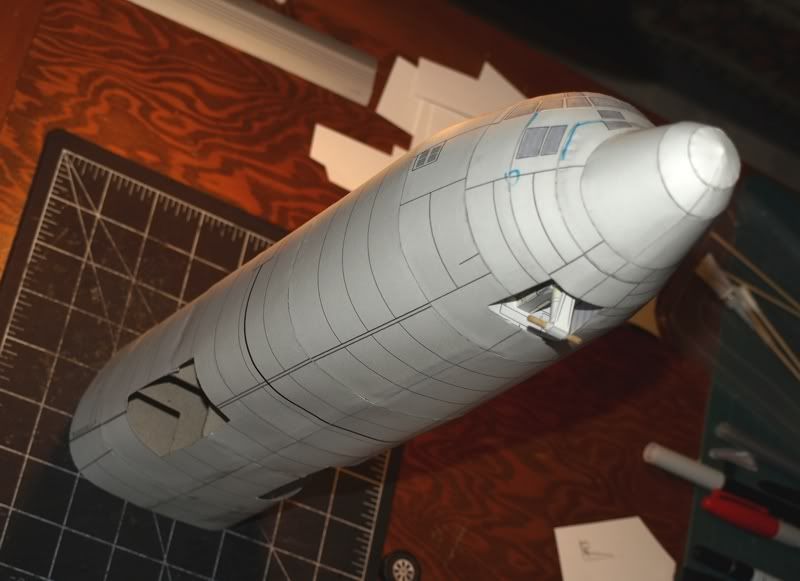 And thats it...for now... I've got a short list of tweaks and minor adjustments to deal with and then its on to designing the Tail sections. But before that, I think I will check out the fit of the side fuselage blisters. Stay tuned!
__________________
SUPPORT ME PLEASE: PaperModelShop Or, my models at ecardmodels: Dave'sCardCreations 
|
|
#32
11-22-2010, 11:13 AM
|
||||
|
||||
|
Lotta work going on here - looking good!
BTW, we usually called the "blisters" the wheel well sponsons when we didn't just call them the main gear. Neat work inside the nose wheel well - just how much detail do you want? There's a couple of electronic components in there and a window on the aft bulkhead (so you can crawl down after takeoff, look inside, and see that you forgot to pull the gear pin when the nose gear refuses to retract ...). I'll see if I still have a -1 laying around; tons of diagrams and specs in there. Yogi
|
|
#33
11-22-2010, 12:23 PM
|
||||
|
||||
|
Quote:
"sponsons" ? excellent...thats what I will try to call them! only reason I started calling them "blisters" was because I think I used to call them "bulges" and then another modeler referred to them as "blisters"...and that sounded much better! lol I used a couple of C-130 photos for reference when designing the new gear and detailing the wheel well. But I do admit...its not technically accurate, I always take a lot of artistic license to suit the model building method. And in this case because the gear and wheel wells are so well hidden, I figured I could let the technical accuracy slide a lot. Please don't let that stop you (or anyone) from sending me or posting photos and data. Its all a wonderful learning experience for me!
__________________
SUPPORT ME PLEASE: PaperModelShop Or, my models at ecardmodels: Dave'sCardCreations
|
|
#34
11-22-2010, 12:42 PM
|
||||
|
||||
|
Not sure you're familiar with this site, AirDave, but there is some interesting material on the Herc here.
C130 Pilot Gouge Downloads - Study Guides & Notes
__________________
Ashrunner "If you don't know what a lahar is, don't get in its way!" My Designs -- My Photography
|
|
#35
11-22-2010, 01:38 PM
|
||||
|
||||
|
Quote:
__________________
SUPPORT ME PLEASE: PaperModelShop Or, my models at ecardmodels: Dave'sCardCreations
|
| Google Adsense |
|
#36
11-24-2010, 08:08 AM
|
||||
|
||||
|
getting a little sidetracked with details now! lol...
tweaked the front Gear support and decided to print out the new parts and check everything. All is good... and then I got curious about the Gear door, and how it will attach. So I designed a bracket setup and tested it. yes, it does hang down a little too low in this picture...I have already adjusted the position of the brackets and door (in the kit). 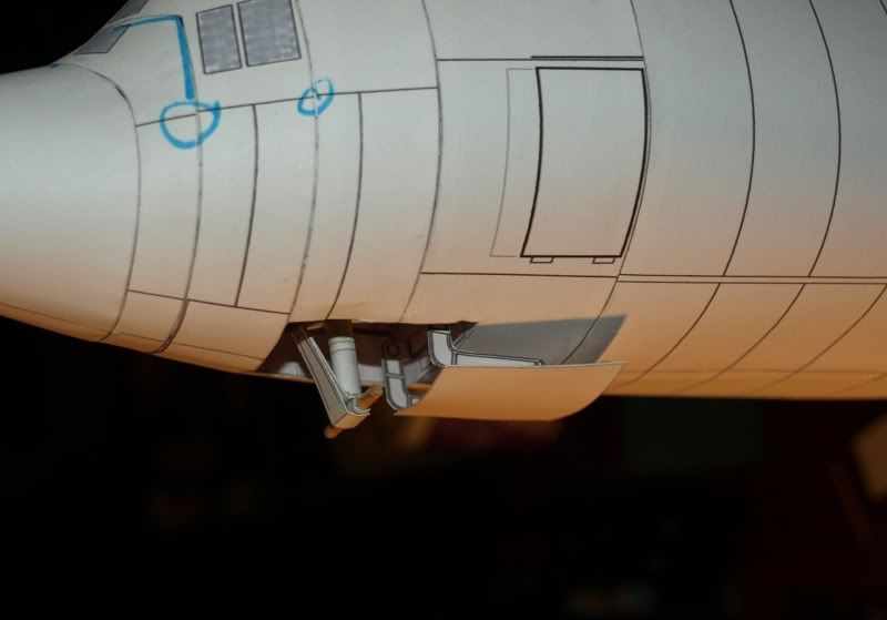 only thing I have to check now is the position of the front wheels. I notice in a couple of C-130 photos, that the front wheels sit a little further ahead than I have them. I may have to adjust the gear support to move them forward. Once I make up some wheels, I can check the clearance. .............................. and...before I move on to the Tail and aft sections of the fuselage, I figured it was a good idea to check out the fit of the new Main Gear Wells. And then I can sort out the "sponson" assembly. so, heres the new main gear assemblies... I know its not technically accurate, but I think its a vast improvement. I am trying to strike a balance between more accurate detail and build simplicity. And once it gets hidden up inside the wheel wells, behind the doors and the wheels...you won't be able to see much anyway! lol 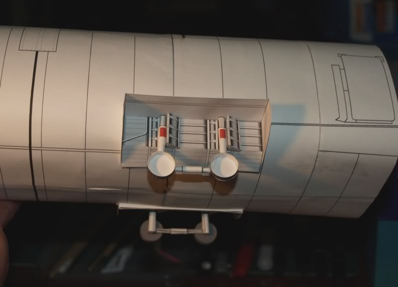 Obviously no Wheels/Tires in place yet, all you can see is the open brake drums. But I have got the wheels spaced out properly now (I think) I have deliberately left the main supports a little tall. Once I get all wheels/tires made and installed, I can check the actual ride height and angle of the fuselage and then shorten the main supports to the desired length. So...next is to attach the sponson assembly over all this. Hopefully all goes well. 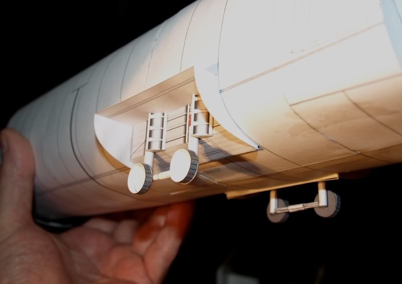
__________________
SUPPORT ME PLEASE: PaperModelShop Or, my models at ecardmodels: Dave'sCardCreations
|
|
#37
11-24-2010, 11:53 AM
|
||||
|
||||
|
Nice interpretation. Don't recall a link between the fore-aft main gear struts. Other than that looks nice - BTW the brakes are a stack of disks, but your depiction works for that as well.
Yogi
|
|
#39
11-24-2010, 02:05 PM
|
||||
|
||||
|
I saw what I thought were Brake drums in one photo.
Thanks Yogi, for telling me that they are Discs. I can simply alter the detail lines to resemble discs instead of drums. I assume the link between the two upright Cylinders is to connect and stabilize the two units? A lack of reference photos (of the main landing gear) was a problem. Thats the big reason for some modeling and artistic interpretation. Then I found a diecast model part, for the landing gear, and it answered some of the visual questions.
__________________
SUPPORT ME PLEASE: PaperModelShop Or, my models at ecardmodels: Dave'sCardCreations
|
|
#40
11-24-2010, 05:26 PM
|
||||
|
||||
|
I really like how you're redesigning the wheelwells and landing gear! Your new former looks real good, too. This model will be even better when you're all done.
Kurt
|
| Google Adsense |
 |
|
|


 Linear Mode

