


|
|
|
#181
 07-23-2016, 02:49 PM
|
||||
|
||||
|
This was EXACTLY my point...alternate ideas for how you like to create these thin tubes.
And maybe I would see something that would work in a kit. Obviously your method Nando, does not! ...lol doesn't help me at all. lol ...but still, exactly what I wanted to see. ... It did make me think though. This would be a good way to form railings for ship models. For larger tubes (2mm, 3mm) this would be a very good way to create engine exhaust pipes on aircraft, cars, etc. Use thicker wire...the wire form would then support a wrapped, shaped exhaust pipe. If you can't get the wire out the paper tube (after the glue is dry), don't worry about it. Just leave it in.
__________________
SUPPORT ME PLEASE: PaperModelShop Or, my models at ecardmodels: Dave'sCardCreations 
|
|
#182
07-23-2016, 03:29 PM
|
|||
|
|||
|
Man oh man, after seeing what all goes into the designing and building the prototype, I'm so glad we have someone like Dave to do this.
Thanks Dave for all your work, and of course, once this bad boy is released I'll be buying it for sure. It is going to be for sale at some point, correct?
|
|
#183
07-23-2016, 04:19 PM
|
||||
|
||||
|
Quote:
 As you mentioned early on there are various brackets and of course the suspension stations which are firmly bolted to the hull and the position of these bits can be easily defined and aligned on the hull sides. The attached non-scale diagram is mainly for the benefit of the general readership and is based on the rearmost of the 3 seperate and independent torsion assemblies on the left side (although together the 3 look like one long piece but in varying diameters of tubes and rods) 1 the rigid (but adjustable) mounting clamping the torsion rod to the hull. 2 the torsion rod which reverses direction by way of the torsion sleeve. 3 the torsion sleeve. 4 suspension assembly, bolted rigidly to the hull. 5 upper wishbone. 6 upper wishbone bearing Note that 2 passes through 6 without being attached to it in any way. 6 simply restrains 2 from bending whilst allowing it to rotate. Also 3 is rigidly attached to 5 to control the vertical movement of the suspension. In modelling this, and because the positions of 1 and 4 are defined on the hull sides, the rolled tubes for the torsion rods and return sleeves could be plugged into the fixed bits to keep the straight visual appearance. Any such tubes would need to be no more than 45mm long and those at that length would be about 4.5mm diam. The 3mm tubes would only need to be 30 to 35 mm long.
|
|
#184
07-23-2016, 05:26 PM
|
||||
|
||||
|
Not to sound ignorant...but I had to look up Edward de Bono. lol
... I've had to simplify a number of areas to help simplify the assembly and design. I'm convincing myself that the small size justifies this. The 1/16 scale size keeps screaming more detail, more complexity. LOL But I have to keep coming back to my own desire to oversimplify and keep the construction to a minimum. I like to follow the "first glance" idea with a lot of my designing. What you first think you see, is usually what works the best. At first glance, I saw a tube running the length of the vehicle. Then I saw some fattened areas along the tube, Then I saw some swiveling objects attached to this "tube". The more I research, the more I see the different and separate parts. The more I understand the Torsion bar suspension on this vehicle. (As an auto mechanic, I already have my fill of torsion bar suspension understanding. Repaired enough late 60s/70s Dodges!) As I keep reworking the parts, I try so hard not to let the real technical design overtake my original simplification ideas. And now I'm redesigning my design again...as a result of all this overthinking in the last few days. As long as I can retain that "first glance" look of the real thing, I'll be okay. The two most visible areas of the Torsion Rod assembly, are the front and rear extensions, which give you the impression of a tube running the length of the vehicle. I think I can live with this look throughout the length of the part. 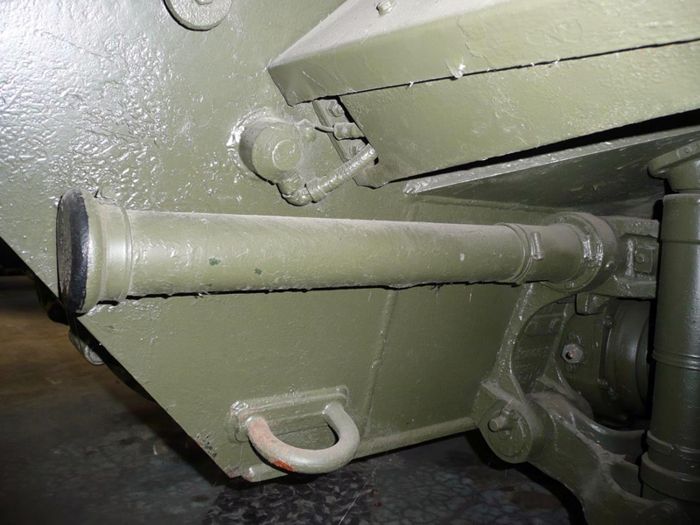 ... I like the idea of some shorter tubes...but I like the idea one longer assembly too. I'm really, as usual, shooting for the "least number of things to assemble". I can't go any larger in diameter than 3mm for any areas of the "tube". With some of the wraps and bracketry, I am pushing 5mm and more in spots. This is not only going way beyond scale sizes, but there are some spots where I just don't have the room. Part of what I changed today, has to do with the 3-5mm tube thickness and the parts/brackets that have to attach to it I've decided to cut these attachments in half. And eliminate the need for cutting precise swivel holes with very thin walls. The tube Mounting brackets can just attach to the Hull first. Then the long tube/torsion bar thingy can be attached to the brackets. The adjuster levers can attach to the front of the Tube assembly (since they don't need to actually swivel). This is all part of trying to simplify the assembly procedure too. Which I think has to be my main goal, since its always been my main design approach. ... Regardless of how this thing gets done, it is enjoyable to get this feedback!!
__________________
SUPPORT ME PLEASE: PaperModelShop Or, my models at ecardmodels: Dave'sCardCreations
|
|
#185
07-25-2016, 05:58 PM
|
||||
|
||||
|
Okay, next step is to replace those wooden "axles" with the proper paper tubes.
Normally, these tubes will be constructed at the beginning of the Hull build. (I just hadn't got around to designing them yet) And the tubes will stay in place throughout the build as part of the Hull alignment. The recommended hole sizes for the Hull (internal and external) are 5mm. Its best to leave the holes a bit small...make your axles...and then sand out the holes to fit the axles. Well, to be honest, you can roll a paper or card tube, if you want, but my recommendation in the kit will be to use a wooden dowel and wrap a paper skin around it. That way you get a straight strong axle with even dimensions. So, the paper part has four wrap sections...printed on regular weight paper...it will wrap four times around a dowel. The final result is a 5mm diameter axle...or so. You will need about a 4mm dowel. If the dowel is bigger, you can just cut off some of the paper part, and wrap less sections around the dowel. Each wrap adds about .25mm to your axle diameter. (So, 4 wraps is about 1mm) 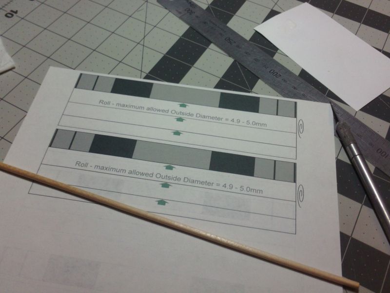 ... Dry wrap the dowel, and adjust as necessary. Sand the dowel and/or cut off the required amount of paper. When you are sure the final wrap measures aclose to 5mm, start attahcing your paper to the dowel. I glued a thin edge strip, aligning the paper with the dowel as straight as possible. Allow it to dry completely, and then start gluing about 5mm of paper, and tightly wrapping the dowel. Keep wrapping, 5-10mm at a time, making sure the wrap is staying straight. Eventually you get to the end, glue it down, and burnish it smooth. 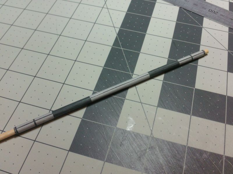 ... Use dowels that are longer thean needed...and cut off the unused ends when you are done. The paper wraps have all various bands to indicate the position of certain other parts. The axles themselves will be completely hidden from view. The paper wrap is mainly just for reference and part placement. Measure the final Axle and sand/drill out the holes in the Hull parts to accomodate. It needs to be snug, but not so tight that you can't remove the Axle. 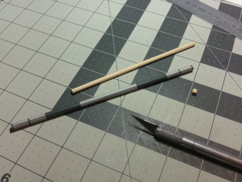 ... I've decided to follow the same wrapping approach with the side Torsion Bar Rods and Tubes assembly. I'll explain in the next post.
__________________
SUPPORT ME PLEASE: PaperModelShop Or, my models at ecardmodels: Dave'sCardCreations Last edited by airdave; 07-25-2016 at 06:19 PM.
|
| Google Adsense |
|
#186
07-25-2016, 06:18 PM
|
||||
|
||||
|
Jumping back ahead, to the Suspension stuff...
after much discussion and deliberation...and hair pulling... I have decided to leave it up to the builder. LOL But with my recomendation. I am going to include a simple part wrap for those side Torsion Rods/Tubes. The entire assembly will be in two parts with a simple joiner tube at the center. The wrap is a single tube wrap with some extra internal wraps. You can print this on cardstock and roll it into tubes if you have the skills. Otherwise, the recommendation will be to print the part on regular weight papers and wrap the part around a wooden dowel. The part has some extra wrap sections (4 in all) just like the Axle tubes mentioned earlier. The final tube must be 3mm in diameter...so if you wrap the entire part around a dowel, you will need a 2mm dowel. Just like the Axles, you can wrap less sections if you are using a larger diameter dowel. ... In my arsenal of wooden dowels, I have two packets of Wood Craft Dowels listed as 1.5mm diameter. I remember buying these because 1.5mm diameter is pretty small...smaller than Toothpicks. And, as you can see, a whole pack was only .99cents. And they're almost 8" long...which is perfect for this part.  ... Another reason they are perfect for this part, is because they are not 1.5mm diameter! They actually measure at 2.16mm or thereabouts. It pays to check things carefully.  ... So, a little sanding will bring them down a little closer to 2mm...and smooth out the rough spots. Lets start wrapping!  ... Once again, I glue a thin narrow edge to the dowel, aligning it with the dowel (straight). This is crucial, to keep the wrap going straight around the dowel. Once the edge has dried and is secure, I will start wrapping and gluing narrow sections until the entire dowel is wrapped in paper. The four sections should wrap the dowel up to 3mm...and I have added a couple of extra millimetres for overlap at the end. There are two tubes to roll, each slightly different in pattern and length. I'll cut off the excess dowel once the wraps are complete. 
__________________
SUPPORT ME PLEASE: PaperModelShop Or, my models at ecardmodels: Dave'sCardCreations
|
|
#187
07-26-2016, 08:41 AM
|
||||
|
||||
|
Here's the completed side Torsion Bar/Rod/Tube assembly.
The enlarged bits are separate wraps added after the main tube is rolled/wrapped around a dowel. The double/taller wraps are where the the mounting brackets go (to the Hull) along with the upper Control Arms. And the lower/wider wraps are where the three Tension Adjustors will attach. You can see the "joiner" tube on the right, attaching the two Torsion Tube parts. 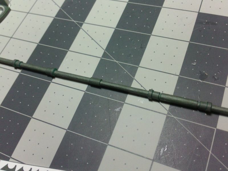 ... I like the look. And, it all fits within the size constraints. I don't have photos, but throughout the construction of these parts, I was thinking about Looker's suggestion. I started to like the idea of creating six smaller tubes representing the thinner Torsion Rods and larger supporting tubes. Shorter tubes would be easier to roll, less material to work with. So I mocked up some parts and printed some test pieces. First problem was connecting the tubes...I had to make them longer so that they overlapped a bit more. Then I had trouble making matching tubes exactly the right size so that they all fit together with the correct tightness. I had to reroll a couple of times. I realized I still had to add all the wraps and bracketry, so that hasn't changed. And the entire Tube and Rod assembly wasn't as stiff and rigid enough for my liking. I was going to try it with dowels inside for support... but that just convinced me to go back to the first plan, with two tubes wrapped onto dowels. It was a good idea...made me think...but my idea of two tubes and a joiner seems to be working quite well, so thats the route I'm taking. ... The first big change I made (to my Rod/Tube plan) was altering the Hull mounting brackets. Cutting out the very small bracket parts was challenging enough, but then cutting out 3mm holes was even tougher. The plan was to slide the brackets (onto the Torsion Tubes) and they could rotate as necessary. I would do the same with the Tension Adjustor brackets. Cutting the mounting holes was tricky and the brackets had very thin edges around the mounting holes. It took a lot of effort not to damage or tear the parts. I found I had to enlarge the parts (5-6mm diameter) to allow more material for the mounting holes. But then the parts wre getting too big. So, I decided to cut the brackets down and just attach them from one side of the Torsion Rods. I added the thinner, larger wraps and the brackets fit against them. Cutting out the brackets is a LOT simpler, even if they are small. 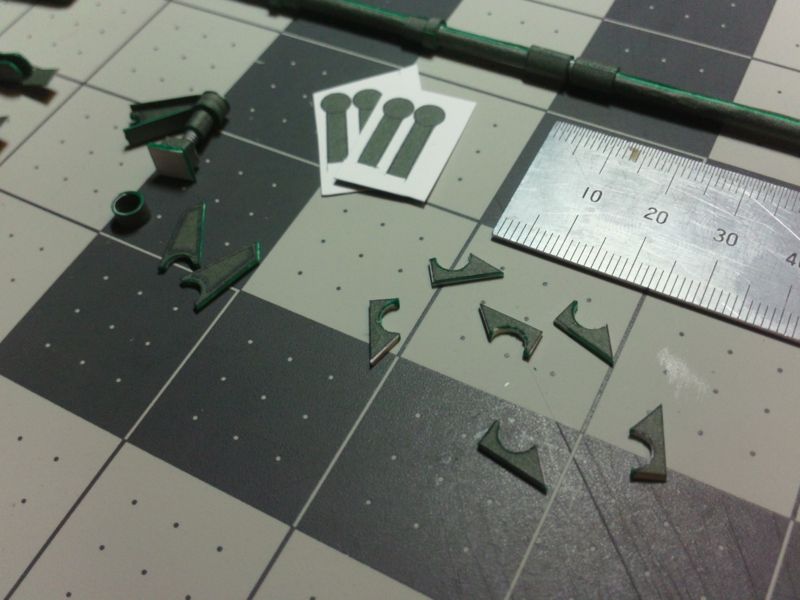 ... With the position of the bracketry marked on the Hull sides, its easy enough just to glue the half brackets into place. Five of them on either side. 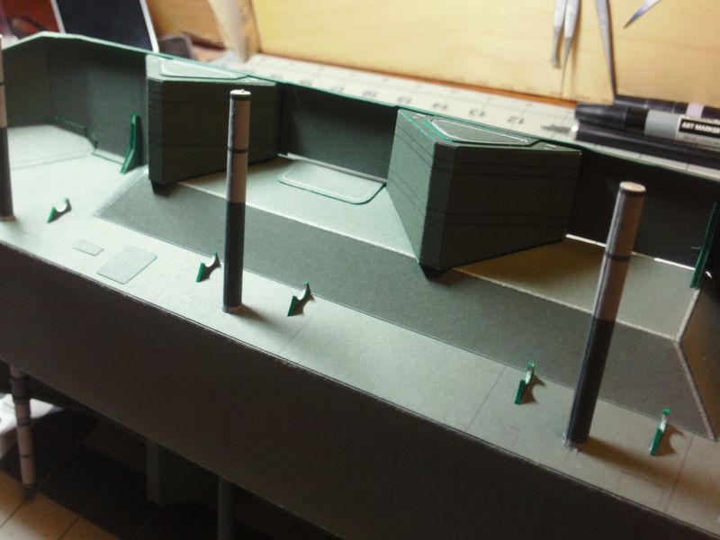 ... Then line it up and glue the Torsion Rod assembly to the brackets. It pays to check the bracket fit against the wraps on the Torsion Rod assembly. I had to sand out a few of them to get a better fit. 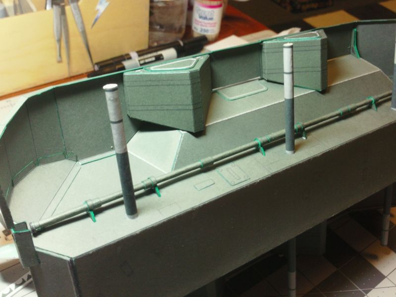 ... I also forgot to mention the end wraps on the Tube assembly. Seals up the ends of the Tubes that cover the Torsion Rods. There are small discs capping the ends of the Tubes as well. 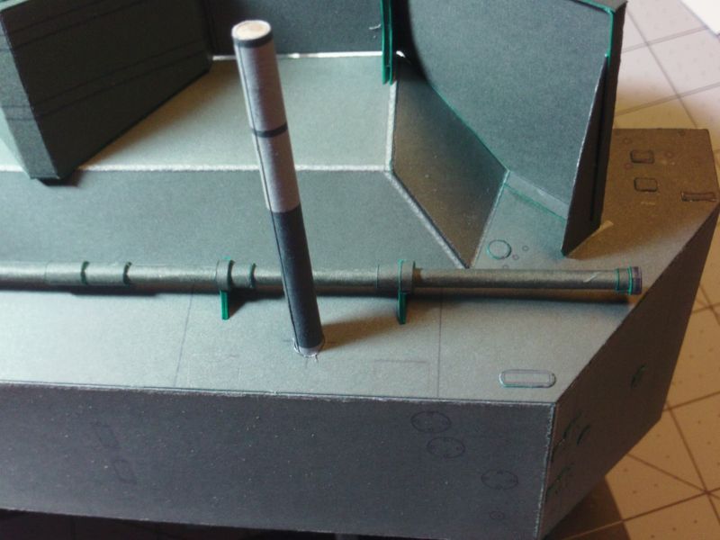 Next, I tackle the Tension Adjustors..lots of very small parts!!
__________________
SUPPORT ME PLEASE: PaperModelShop Or, my models at ecardmodels: Dave'sCardCreations
|
|
#189
07-26-2016, 10:32 AM
|
||||
|
||||
|
It looks even better completed!
I did the same thing with the Tension Adjusters... eliminated the need for cutting out a hole in the brackets. I cut off the back end of the bracket...it now just fits against the Torsion Rods. The tensioner is quite small. 1/16 is not that big sometimes! It is complicated in that it has many parts...seven in all...with some of those requiring two sides, double layer, or laminating to 1mm thickness. But its a fairly straightforward assembly needing no special skill. Tweezers and magnifying glasses come in handy though. You have to assemble three adjusters, with their base plates, for each side of the vehicle. 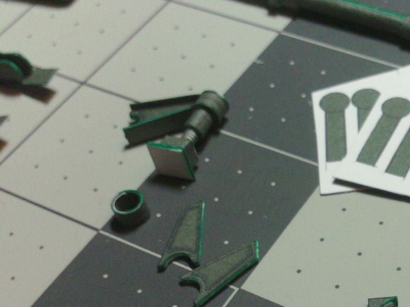 ... Install the Adusters by aligning them with the three wide wraps on the Torsion Rods, butt the bracket arms against the wraps on the Torsion Rods, and swing the Adjuster into place against the Hull sides. Glue the base plates to the Hull plates. 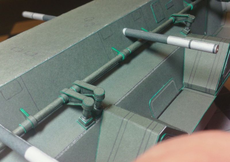 ... It really completes the Torsion Tubes/Rods! 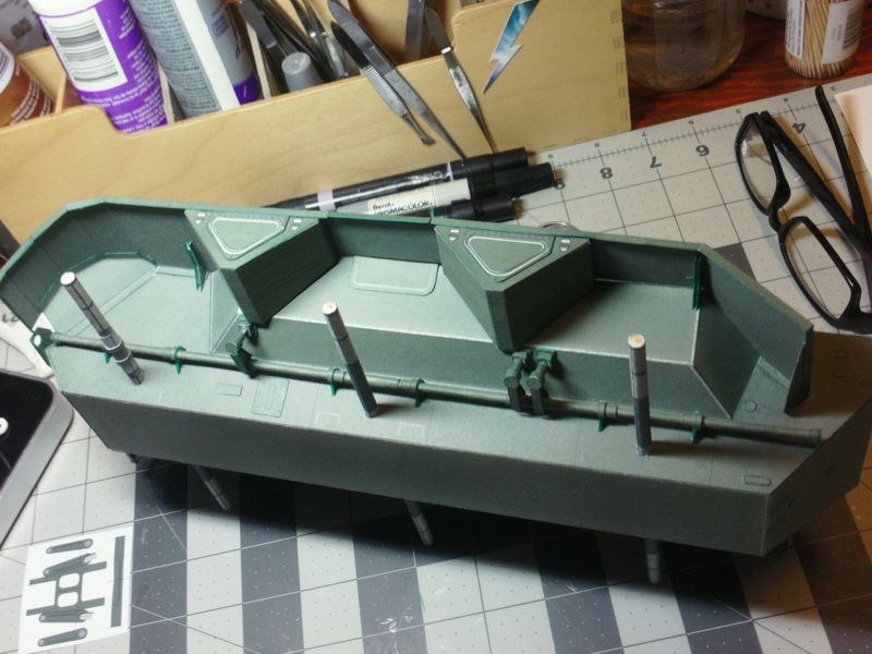
__________________
SUPPORT ME PLEASE: PaperModelShop Or, my models at ecardmodels: Dave'sCardCreations
|
|
#190
08-02-2016, 07:43 AM
|
||||
|
||||
|
Catching up...
I'm in the middle of assembling the Suspension parts, so for the past few days I have been cutting out lots of parts. At first, I finished my design for the Wheel attachment (axle, axle joints, Control Arms, Shock mounts, Suspension knuckles, etc) and I did a test build... then made numerous changes until I was satisifed. I have a few photos from that test build that I will mix up into a story here and I will show things as I take new photos (as the new parts progress). Following on from the last posted point, its time to wrap the axles. The axle supports already inserted in the Hull have markings on them for reference. A short section must be rolled, glued, and then slipped into place on the axle supports. This is an easy part to roll and assemble. I did mine on a matching size dowel...I wrapped and glued the part into a tube, then removed it from the dowel...ready to slip onto the axle. *In the upper right of the photo, you can see the assembled CV Joints/Boots ready to test fit. This provides mating points for the inner and outer axle jBoots (Constant Velocity Joints) and covers the only visible section of the axles.  ... The inner CV Joint (Boot) also includes the protruding housing from the Hull. It caps and seals the inner area of the axles as they exit the Hull. The inner Joints are assembled using two fine rings(hoops) that connect and attach to a Base ring creating the entire CV Joint Boot with the angled base that fits against the Hull. I wrapped a dowel with a paper strip (to the correct size) to aid in forming and gluing the Boot parts. 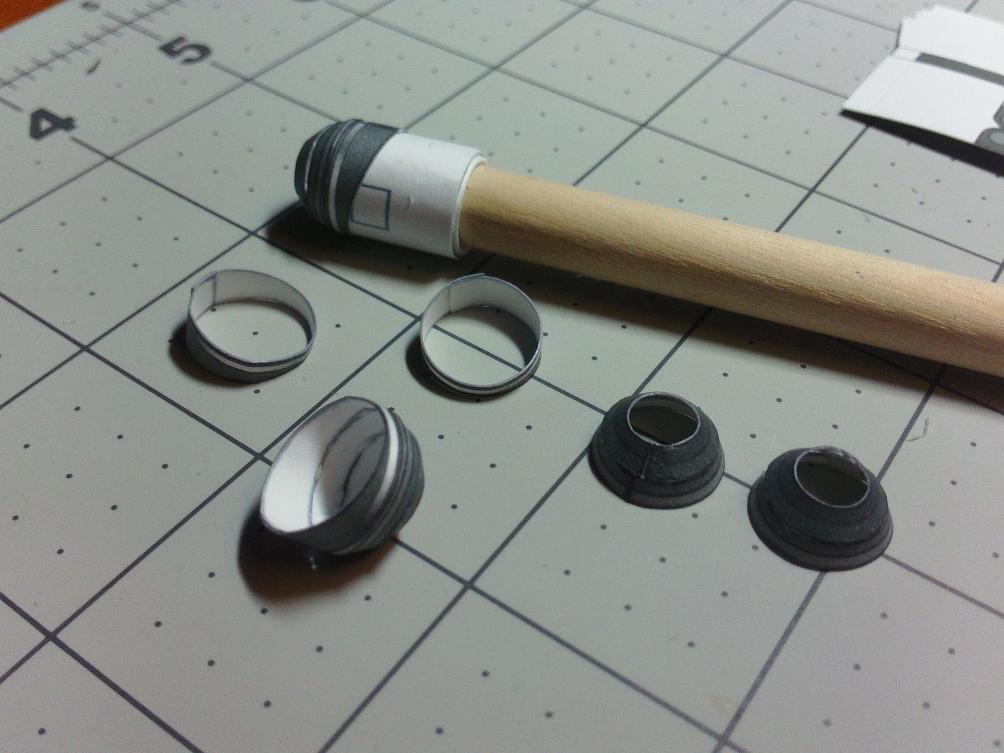 ... After the entire inner CV Joint part is assembled, I coated the insides with more craft glue for strength. Once dry, I slipped it over the axle support tube...and over the axle wraps...and lined it up against the Hull side. I edge glued it into place. 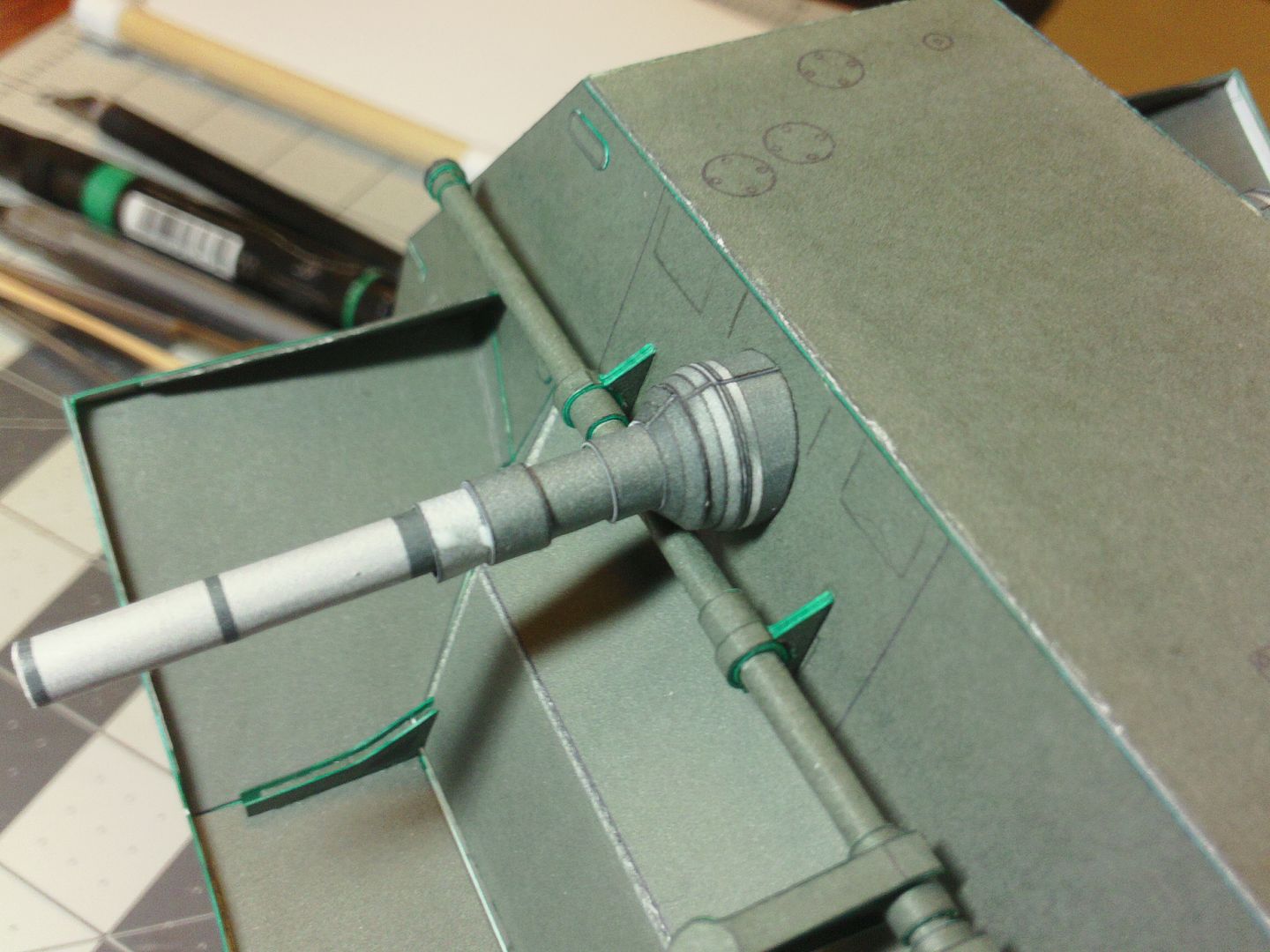 ... The outer CV Joint will connect to the larger Wheel Hub (the center of the Wheel Rim). It will be fitted last, after the suspension parts are assembled. But for now, I will prepare it. First, supporting discs have to be installed in the Hub part. The discs have to be sized to snugly fit inside the Hub tubes. They also have to fit neatly over the axle support tubes...they must slide easily onto the axle tubes, so not too tight. The two supporting discs (laminated to 1mm thickness) are installed inside the Hub. Theres a rough position suggested...and I created a simple tool for inserting the the discs into the Hubs. Just wrapped some paper around a dowel. 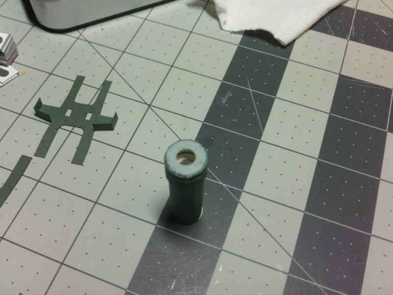 ... First support Disc goes in quite deep...the second, not so deep. I swiped glued around the inside of the Hub, and inserted the disc, making sure it stayed level. Its important to make sure glue dries before moving on with many of these assemblies. 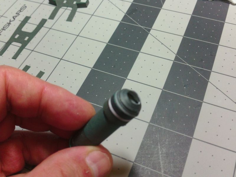 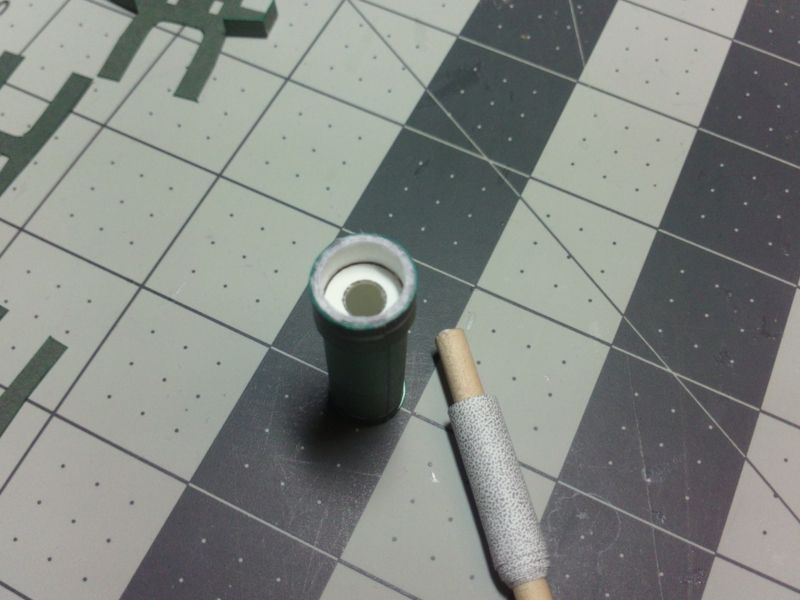 ... Then, theres a third disc...which provides more axle support, but is mainly a mounting "cap" for the CV Joint.  ... Now, add the outer CV Joint (Boot). It Glues flat to the "cap" on the Hub. The Boot is assembled the same as the inner Boot....two rings make up the rounded rubber Boot shape and a third hoop part is the Joint housing. As I said, the Hubs with CV Joints attached will be installed much later. 
__________________
SUPPORT ME PLEASE: PaperModelShop Or, my models at ecardmodels: Dave'sCardCreations
|
| Google Adsense |
 |
| Tags |
| saladin, armoured, car, project, centurion, scale, started, model, matchbox, 1/16, dinky, design, work, toys, tank, issue, basic, kit, profile, army, number, issued, remember, printing, reference |
|
|


 Linear Mode

