


|
|
|
#101
 06-14-2016, 05:50 PM
|
||||
|
||||
|
The real question isn't the "flat track" as one childhood friend used to call them, the real question is why is the Daimler Dingo doing the obstinate act and facing the other way.
Some kind of secret message to Beetles fans? And if I remember right, there were M3 halftrack versions built specifically for Lend-Lease to UK and USSR.
__________________
Screw the rivets, I'm building for atmosphere, not detail. later, F Scott W Last edited by southwestforests; 06-14-2016 at 06:05 PM. 
|
|
#102
06-14-2016, 07:01 PM
|
||||
|
||||
|
Nah, reckon yer wrong NWF. Judging by the other vehicles this is a 50's or 60's set and that's a mk1 Ferret not a Dingo. The venerable Scammell Wreckers were still in use right into the 80's, but the M3 surely died out before the 40's were over.
... and (unless it was a VW reference) only an American could refer to the Fab Four as the Beetles. It's spelt Beatles mate. ") 
__________________
Keep on snippin' ... Johnny
|
|
#103
06-14-2016, 08:24 PM
|
||||
|
||||
|
Well, they were originally "The Silver Beetles".
That was their touring name during their Hamburg period. But being a Brit myself, I would never mispell the Beatles name! ... Yes, Lesney No.61 was a Ferret Scout car. First produced in 1959. The Scammell Truck also first introduced in 1959, but that M3 was a 1958 issue! Shows how the 'murican stuff had such importance, even in Britain.
__________________
SUPPORT ME PLEASE: PaperModelShop Or, my models at ecardmodels: Dave'sCardCreations
|
|
#104
06-17-2016, 01:49 PM
|
||||
|
||||
|
So, lets run through the basic construction of the Engine covers.
I have changed the design a few times, and the photos are mixed from varied attempts, but it should illustrate the basic assembly. The Covers themselves are cut out as a single part...six covers. You can separate them if you want...or score down the center to form two banks of angled covers (3 on each side). Two layers require you to cut out the top and bottom sides and glue them together. Because of the underside panel lines, I couldn't rely on a solid colour panel for the underside. I will edge colour all the parts at this point. Also note: the strips that are the overlapping parts between each cover. 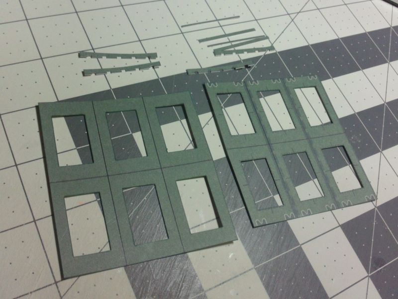 ... After I glued the top and bottoms, I will trim the edges again. Make sure all those slight overhangs are gone. And then I will edge colour all the parts for a second time. As you can see, I cut the panel in half, right and left engine covers. I also scored the lines between the engine covers. The topside are covered, but the underside panel divisions are still seen. 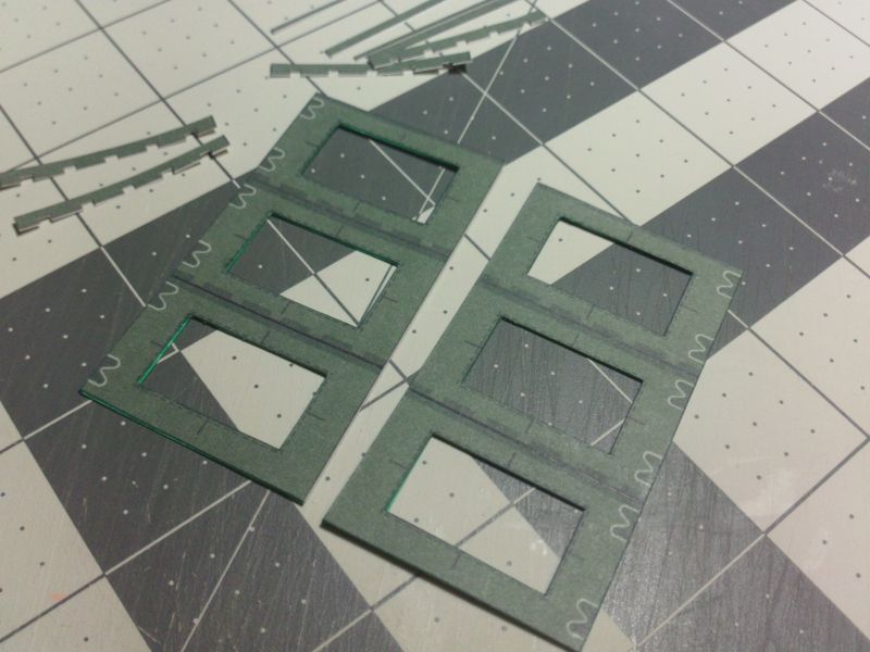 ... After all the overlap strips are attached. The notched strips glue flat to the covers. The straight strips at the end are spaced with an additonal thin strip. I have since eliminated this spacer. So all overlap strips now glue flat to the panels. 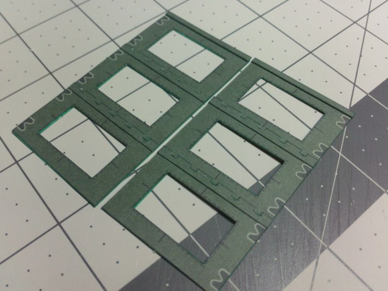 ... Here I am assembling the angled box baffles that go on each opening (on each engine cover). Two strips...scored and folded...make up each baffle assembly. The insides are visible from underneath, thats why they are coloured. I started to colour the unprinted topsides, but realized they are completely hidden underneath the Caps that go on each cover. 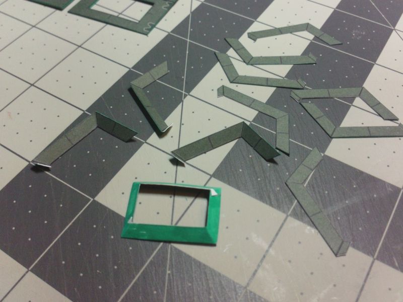 ... Here are all the parts, ready to assemble, including: the small supporting brackets for the Engine cover Caps ...and the six Caps. 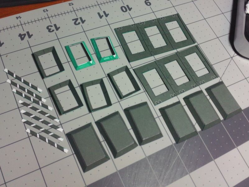
__________________
SUPPORT ME PLEASE: PaperModelShop Or, my models at ecardmodels: Dave'sCardCreations Last edited by airdave; 06-17-2016 at 02:02 PM.
|
|
#105
06-17-2016, 01:50 PM
|
||||
|
||||
|
Engine Covers continued...
The Baffle box is attached to the Cover at the center opening. I just edge glued them in place at the indicated lines. Then, cut and glue in place, the four brackets. Their positions are pre-marked. basically the center of each side. The long direction brackets are fatter than the other two, so its important to cut them right and install them correctly. 24 of these little brackets must be installed. 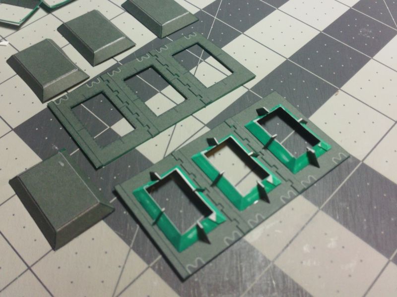 ... The little brackets extend above the edges of the baffle boxes. The Caps sit against the brackets, leaving a gap between the baffles and the caps. I just put a dab of glue on the ends of the four brackets, and centerd the caps in place. 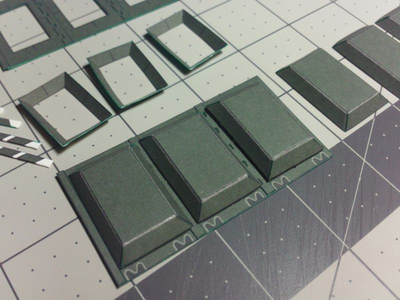 ... From the underside, you can see the gap which is how the engine covers allow air into the engine bay. At this point I realized the undersides of the caps were uncoloured and visible. I tried colouring with a green marker, but it didn't look too good. I have since added a rectangular coloured insert piece for the Caps. 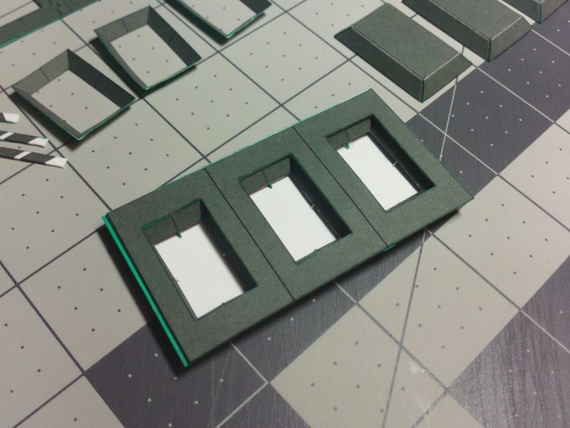 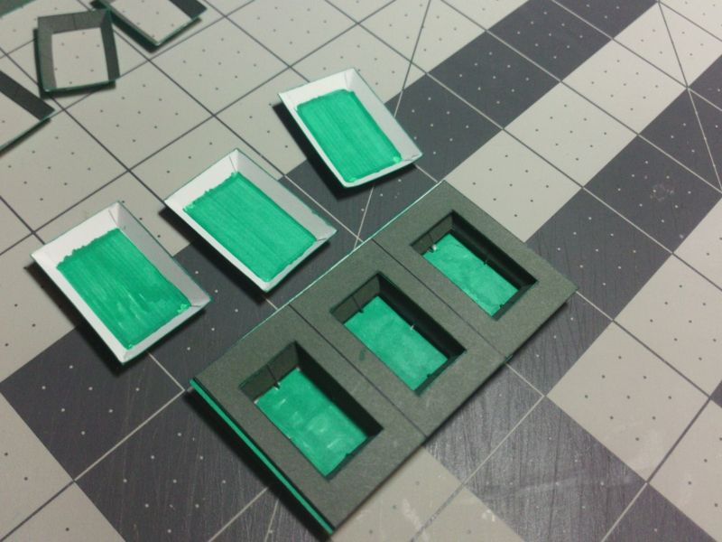 ... The Hinge design changed quite a few times...I didn't bother photographing all the early attempts. I settled on this simple hinge design...one part, rolled...with an extension to attach it to the Engine Cover. Before or after the part is rolled, it needs to be scored and folded at the base of the extension. This will be the folding "hinge". I had success with a similar idea on the Centurion model. The cardstock appears to be strong enough to survive repeated folding along a creaseline. I rolled every hinge around a 1.12mm wire (unfolded PaperClip). I was going to use the wire to align all the Hinges, but to be honest, if you glue the Hinges in place at the marked locations, they align pretty easily. 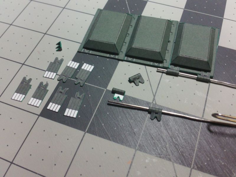 ... Glue all 12 Hinges onto the Covers, at the marked locations. Note the right and left placement of each pair of Hinges. 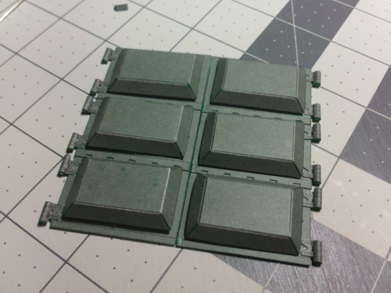 ...
__________________
SUPPORT ME PLEASE: PaperModelShop Or, my models at ecardmodels: Dave'sCardCreations Last edited by airdave; 06-17-2016 at 02:05 PM.
|
| Google Adsense |
|
#106
06-17-2016, 01:50 PM
|
||||
|
||||
|
Engine Covers continued...once more...
Attaching the hinges to the vehicle is simple.The rolled tube of each Hinge glues flat to the surface. Actually, they glue flat to small plates...not shown in these photos. I found that I had measured wrong...my little base plates were too small. So I removed the plates with the intention of printing new ones at the correct size. Unfortunately I forgot about this (a few minutes later) and I glued the Hinges directly to the Hull.! 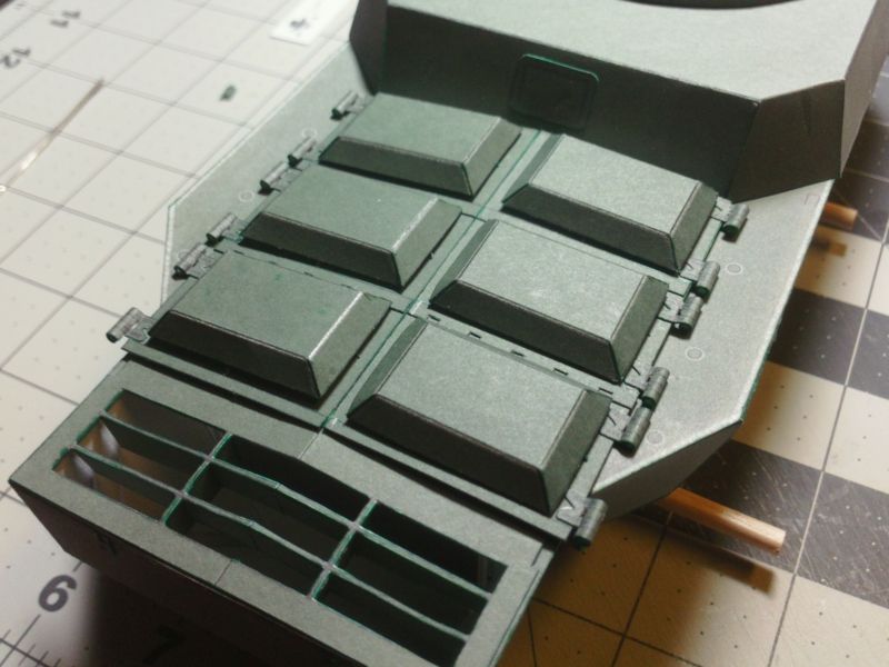 ... You can see the glue squeezing out from under one of the Hinges. For this test, I'll not worry about the plates. At least I will be able to see how well the Hinges work. But the kit will have some base plates to go under the Hinges. 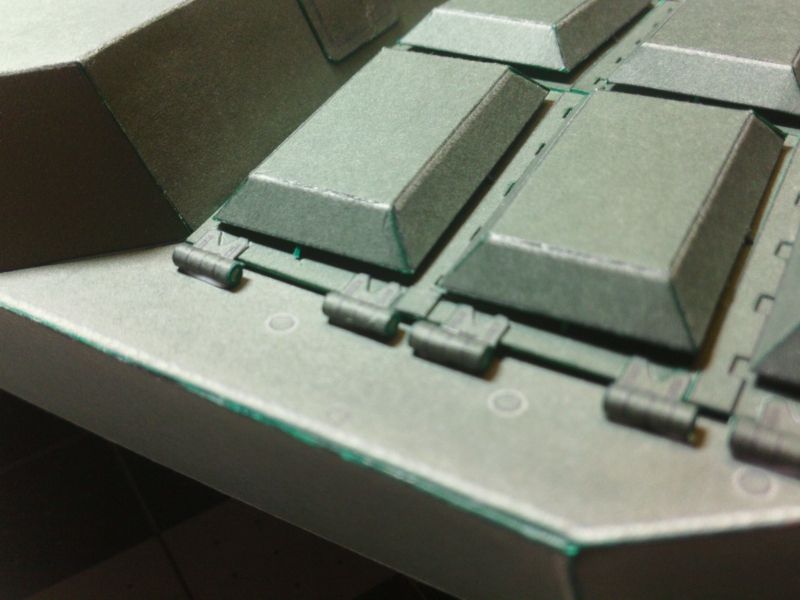 ... I still have to make the supports for the two rear Hinges that hang out past the body. Just some angle iron brackets welded to the sides of the Hull. but the Hinges seem to work really well, although the paper has to relax with time. Right now, the Hinges and hatches want to stay shut! Moving on... 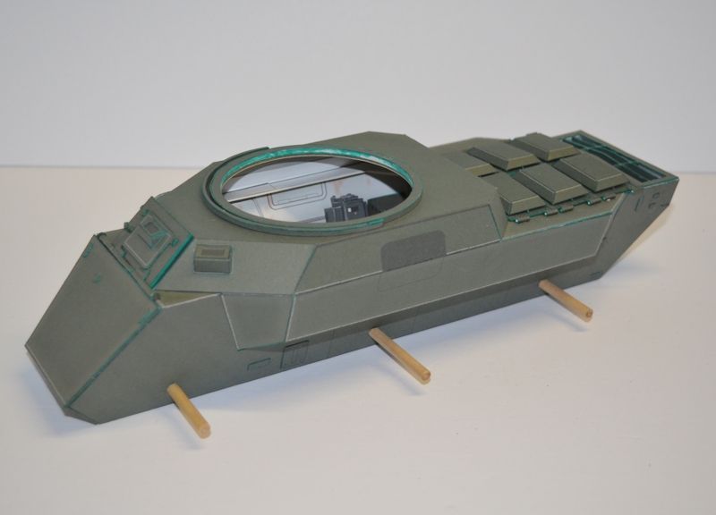 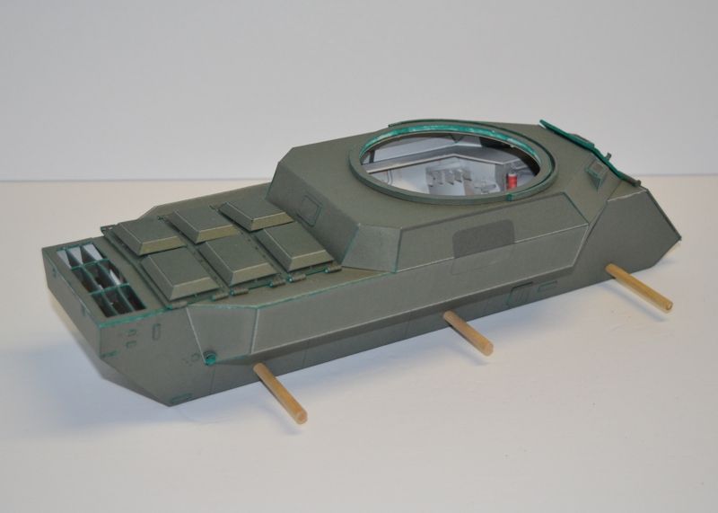 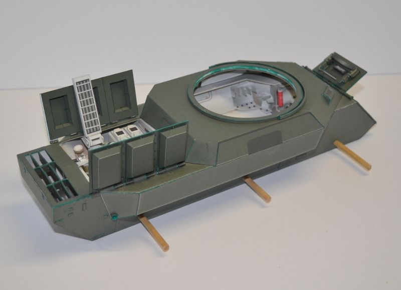
__________________
SUPPORT ME PLEASE: PaperModelShop Or, my models at ecardmodels: Dave'sCardCreations
|
|
#107
06-17-2016, 01:53 PM
|
||||
|
||||
|
And...a VIDEO UPDATE!! woohoo!
Watch it on YouTube for best HD quality: https://youtu.be/74lnT-KM_8c
__________________
SUPPORT ME PLEASE: PaperModelShop Or, my models at ecardmodels: Dave'sCardCreations
|
|
#108
06-17-2016, 01:55 PM
|
|||
|
|||
|
Wow, Dave. That's very impressive! Beautiful design and execution!
__________________
http://www.papermodelers.com/forum/a...ruder-gpm.html,
|
|
#109
06-17-2016, 02:04 PM
|
||||
|
||||
|
A thing of beauty. I knew you would work it out spectacularly
__________________
A fine is a tax when you do wrong. A tax is a fine when you do well.
|
 |
| Tags |
| saladin, armoured, car, project, centurion, scale, started, model, matchbox, 1/16, dinky, design, work, toys, tank, issue, basic, kit, profile, army, number, issued, remember, printing, reference |
|
|


 Linear Mode

