


|
|
|
#21
 04-15-2016, 11:28 AM
|
||||
|
||||
|
Quote:
I don't care what anyone says, stuff was much better back then. Even the crap stuff was better! I have some photos of the Saladin Interior...I wish I had more. I wish I had a nice side view interior plan or side view cutaway drawing, so I could get some size and position of things. (I have one cutaway drawing in my Profile magazine, buts a 3/4 view, so you can't judge sizes and positions.)
__________________
SUPPORT ME PLEASE: PaperModelShop Or, my models at ecardmodels: Dave'sCardCreations 
|
|
#22
04-15-2016, 04:33 PM
|
||||
|
||||
|
Way back in 1970s I had Tamiya's 1/35 scale plastic model of Saladin which had a battery motor driving the aft wheelset; it really could have used some kind of compensation on the center axles to allow the drive axle to retain contact with the round. Can't remember what paint job it got, just that it was non prototypical, probably something from WW2 8th Army.
__________________
Screw the rivets, I'm building for atmosphere, not detail. later, F Scott W
|
|
#23
04-17-2016, 02:22 PM
|
||||
|
||||
|
So, after a few tweaks, I have a modified chassis to testbuild anew.
I was going to build at half scale, to save paper and materials, but its more trouble than its worth. It also doesn't answer, acccurately, any fit issues. So, I scrapped that idea...all test builds will be at full scale! Minor measurement tweaks have been made to the longitudinal formers. The biggest changes being the addition of spacers and blocks to position and glue the bulkhead formers. The Bulkheads got a redesign in shape and dimensions...I also modified the cutout for the Drivers compartment. And, I modified the tops of the Bulkhead to locate and lock into the top deck plate. 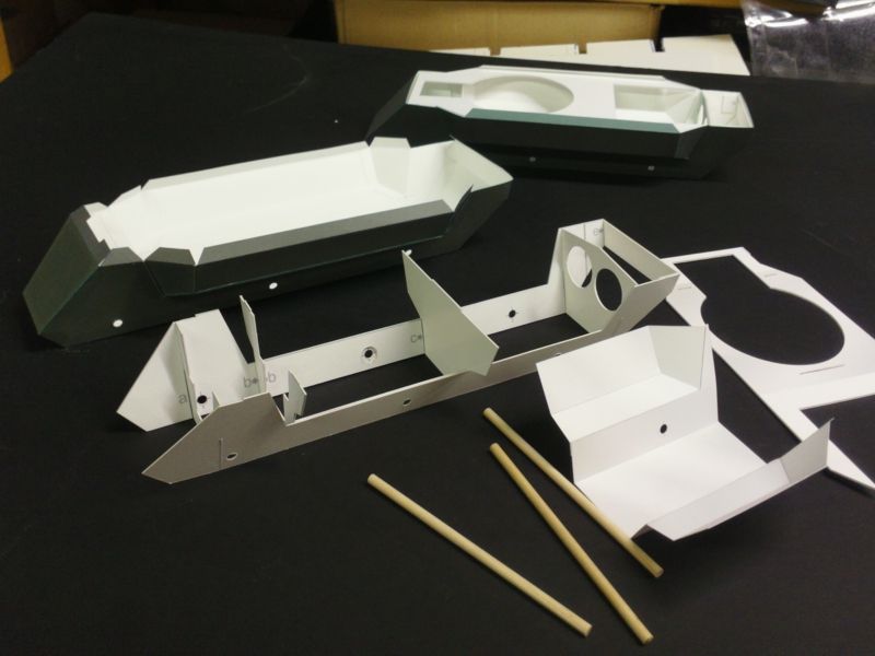 You'll also notice the first test of an interior component (the engine bay liner). I have already modified the colouring...and the next test build will include floor/wall liners for the rest of the chassis. The axles are not permanent...just testing the alignments, and using them to hold everything together. Obviously the axles are way too long. My plan was a short wooden dowel inside the suspension components for strength. 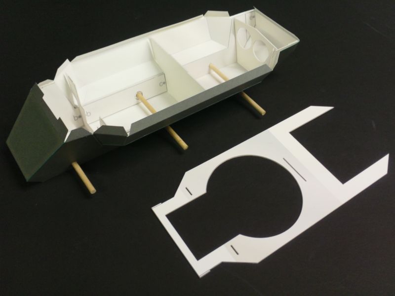 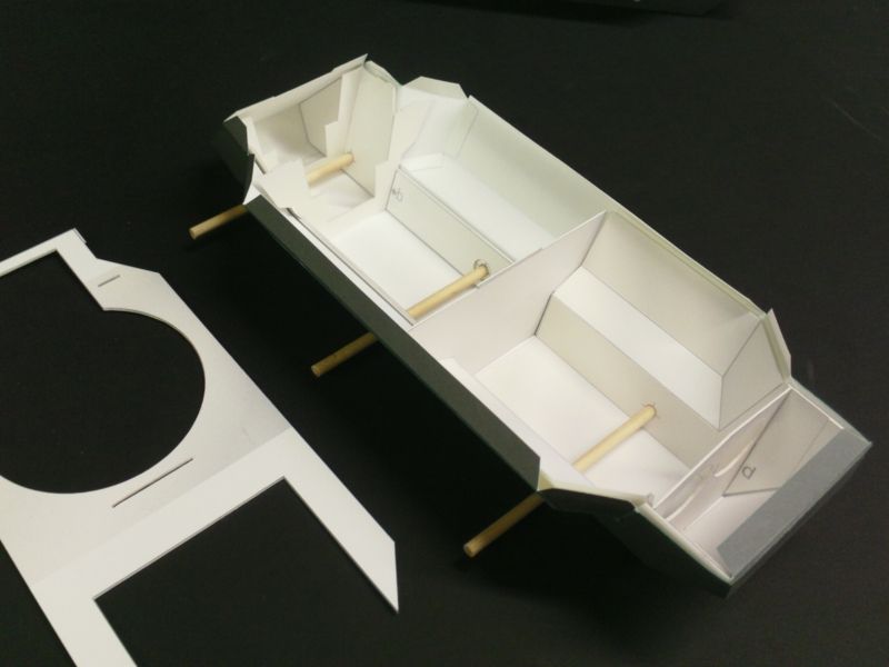 Once all the interior components are fitted into the hull, the top plate can be fitted. This plate will covered by another skin and then support the upper extension of the Hull*. *The Turret mates to the upper extension. 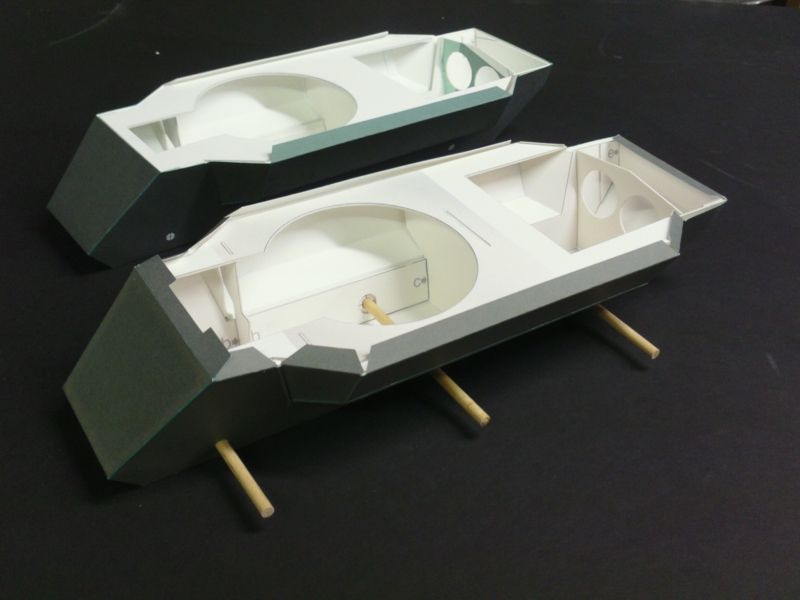 Even though there are already some corrections to this Chassis, I may build on it for a while. At least test fit the interior parts. But eventually I will build from scratch again, once I am confident of how things are going together. Stay tuned.
__________________
SUPPORT ME PLEASE: PaperModelShop Or, my models at ecardmodels: Dave'sCardCreations
|
|
#24
04-17-2016, 02:30 PM
|
||||
|
||||
|
Quote:
It would be fun to create some movable suspension. But the problems associated with that, in paper, are too much for my brain. I've already compensated for the extreme cambered stance of the Saladin by opting for a fully weighted model, sitting on vertical wheels (no camber). I could create wheels already in an offset position, but then that requires displaying the model on a suitable base. I would have to create and include a "ground" base with uneven levels, etc. Again...too much to consider right now. I think I'll stick with fixed suspension, all wheels aligned, and even ride height. But I might look at movable steering, when I get to that point. ... The Saladin doesn't have axles that traverse the vehicle, even though mine will have dowels running inside the chassis, under the floor pan. But, I am not designing the model to be a rolling chassis. Even though there are axles, I don't plan on designing the suspension, wheel hubs, etc to allow for rotating wheels.
__________________
SUPPORT ME PLEASE: PaperModelShop Or, my models at ecardmodels: Dave'sCardCreations
|
|
#25
04-17-2016, 05:06 PM
|
||||
|
||||
|
Just a suggestion Dave ... Use the three wooden axles as in your photos, but slightly elongate the round chassis holes vertically. This will allow the wheels to adopt different levels on uneven terrain. They will of course then adopt off vertical stances, unlike the real vehicle, but I could live with that. On level ground the axles will all rest at the top of the slot, so it's best to set that at a static 'norm'.
__________________
Keep on snippin' ... Johnny
|
| Google Adsense |
|
#26
04-17-2016, 05:23 PM
|
||||
|
||||
|
Resting at "the top of the slot" means maximum compression.
The model would always sit as low as possible. Without springs to push up the vehicle, the axles will always be "at the top of the slot". The dowels have nothing to do with the suspension, they are just there for strengthening. Something to build the suspension parts on top of. Making the dowels sloppy through the chassis, doesn't allow the suspension to move, if the suspension is not already movable/flexible. I don't plan on making working torsion bars and shock absorbers! The holes are actually already oval...to compensate for the angle sides in the hull! But they are not elongated. Elongated holes and moving "axles" causes another problem... I would have to raise the floor inside to clear the moving "axles". As I said, fixed suspension, fixed ride height. Just like a plastic model! LOL
__________________
SUPPORT ME PLEASE: PaperModelShop Or, my models at ecardmodels: Dave'sCardCreations
|
|
#27
04-17-2016, 05:52 PM
|
||||
|
||||
|
[Without springs to push up the vehicle, the axles will always be "at the top of the slot".]
Agreed, but only when on level ground. On uneven ground the wheels move around to compensate. ie: if the centre wheels are over a dip, they will drop into it. I've used this quite effectively for posing 4x4 vehicles on uneven ground, and just thought it might work well on a 6x6 as well. I do tend to work at much smaller scales where authentic accuracy isn't a problem though. I don't have any pics to hand, but I'm sure there's a Volker Land Rover kicking around somewhere with wobbly axles. I'll try to find one and take a pic.
__________________
Keep on snippin' ... Johnny
|
|
#28
04-17-2016, 06:02 PM
|
||||
|
||||
|
yeah, I got that.
But like you see, a wheel can only "drop" into a dip. It would rely on a three dimensional base. Like I said, I only installed dowels to provide more strength and rigidity to the chassis and to provide a point at which to build on (re: suspension components). I learned from the Centurion, that the attachment locations are the weak points for the Road Wheels, Drive gears, return rollers, etc if the Tank didn't have so many of these, it would have collapsed under its own weight. I just want to provide a stronger attachment for each suspension point. A small dowel, maybe only a few millimeters, sticking out, is just a strong attachment point. Because that dowel goes all the way through the hull, it is even stronger.
__________________
SUPPORT ME PLEASE: PaperModelShop Or, my models at ecardmodels: Dave'sCardCreations
|
|
#29
04-17-2016, 06:19 PM
|
||||
|
||||
|
OK, I yield the point. Being so visually effective on simple 4x4 models I just thought I'd throw in the idea. I've just found that Volker Landy, and it doesn't have the oval axle slots anyway. It's axles are springy plastic bristles, so there's a fair amount of spring anyway.
__________________
Keep on snippin' ... Johnny
|
|
#30
04-17-2016, 07:14 PM
|
||||
|
||||
|
I'm going to think a little more when it comes time to deal with the suspension.
It would be very cool to create some movable parts. Steering and suspension would be quite impressive. we'll talk more later.
__________________
SUPPORT ME PLEASE: PaperModelShop Or, my models at ecardmodels: Dave'sCardCreations
|
| Google Adsense |
 |
| Tags |
| saladin, armoured, car, project, centurion, scale, started, model, matchbox, 1/16, dinky, design, work, toys, tank, issue, basic, kit, profile, army, number, issued, remember, printing, reference |
|
|


 Linear Mode

