


|
|
|
#31
 04-18-2016, 06:27 AM
|
|||
|
|||
|
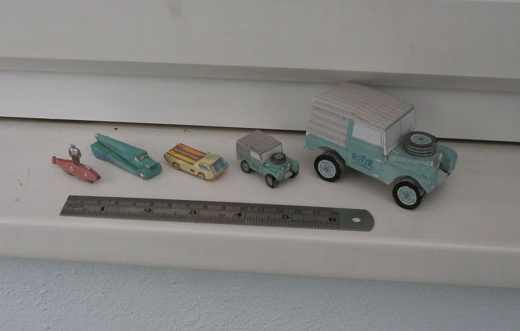
Hang in there Dave. You always find a solution that works. The Centurion tracks are a perfect example.

|
|
#32
04-18-2016, 07:16 AM
|
||||
|
||||
|
LOL
Well John! you had me stressing over this all night! I really like the idea of some movable suspension. I even like the slotted chassis idea! But first I couldn't get past the idea of Shocks that could compress along with movable Control Arms. And the fact that there are six wheels and sixteen(?) shock absorbers! And Torsion Bars!! I would have to hide springs, inside the shock absorbers? hmmm But that means introducing parts other than paper?....hmmm In the end, I can't get past the lack of room for sliding axles. With dowels as rigid axles, the wheels, and control arms and all other suspension bits, would have to move up and down (along with the axles). And thats no good! I'm just not seeing this as a working option. At least not without overdesigning the model. And I don't want to make it so complicated.
__________________
SUPPORT ME PLEASE: PaperModelShop Or, my models at ecardmodels: Dave'sCardCreations
|
|
#33
04-18-2016, 08:46 AM
|
||||
|
||||
|
Whatever your solution, Dave, I'm sure it will be elegant,, buildable, and truly reflect the original subject.
Your earlier pictures of the suspension floored me they are so complicated. You'll figure something good out for this. Your past models prove it. Joe
__________________
Currently building Heinkel Models/Ron Miller Authentic Nautilus.
|
|
#34
04-18-2016, 08:51 AM
|
||||
|
||||
|
Hee hee ... If you build things in 1:100 scale or smaller like I do, all of this detail is hidden behind the wheels ... so it usually just isn't there, or at most just drawn onto the chassis.
 I may not build in these large scale sizes, but I do enjoy watching the design processes in action. So keep on doin' what ya doin' Dave. I'll be on the side just watchin'.
__________________
Keep on snippin' ... Johnny
|
|
#35
04-18-2016, 09:19 AM
|
||||
|
||||
|
Just for an extra (Hopefully helpful) input ... Looking at the diagram in your last post, a complete wheel to wheel dowel axle could be used through the dive-shafts, to support the whole thing rigidly ... but how about using a flexible rod instead of a dowel? In my mini models I use plastic bristles from a yard broom as axles. These are strong enough to use them in Volker's 1:53 scale cars as well, instead of the usual toothpicks. In that scale it is like comparing a Dinky car to a Whiz-wheels one, and the bendy bristle simulates suspension. Not sure what sort of source you'd use to get a bendy axle in your big scale stuff though.
__________________
Keep on snippin' ... Johnny
|
| Google Adsense |
|
#36
04-18-2016, 11:13 AM
|
||||
|
||||
|
If it can't be done in paper, I can't include it in a printable model kit.
I'm not a fan of specifying the use of other materials. I provided wire diagrams for the railings on the Turrets of my PTBoat. But you can actually cut out the paper railings and use them...I did. I tolerate the use of clear plastic for canopies...I usually provide a template. But theres always a paper canopy provided! I often recommend the use of dowels and toothpicks inside paper parts for strength. The dowels I am using will be trimmed down to the necessary length. They will not be part of the model. They will be a suggestion to add strength and rigidity and provide a more secure connection between the external suspension and drive components to the Hull. Since dowels come in some specific sizes already (and can also be easily sanded to the correct size) I will include aligned markings for holes through the chassis to place those dowels. In paper I will simulate Drive Axles coming out of the Hull, connected to Suspension components. I am thinking these can be rolled/constructed, assembled, and glued to the Hull like all the other suspension parts. The larger scale might demand more parts, more details, more visually accurate assemblies, etc but moving suspension parts may be just too much for me to bother with. Lets wait until I get to the suspension. I'll design what I intended...and then see how it might be augmented or modified.
__________________
SUPPORT ME PLEASE: PaperModelShop Or, my models at ecardmodels: Dave'sCardCreations
|
|
#37
04-21-2016, 07:04 AM
|
||||
|
||||
|
Work continues creating some "liners" for the Hull.
Specifically the Engine compartment, the main Hull compartment (underneath the Turret), and the Driver's compartment. I have had to redesign these parts a few times to get them to fit. And as a result, I have tweaked the internal formers and bulkheads some more. 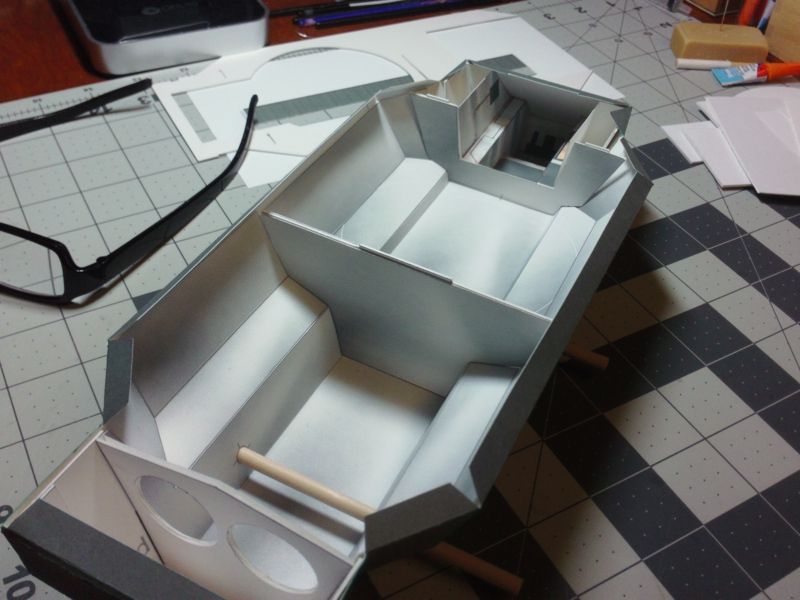 My goal is to create compartmenst that I can fit interior components into. And since the viewing access is limited, I want to keep the compartment walls as simple as possible to assemble and install. At first I was struggling to get dimensions perfect...get the parts to fit inside everything perfectly. It was a struggle...once I got one part to line up properly, another spot had issues. lol In the end, I realized it doesn't need to fit perfectly. For example, the tops of the sides of each compartment are well hidden under the top plate and glue tabs, so by shortening the sides, installation becomes much simpler. 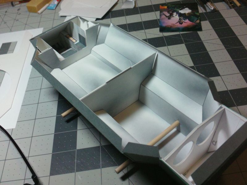 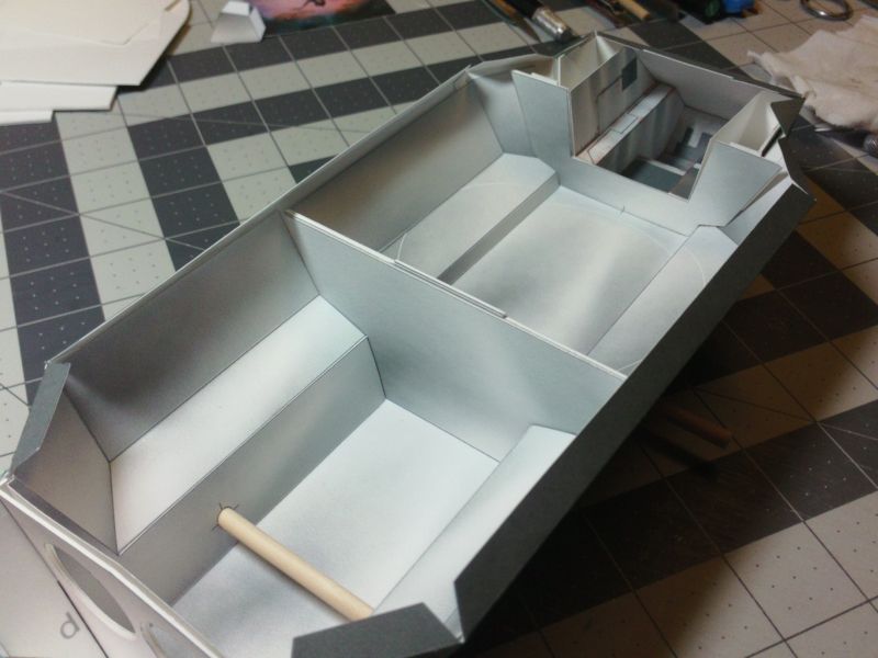 Anyway, I think I am satisfied with the compartment liners themselves, so now I move on to filling them up with interior objects. *I also started to play with colouring and other surface details (mostly in the Driver's cockpit). 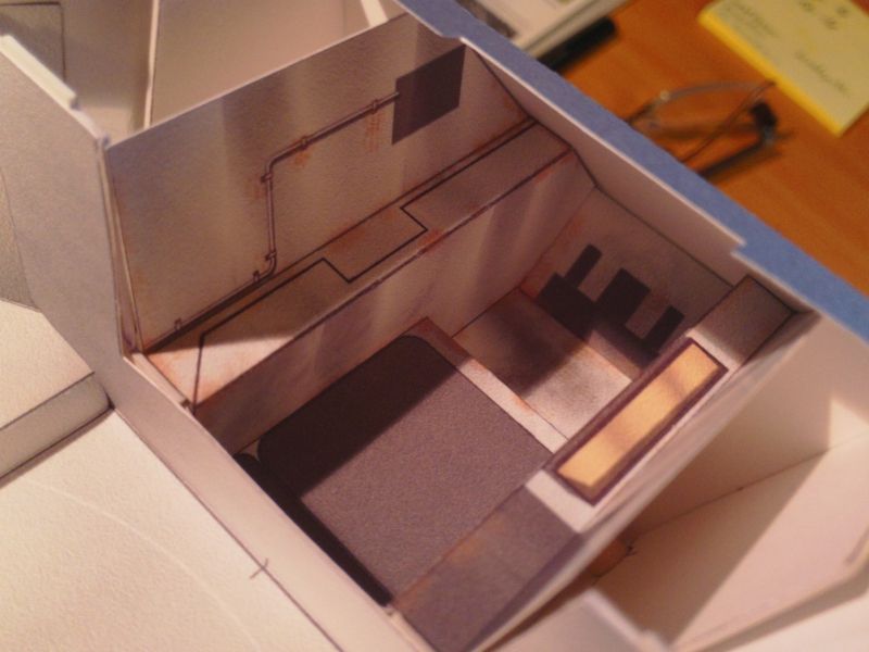
__________________
SUPPORT ME PLEASE: PaperModelShop Or, my models at ecardmodels: Dave'sCardCreations
|
|
#38
04-26-2016, 06:56 AM
|
||||
|
||||
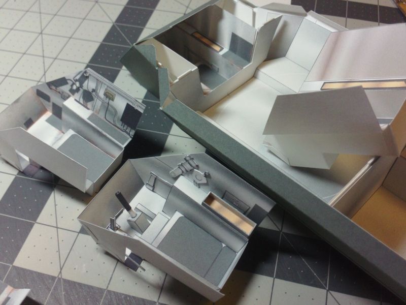 Well...thats four Cockpits built! lol Lets do five! Obviously, as the model design progresses, I keep changing the shape and fit of the cockpit tub and its related parts. I've also come up with other design ideas, so changes have to be made to suit. My first ideas were inspired by the details in the 1/25 scale Tamiya plastic model kit. This turned out to be a false and inaccurate portrayal of the interior. I have since acquired a number of actual Saladin Interior photos and I am modifying my designs based on those. I think I've hit upon something close to the final design... I'll have to build another Hull now (number three!) and test fit the cockpit to be sure. ... New tub is slightly different again. Heres all the basic bits: 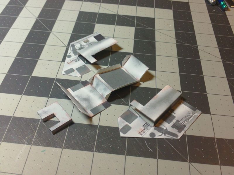 ... And most of what goes inside... you can see some of the parts I've started to assemble. Some parts require laminating to thicker card/multiple layers, to create 3D effect. The cockpit is well hidden, and the view into the driver's station will be severely limited. Some of these interior parts will not even be visible! For that reason, I am focusing on larger objects for assembly. Other details will be flat laminated parts or just surface artwork. 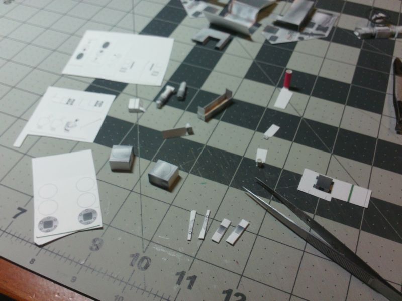 ... And here is everything, ready to assemble into a complete cockpit tub. The tub can be assembled outside the vehicle if you like, and then installed (before the Hull skins are put on). 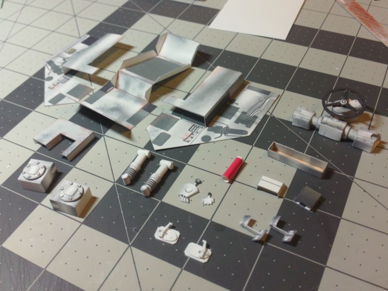 ... Steering controls are mounted slightly above the Driver and at a funny angle. Space is limited in the little cockpit! Here is my simplified rendition of the steering assembly that is mounted upside down, at the top of the tub. And, the completed tub awaiting the Steering parts...and a Driving Seat! 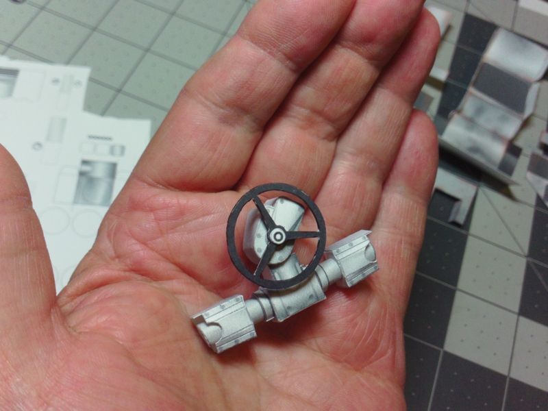 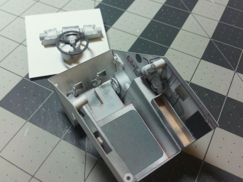 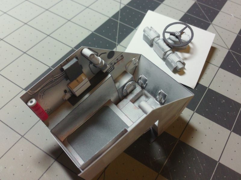 ... Once the Steering assembly and Seat are installed, the Tub is ready to fit into the Hull Former assembly. I guess, now its time to start on that fourth Hull! 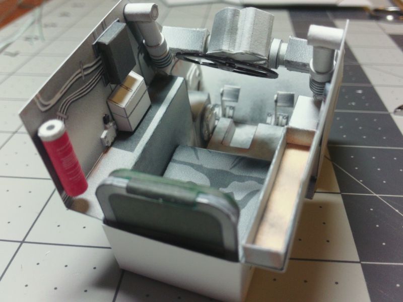 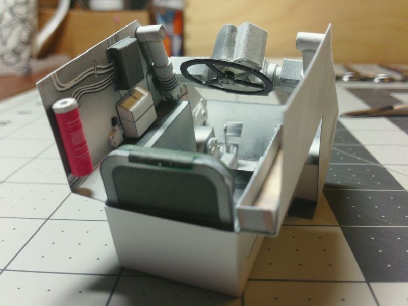
__________________
SUPPORT ME PLEASE: PaperModelShop Or, my models at ecardmodels: Dave'sCardCreations
|
|
#40
04-27-2016, 06:53 AM
|
||||
|
||||
|
So, if you have been watching my Twitter feed, you'll know that last night I assembled Chassis number three!
It was time to rebuild from scratch since I have modified the Cockpit tub a few times and I need to make sure it still fits. And, because I modified the Formers to suit the Cockpit changes. Anyway, steps are the same as mentioned earlier... two main longitudinal Formers, four Bulkhead formers and one rear cross-brace. Theres also four locating blocks that attach to the longitudinal formers. Everything lines up nice with interlocking tabs and locator blocks. Easy peesy. 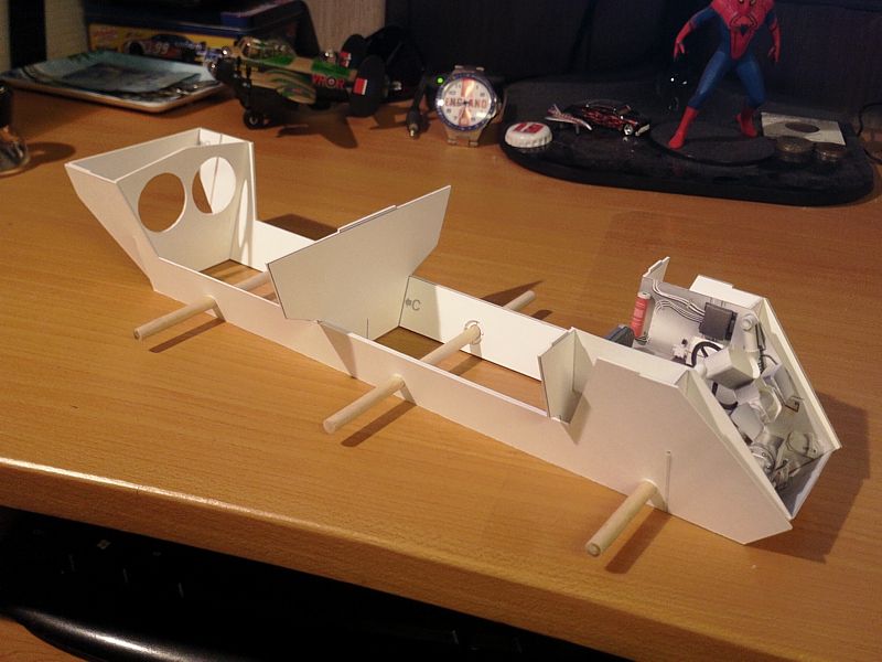 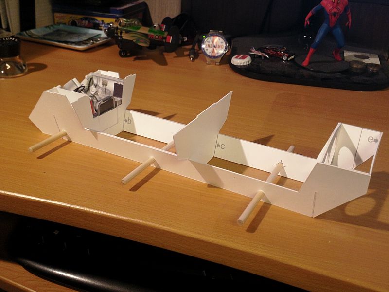 ... New Cockpit Tub assembly drops in place...and is glued in place to the two front Bulkhead formers... making sure the rear edges align flush with the second Bulkhead former. I have two minor tweaks to make in the design: tub sides are about .5mm too tall, and I need to widen the spreader that fits inside the steering mechanism (about 1mm). 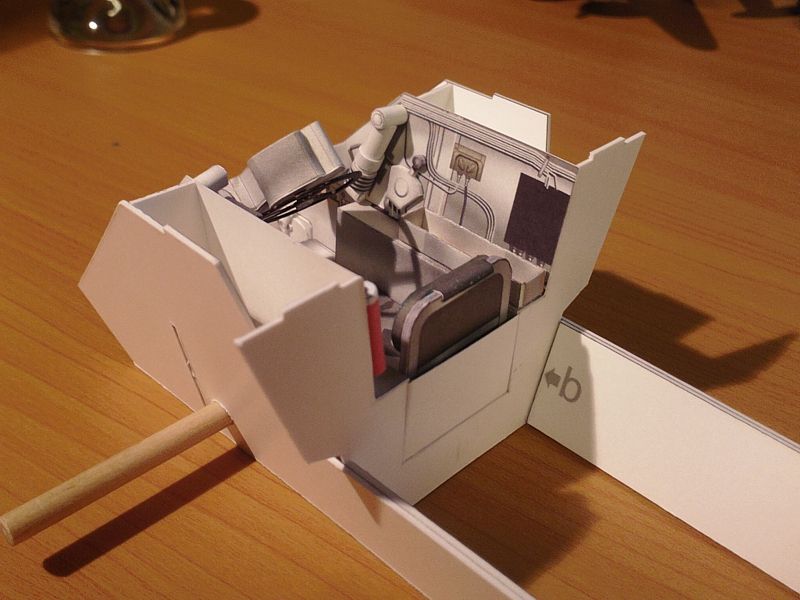 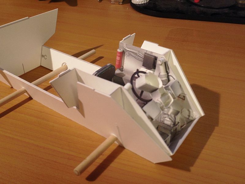 ... Next step is to finish the design work on the central (under-Turret) Interior and fit it into place. For that, I will also need the outer skins (to test the actual fit and alignment). So, much work to do before the next update. Follow on twitter for more fun. https://twitter.com/cutandfolddave
__________________
SUPPORT ME PLEASE: PaperModelShop Or, my models at ecardmodels: Dave'sCardCreations
|
| Google Adsense |
 |
| Tags |
| saladin, armoured, car, project, centurion, scale, started, model, matchbox, 1/16, dinky, design, work, toys, tank, issue, basic, kit, profile, army, number, issued, remember, printing, reference |
| Thread Tools | |
| Display Modes | |
|
|


 Linear Mode

