


|
|
|
#51
 05-13-2016, 07:38 AM
|
||||
|
||||
|
okay...so...I have been fiddling with the skin some more, and the upper deck plate
and thinking about how I will proceed with the upper Hull structure... and I finally decided to continue with my original design and see how it comes together. It all appears to be working so far. But I had to adjust the shape and fit of the printed upper deck plate before I could continue. It didn't fit correctly against the deck plate former. So...glue the deck plate former into place. It locates with tabs and against the mid bulkhead. 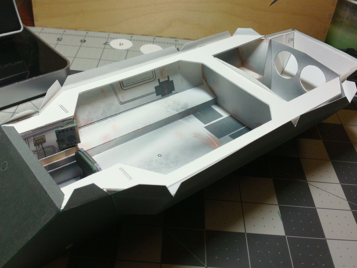 ... Then fold down (and glue) the three front tabs, and four rear tabs. The rear extensions tend to bend and move around. It is necessary to pay attention and get them positioned correctly under the tabs. 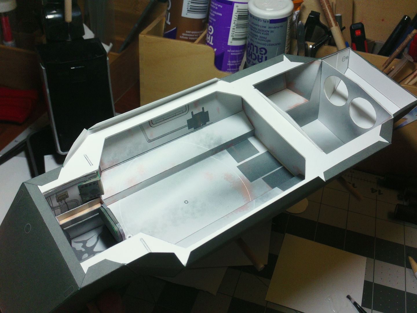 ... Then the printed top deck plate goes on. One of the major changes i made, is to split the plate into front and rear halves. The seam is hidden inside the upper Hull extension and it makes it a lot easier to get it positioned correctly. I noticed after building many sets of Hull skins, that they vary a little bit in width. I guess with all the seams and angles, its easy for it to fluctuate a bit. Being able to shift that top deck plate and get it lined up, is a help. 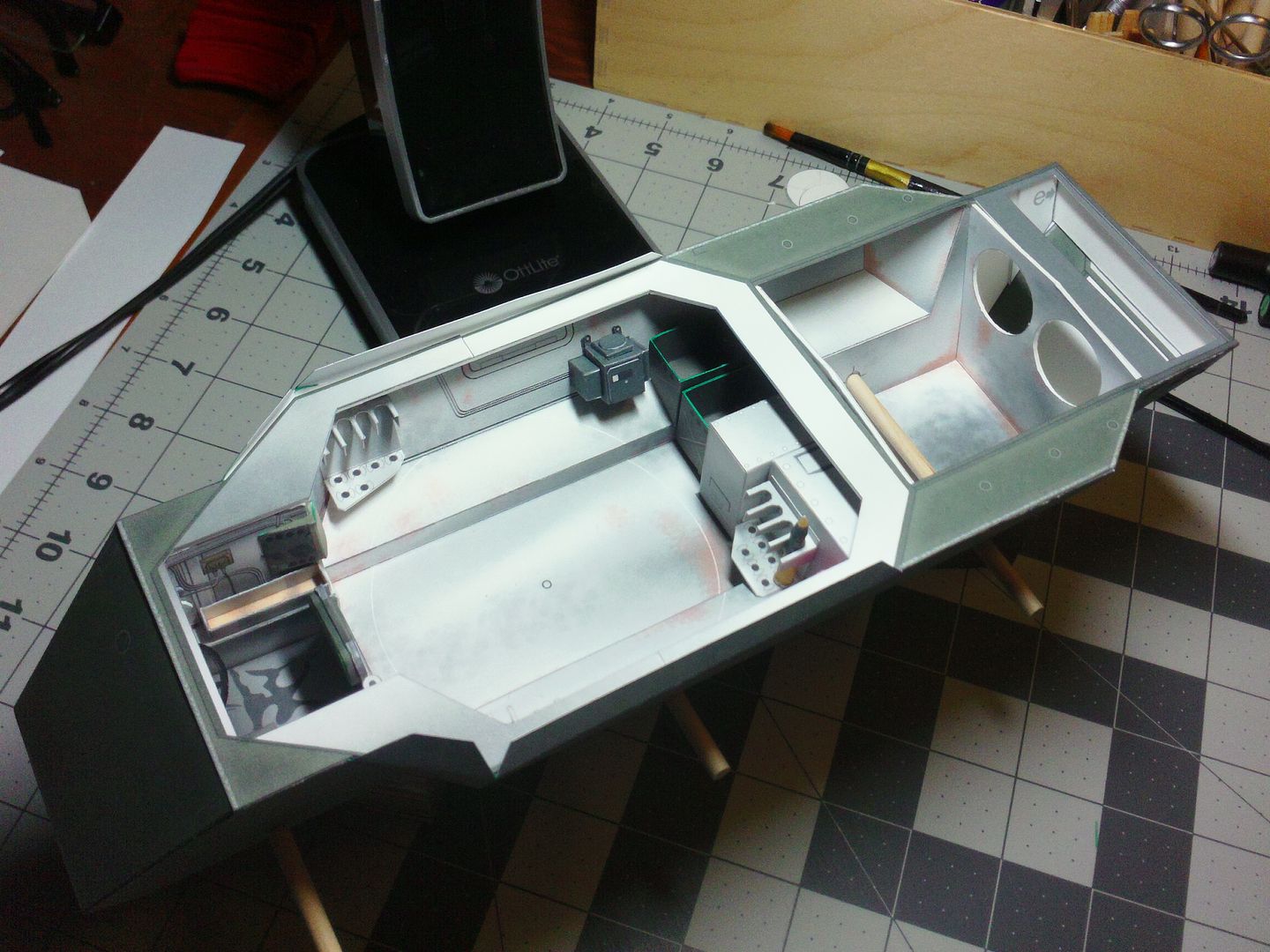 ... It appears to be fairly easy to fit all the interior components (under the Turret area). Theres plenty of access before the upper Hull goes on. I am assuming that fitting the Engine bay components will be just as easy. If not, then I will have to suggest leaving the upper deck plates (former and printed) until a later time. Hopefully I have not jumped the gun by gluing them in place now! 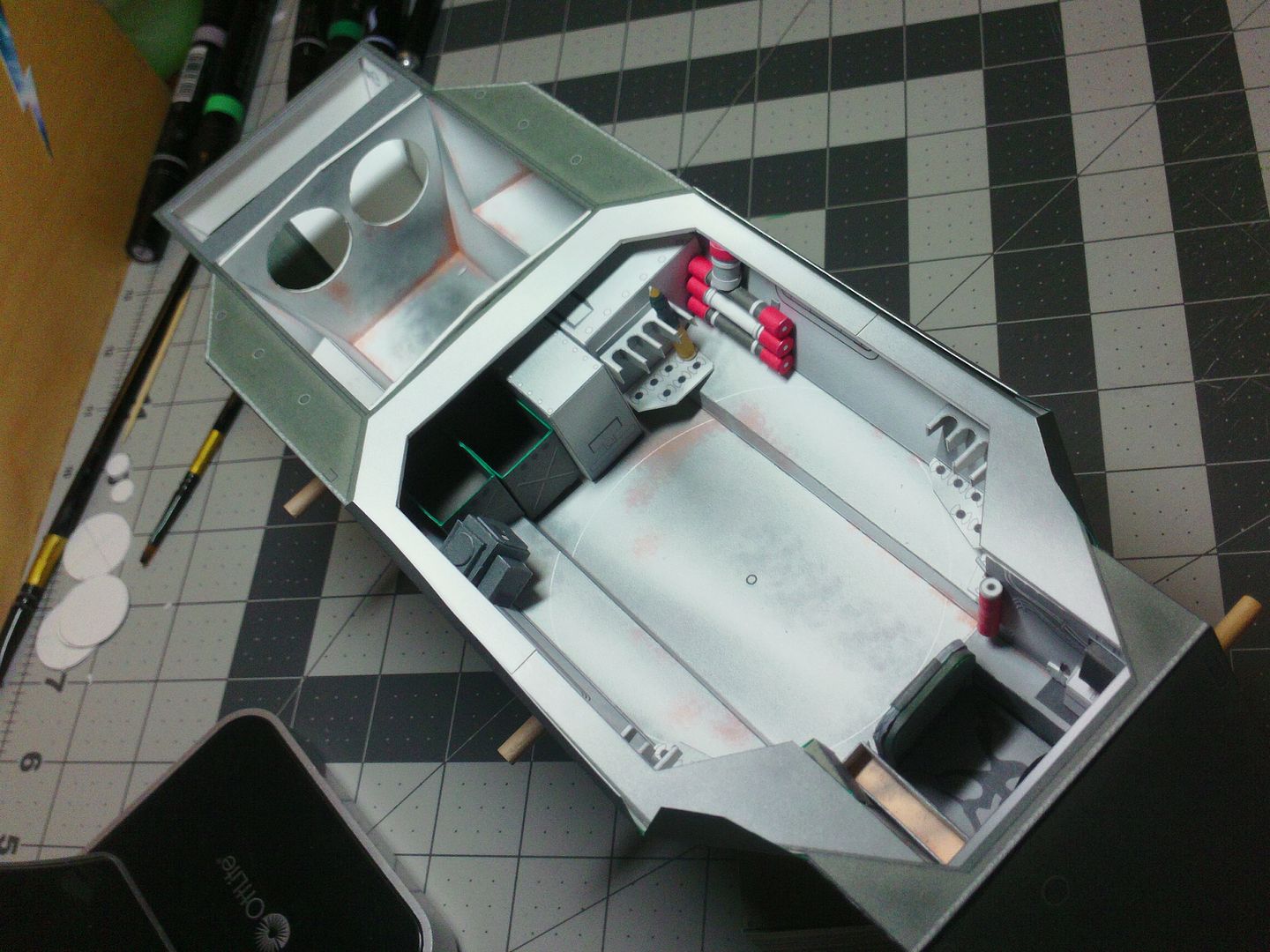
__________________
SUPPORT ME PLEASE: PaperModelShop Or, my models at ecardmodels: Dave'sCardCreations 
|
|
#52
05-13-2016, 08:40 PM
|
||||
|
||||
|
Quote:
At least for the time being.
__________________
Screw the rivets, I'm building for atmosphere, not detail. later, F Scott W
|
|
#53
05-22-2016, 10:25 PM
|
||||
|
||||
|
Holiday weekend here this weekend...Victoria Day
Nascar All Star race on Saturday night had me in front of the TV. And a bunch of stuff on TV today (Sunday). So, lots of time to get back to some test fitting of parts (on the Saladin). This has been a lot of trial and error (the last few days). Since this is all new to me, I am designing parts that don't fit the first time and require mods. Then I find the parts don't fit into stuff thats already been designed...so there has to be redesign. And then I find that fitted parts have to be removed to allow for new items ...since I don't have a precise assembly order. Oh well, I'm winging it! I'll run you through the basics of the latest... I originally planned the rear bulkhead with pass through openings for the engine cooling fans. This is still in place, but now new Bulkhead skins have to be installed with the proper interior finish and some visual details. In this case, you are looking through the fan openings to see the backside of the fan assemblies and the radiator (mounted in the rear Hull space). 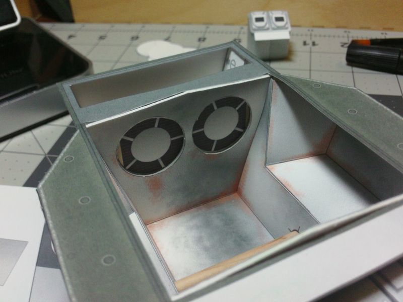 ... Opposite of the rear bulkhead has a full liner now...this wasn't originally planned since visibility is almost non existant... You can see the radiator, which is just flat 2D artwork. Not much point in installing a built up radiator, since this area is almost completely blocked in from view (once the rest of the body is installed). 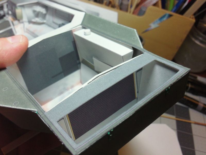 ... Back to the engine bay side, I have installed the Fuel tank with its cutout and heat shield for the engine exhaust. I have not got any plans for the exhaust yet. I need to find some good reference of the what the exhaust actually looks like and how it passes through the Hull. Might be something left up to the builder, not sure yet. 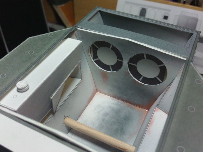 ... Same shot, but here I have fitted the shroud for the Cooling Fans. Twin fans driven by belts, off the front of the engine. 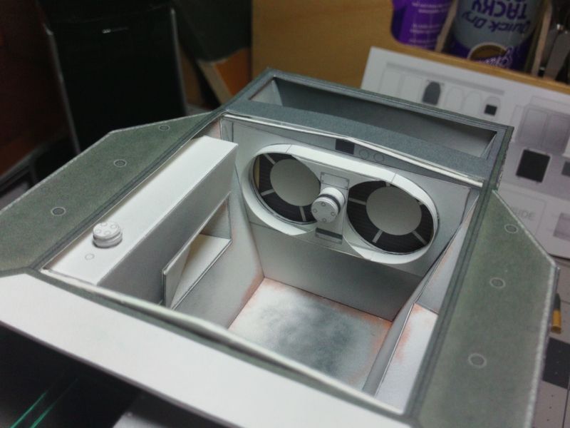 ... And here, I am test fitting the completed fans. Took a few tries to get the look I liked, and to get the blades sized properly. With the radius and angled fit, I kept measuring wrong! They need to fill the openings but be a little smaller to allow for an easier fit. 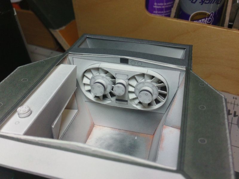 ... I have redesigned the straight 8 cylinder a couple of times. Trying to get the best fit and position. Its notched to fit over, and hide, the dowel axles. It also has to clear the shroud and fans, but there are still other parts to go on, around and behind. I've also added more parts to help simulate some of the drive train. This will all probably go through more redesigns. 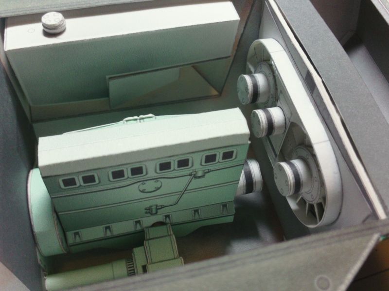 ... Just adding more parts to test positions and clearances. Battery boxes? I'm not really sure. And then theres the upper frame/crossmember to support the closed hatches and the Oil Cooler.. 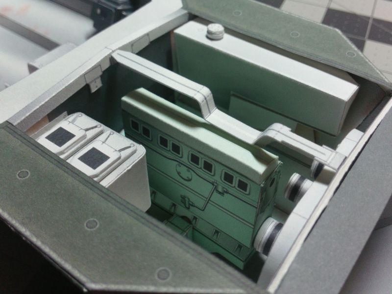
__________________
SUPPORT ME PLEASE: PaperModelShop Or, my models at ecardmodels: Dave'sCardCreations
|
|
#54
05-23-2016, 06:58 AM
|
||||
|
||||
|
Looking there under the hood/bonnet I'm wondering what kind of fuel mileage this thing got and what its horsepower to weight ratio was.
Wonder if that data is posted out in web land anywhere? Back after having found something, Quote:
Okay, 72kmh = about 45mph, 400km = about 250 miles. Question is, is that 10 tons imperial or metric?
__________________
Screw the rivets, I'm building for atmosphere, not detail. later, F Scott W
|
|
#55
05-23-2016, 07:17 AM
|
||||
|
||||
|
In my profile book, it shows:
Total Gross Weight = 25,536 lbs (12.77 tons) Power = 160 bhp gross Max Speed = 45.5 mph Safe speed = 30 mph Average Fuel range = 250 miles (on roads) / 160 miles (cross country) Average Fuel consumption = 4.7 mpg (road) / 2.6 mpg (cross country) So performance is not great...and economy is much worse. Not a great car pool choice. LOL But it does have five speeds forward or reverse. Oh, and did I mention it has weapons?
__________________
SUPPORT ME PLEASE: PaperModelShop Or, my models at ecardmodels: Dave'sCardCreations
|
| Google Adsense |
|
#56
05-23-2016, 09:55 AM
|
||||
|
||||
|
As I mentioned way back in post #6 ... it's soft skinned cousin 'Stalwart' could do 80 mph cross country ... fly off the river bank into the water, then keep going at 5 knots. I wouldn't want to pay it's fuel bill though.
Bin there ... done that ... excitin'.   
__________________
Keep on snippin' ... Johnny
|
|
#58
05-29-2016, 07:18 AM
|
||||
|
||||
|
Another Update...
still working at adding objects to the Engine Bay. Just like the Centurion, I'm trying to add just the larger, more obvious shapes to the area. I'm not worrying too much about technical accuracy...but I am working off actual photos of the real thing. I don't want to put something totally in the wrong place! The overhead "Cooler" is proving to be a bit of a pain. An awkward position to attach the finished part (under the side deck) but it also has to align with the center Brace cutout and clear the Engine Covers. I think its an Oil Cooler? This Engine doesn't have a Turbo...that I can see.  ... The Cooler also has to lift...well it doesn't "have to", I just wanted to make it moveable. So that factored into the mounting bracketry and a simple hinge design. I've still got some objects to add closer to the Fans. I believe there are a couple of Canisters or Filler Tubes in the empty area behind the Cooler. Note the Exhaust... I resized the pipes...resized the flange plate...finally found the right angle and length to clear the Fuel tank.  ... On the topic of Exhaust, I had no idea how the Exhaust went under the Fuel Tank or exited the vehicle. I held off positioning the Exhaust Pipes until I understood. Could not find a photo of that side of the Hull...until now. Looks like the twin exhaust pipes are connected...probably a Y-pipe... and then a single exhaust tube exits the Hull through a welded opening in the side. Because the pipes are hidden under the Fuel Tank, I didn't bother with the Y-pipe. The outside opening is hidden under the Side Fenders and Skirts and behind a sealed Muffler unit, so I didn't need to get too complicated here. But, for now I have added a small tube which is the exit point for the Exhaust tube. On the final print model, I'm adding more 3D graphic detail. 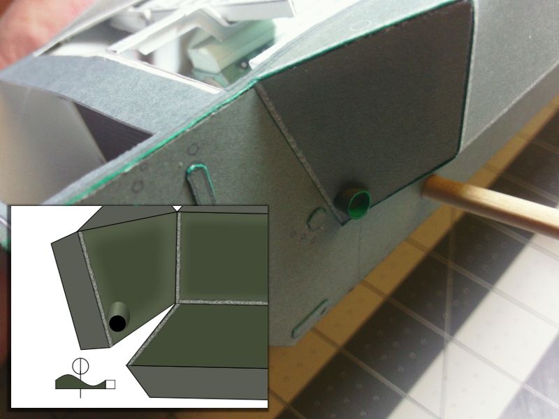 ... I also added more (unseen) Cockpit details...two little Gauge Panels on either side of the Steering Unit. Once the upper Hull parts are in place, I'm sure none of this will be visible (lol) but what the heck. 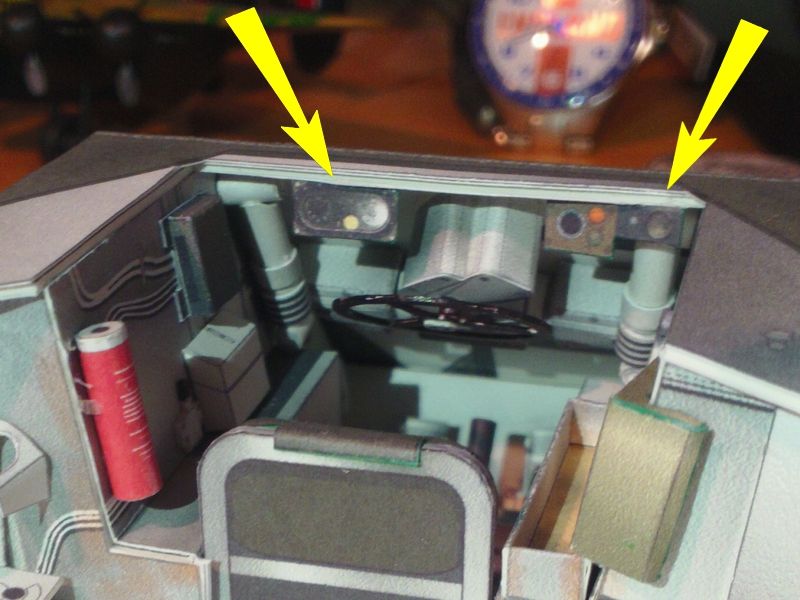
__________________
SUPPORT ME PLEASE: PaperModelShop Or, my models at ecardmodels: Dave'sCardCreations
|
|
#59
05-30-2016, 10:02 AM
|
||||
|
||||
|
I've added a few more little details.
The Oil Filter Canister (below the Oil Cooler). Another Canister or Fill Neck Tube (beside the Oil Filter). Some outlets on the Radiator (above the colling fans). And the Radiator Fill Tube on the opposite side of the Radiator Fans. I think thats enough "stuff" in the Engine hole...enough to satisfy visually? Still some room to modify. Not technically perfect, but most of the obvious components are in their general locations. Time to start working on the upper Body/Hull. 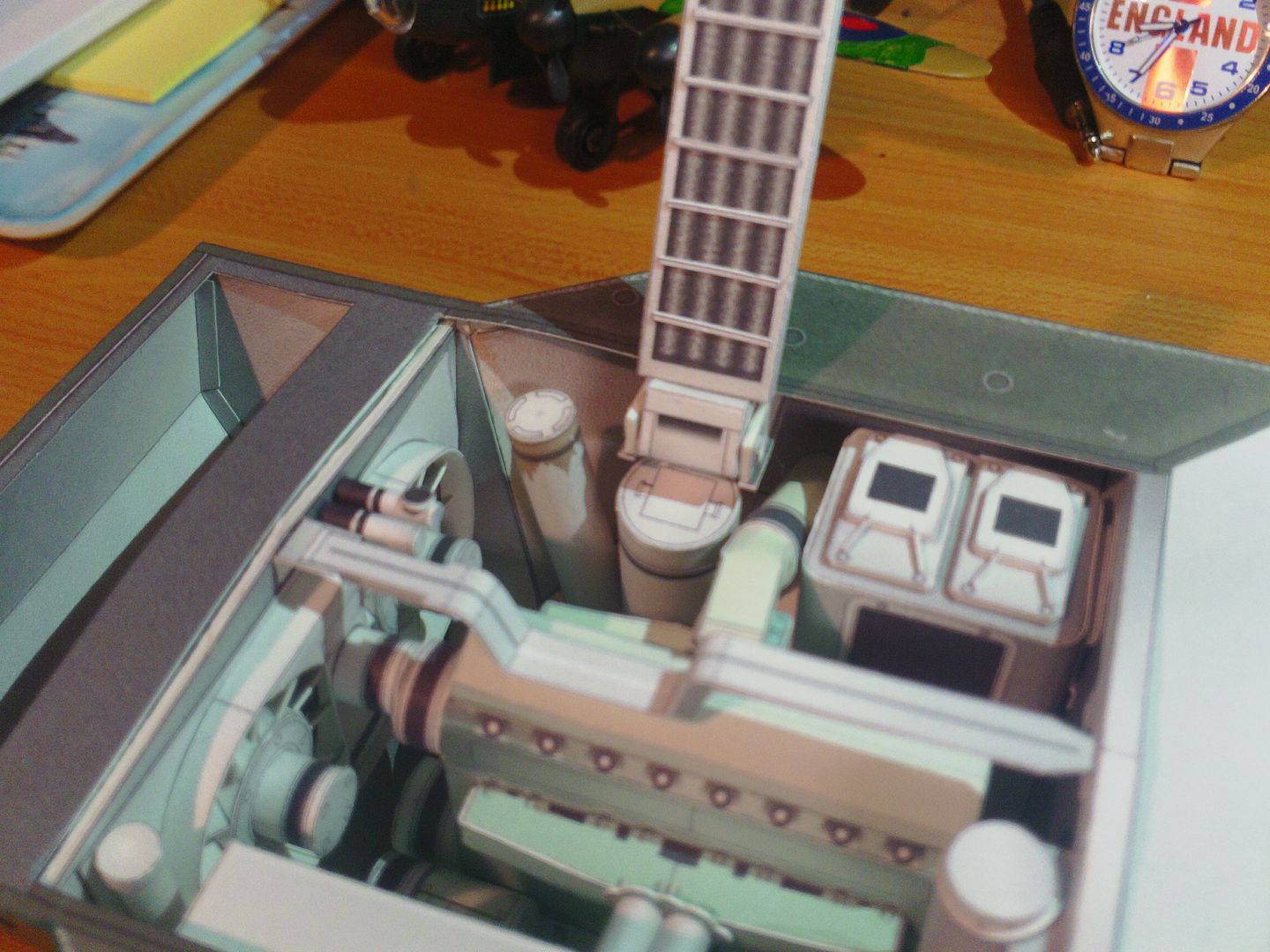 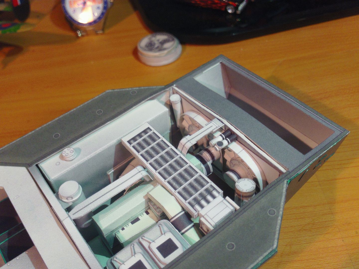
__________________
SUPPORT ME PLEASE: PaperModelShop Or, my models at ecardmodels: Dave'sCardCreations
|
|
#60
05-30-2016, 01:11 PM
|
||||
|
||||
|
Quote:
|
| Google Adsense |
 |
| Tags |
| saladin, armoured, car, project, centurion, scale, started, model, matchbox, 1/16, dinky, design, work, toys, tank, issue, basic, kit, profile, army, number, issued, remember, printing, reference |
|
|


 Linear Mode

