


|
|
|
#41
 10-10-2016, 03:07 PM
|
||||
|
||||
|
Well, now I have a dilemma. I installed a new router today, with the usual difficulties. Of the eight router-dependent devices I have in the house, 6 are installed correctly, but -- you guessed it -- the wireless printer is not one of them. It appears that I have to go over to the computer store and buy another cable to correct this problem, and although the computer store is not far away, I'm not going to make it over there today. Meaning, although I don't mind making another chassis, I'm going to have to wait a day or two before I can print it. To make things slightly worse, I messed up a part on my other current project and need to print it again as well. (In my defense, the other project has some of the most bizarre design decisions ever -- the seam is on the leading edge of the wing for no conceivable reason.)
As for how this happened, I'm not really sure. I followed the instructions about drawing the centerline and took great care to line everything up. I can only assume that I was a little too -- careful? -- about this operation. I'll see if I can do better on try #2 later on. 
|
|
#43
10-10-2016, 05:24 PM
|
||||
|
||||
|
Update -- went to computer store, bought wrong cable, printer still not working. Why would Canon put TWO USB ports with 2 different connector styles on a printer? Needless to say, the obvious one one on the front of the printer wasn't the correct one.
|
|
#44
10-11-2016, 05:25 AM
|
||||
|
||||
|
Quote:
 Back on topic -- did you know there wasn't a printer on the Lunar Rover?
__________________
Christian
Bristow
|
|
#45
10-11-2016, 12:30 PM
|
||||
|
||||
|
67lb Neenah "cardstock" is (if I am correct) COVERstock.
Its smoother and thinner than 65lb cardstock, which is what I use. (Cardstock is also slightly cheaper...I like Staples brand...they have both 65lb card and 67lb cover)) When designing, I usually plan for .23-.25mm (65lb cardstock + glue) thickness. I, personally wouldn't use anything heavier/thicker (like 110lb card) for this particular model. ........... Quote:
__________________
SUPPORT ME PLEASE: PaperModelShop Or, my models at ecardmodels: Dave'sCardCreations
|
| Google Adsense |
|
#46
10-11-2016, 04:12 PM
|
||||
|
||||
|
Oh happy day -- I got the right cable, for the right socket, and from there resetting the network settings was actually quick and painless, and the instant I finished, the printer happily spit out a fresh copy of the Lunar Rover (it remembered!). So I'm back in action.
On this model I've been using Wausau 67# Exact Vellum Bristol, which is the best stuff I have in stock. Usually I use Staples 67# Cover Stock, and it works fine for me (or I'm not very discriminating). Thanks for your explanation, Lighter --very helpful. The one on front has a USB symbol (that asymmetric trident thing) and accepts a USB connector, but what do I know? I'm completely ignorant about Firewire. I do as much printing from my iPad as from my desktop, so for my needs a WiFi printer was necessary. Back to the workbench after dinner
|
|
#47
10-11-2016, 04:47 PM
|
||||
|
||||
|
Continued...
Now build the four (front and rear) Tires/Wheels. Parts included are 4 tire treads, 4 Tire inner strips, 4 inside Wheel faces, 4 outside Wheel faces. 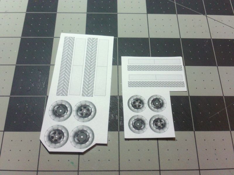 ... As always, use a knife and metal straight edge for the best (straighest) cuts. Cut out the four Tread parts and four inner strips. 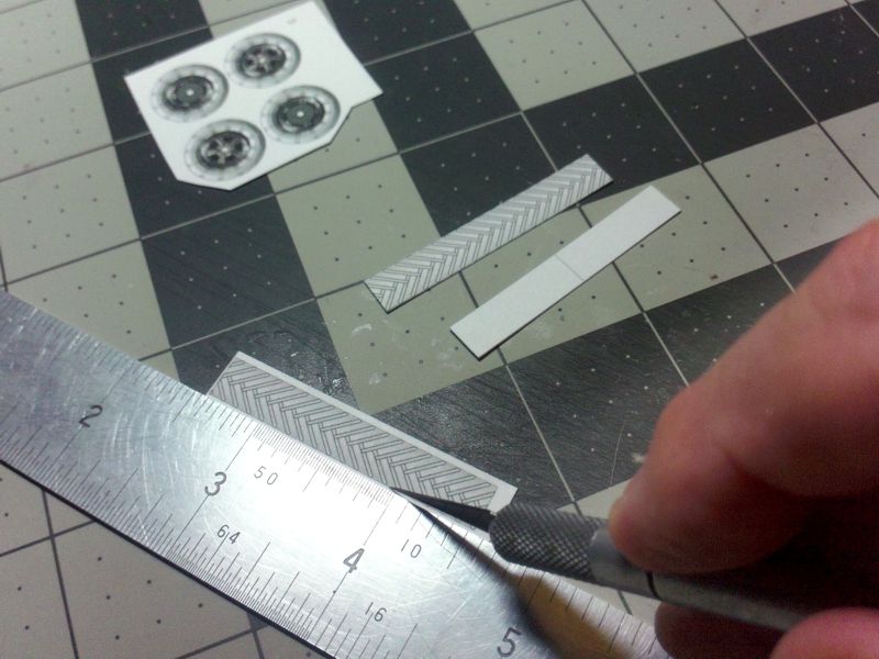 ... Cut out the Wheel faces using scissors or knife...its up to you. Just cut them as circular as possible! 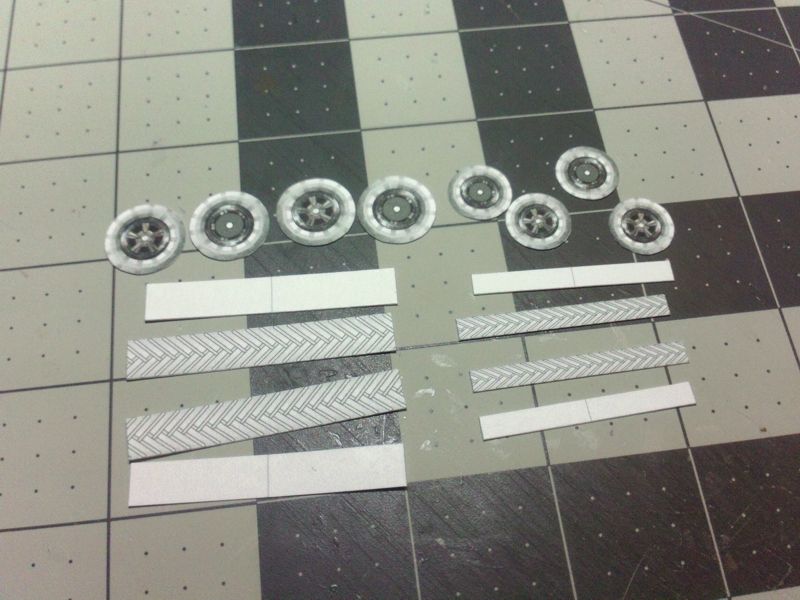 ... Use a wooden dowel or cylinder to precurve the eight Tread parts. 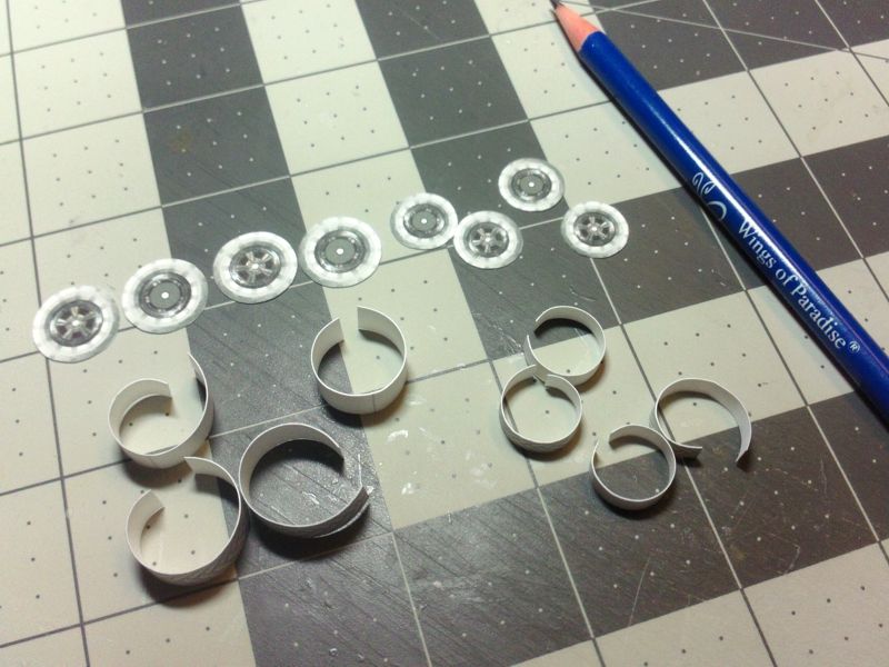 ... To assemble a Tire tread...glue one end of the tread strip to the inner strip at the center line. Try not to flatten out the curved part. 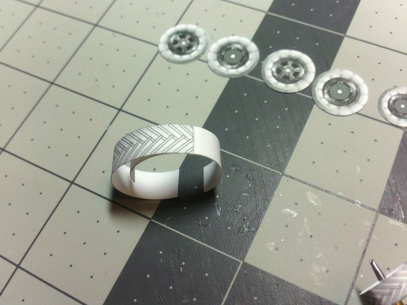 ... After sufficient time for the glue to dry, roll the inner strip tighter than needed... wrap the Tread part around until it meets the opposite end, and glue in place. Goal here, is to get a tight seam of the tread part. Don't worry about the inner strip just yet. 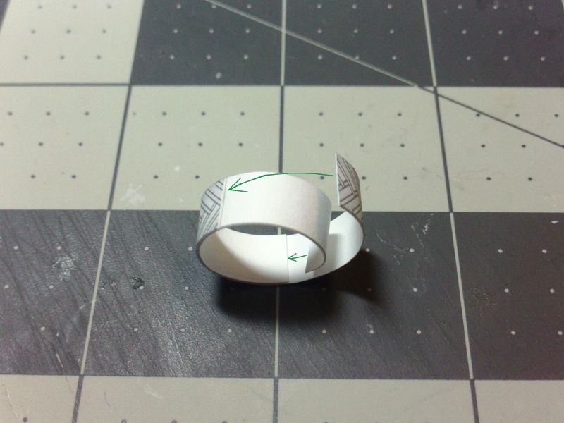 ... The inner strip can be glued in place...or just the ends can be glued...its all optional. If the outer tread strip is cut and joined correctly, the inner strip will fit perfectly, and the inner strip just adds thickness to attach the wheel faces. 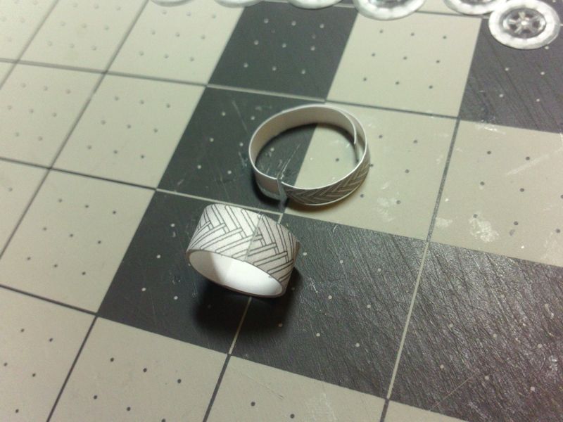 ... Once the tread parts are attached, slide the hooped parts over a dowel of the correct size. Allow the glue to cure, while the part is supported in this way. It will help to impart a circular shape into the parts. It will make attaching the wheel faces a lot easier! 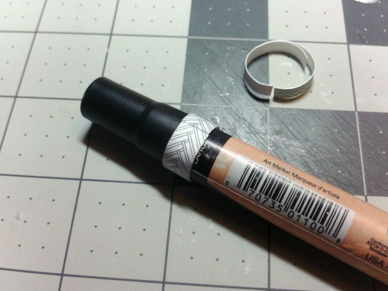 ...
__________________
SUPPORT ME PLEASE: PaperModelShop Or, my models at ecardmodels: Dave'sCardCreations
|
|
#48
10-11-2016, 04:48 PM
|
||||
|
||||
|
Four Tread hoops and eight wheel faces ready for assembly.
The Tread hoops curing before assembly. 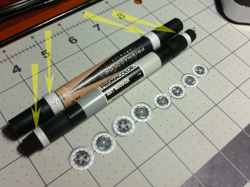 ... To attach the wheel faces apply a thin bead of glue on the edges of the Tread hoops.  ... Attach a wheel face to the Tread hoops...center it and allow to dry completely. Keep an eye on the circular shape of the tread hoops and adjust as necessary until the glue grabs. Don't mix up the wheel faces...try fitting four inside or outside part first. Then, when one side set of faces is properly secure, attach the opposite sides. 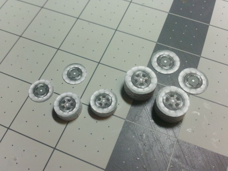 ... To attach a Fender to each Wheel, just line up the center hubs on the backsides of each wheel to the hubs on the fenders. 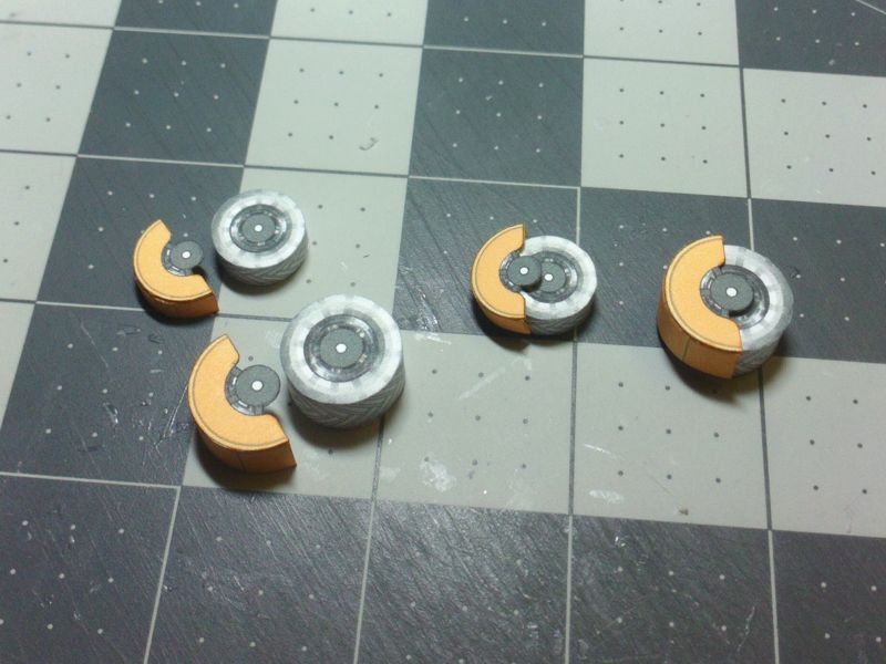 ... Apply glue to the center of the hub (on the inside of the fender)... and apply glue around the edges of the glue tabs (to contact with the Tire). 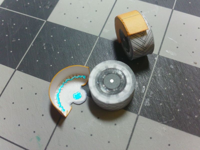 ... Press the fender onto the tire making sure the Hubs are aligned. Also pay attention to the top/bottom of the tires. The shaded edge of the Tire wall is the bottom of the tire (visually). Since the Wheels do not rotate on the model, position them correctly for the best visual effect. 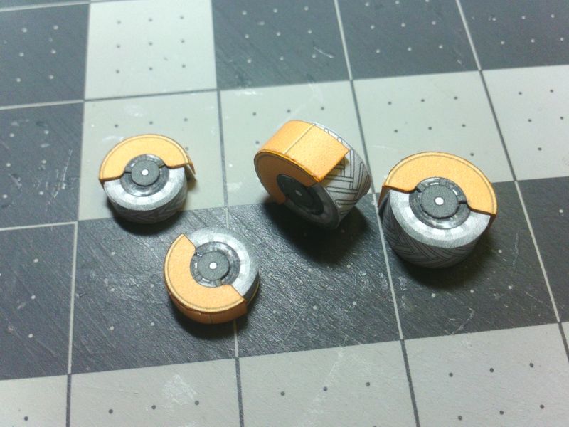 ...
__________________
SUPPORT ME PLEASE: PaperModelShop Or, my models at ecardmodels: Dave'sCardCreations
|
|
#49
10-11-2016, 04:56 PM
|
||||
|
||||
|
While the Fenders/Wheels cure, lets assemble the parts for the center area of the Rover.
The Driver's Console and the Seats. Remove the necessary parts from the model sheet: Center Control Console and support tube. 2 Seat bases, 2 Seats and 1 Driver's Harness 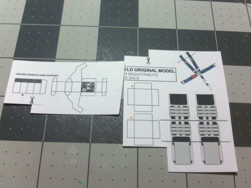 ... Starting with the seats... the seats are scored and folded (one valley fold and one mountain fold). 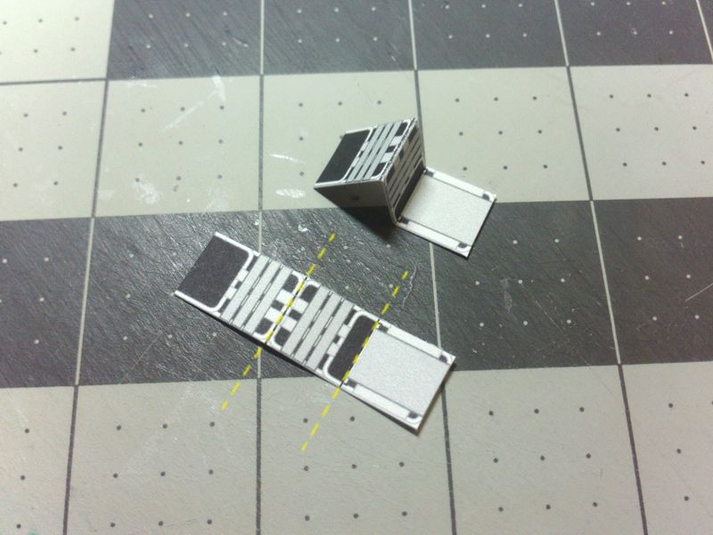 ... Glue the seat backs. 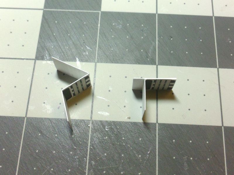 ... Score and fold the seat bases. 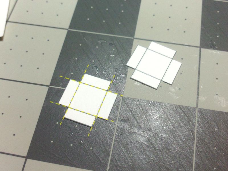 ... Glue the corners of the seat bases...you have two options: edge glue the side, at the corners. Since these parts are so small, edge gluing is not very difficult. Or, cut some small tabs, score and fold them, and glue them in place at each inside corner. Takes time, but works well. 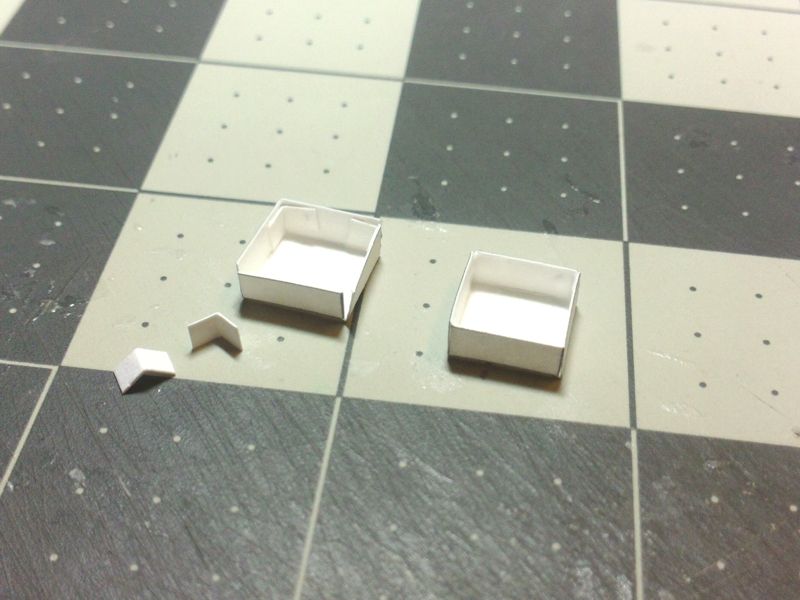 ... Once the seats are glued securely...and the seat bases are glued and secure... mount each base to the bottom of each folded seat. Just slide to the rear, and glue to the underside of the seat. 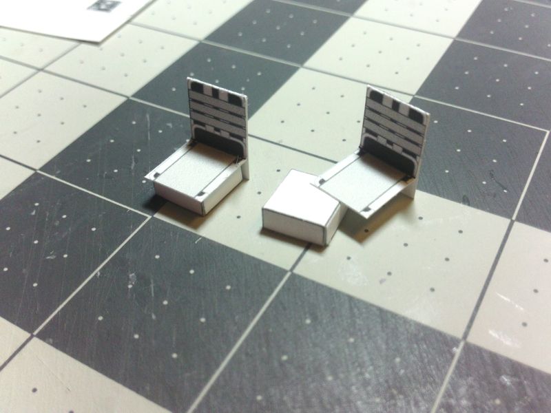 ...
__________________
SUPPORT ME PLEASE: PaperModelShop Or, my models at ecardmodels: Dave'sCardCreations
|
|
#50
10-11-2016, 04:58 PM
|
||||
|
||||
|
For the Driver's Control Console, there are a few folds...
mostly Mou ntain folds, but there are a couple of Valley folds. Just make sure everything is scored and cut out the parts. 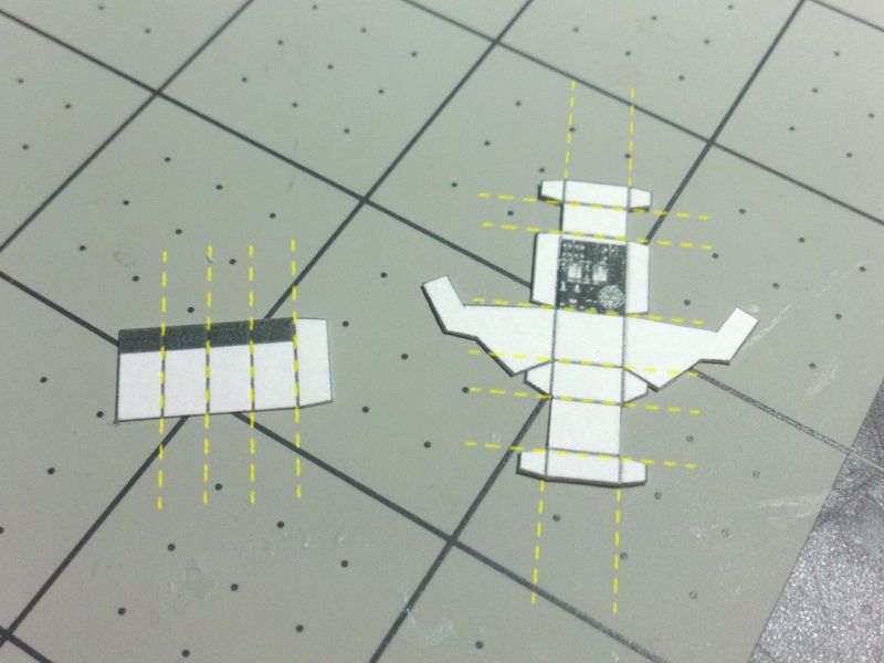 ... Fold the Console support into a square tube with an underlapping glue tab. Fold the Consolde sides to create a sharp edge fold. The three smaller (side) parts are glue tabs. 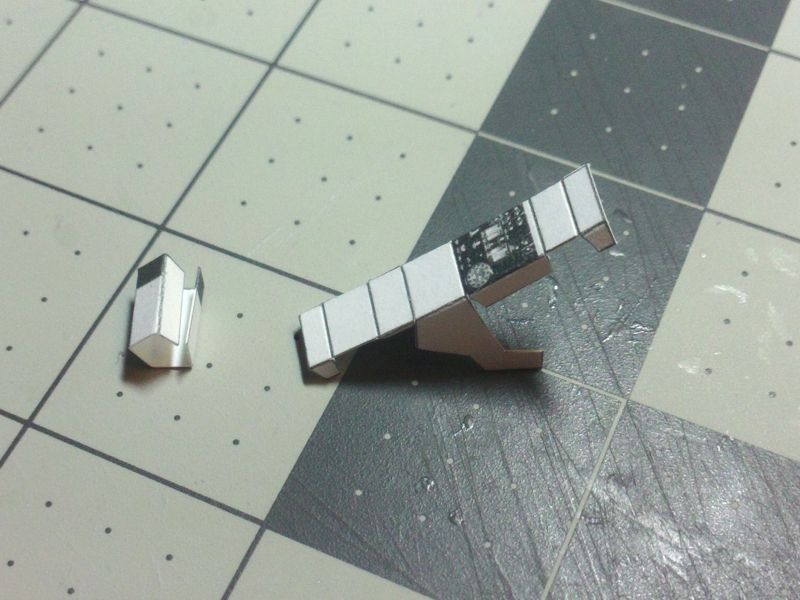 ... Glue the Console support tube. Unfold the side tabs on the Console part and start folding the central folds. Again, this is to impart folds and shape to the part. 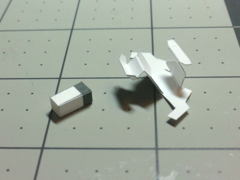 ... Focus on one side of the Console part, and glue the side tabs in place (up to the center of the part). In the photo, you can see I started with the three front faces of the console. (The Console is shown upside down, with the base opening at the top) Take your time to keep it all square! 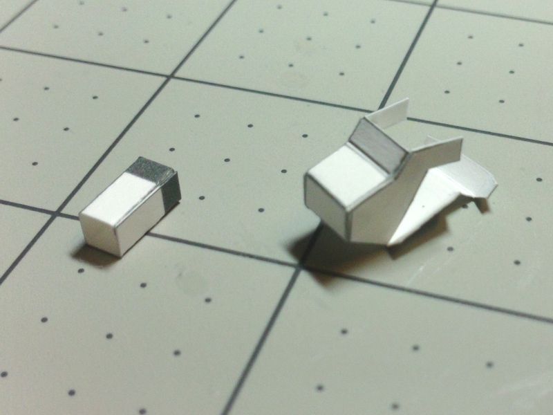 ... Wait a sufficient amiount of time for the glue to setup properly, then glue the remaining faces of the Console. In the photo, the Console is now upright, and you can see I glued the Instrument Panel and remaining two faces. 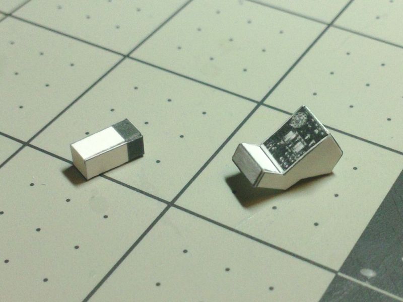 ... Now, insert the Support Tube and glue in place underneath the Console. The black coloured end of the tube illustrates how much is hidden in the Console. Just edge glue it to the underside the Console...centering it in the opening. 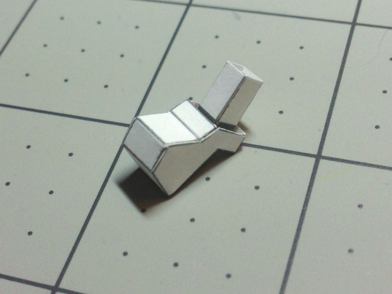 ...
__________________
SUPPORT ME PLEASE: PaperModelShop Or, my models at ecardmodels: Dave'sCardCreations
|
| Google Adsense |
 |
| Thread Tools | |
| Display Modes | |
|
|


 Linear Mode

