


|
|
|
#91
 05-23-2019, 10:39 AM
|
||||
|
||||
|
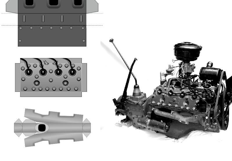
I started working on the Engine and Transmission yesterday.
after getting the basics of the engine sorted out, I quick built a block and gearbox to check the size and alignment in the chassis. It just barely squeezed in between the two connecting cross-members... and I am unhappy with the length of the engine. I don't have any real plans or blueprints that show me the exact position of things... so, after some careful analysis of various photos of the real thing, I decided that the front cross-member needed to move forward slightly. This would give me 2-3mm extra room. So I gently sliced and diced ...and cut out the part from the Frame...did a little touch up...and refitted the cross-member in the new position. (Of course, I adjusted the Parts in the kit to reflect this change.) But I was still unhappy with the available room, and after trying to modify the Engine assembly, I took another look at my reference photos. It was obvious that the second cross-member (at the back of the Transmission) should move rearwards. Mine was definitely too far ahead...and so, I cut that one out too! And moved it back 4mm. The damage to the frame is minimal...the touch-ups are not that visible...I won't be bothering to build another Chassis! But now I have an additional 7mm to work with. At this scale, thats like adding 11.2cm!! (almost 5 inches!) New engine and Transmission parts have been printed. A new build will begin! 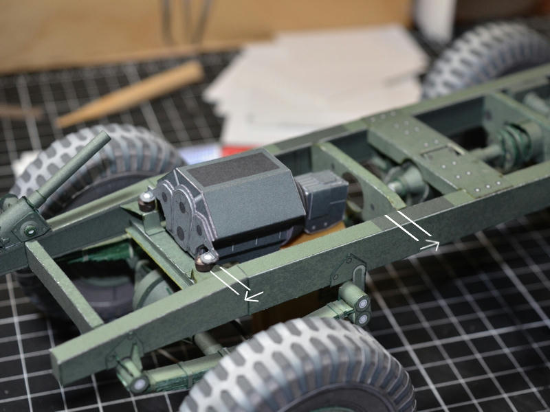
__________________
SUPPORT ME PLEASE: PaperModelShop Or, my models at ecardmodels: Dave'sCardCreations 
|
|
#92
05-24-2019, 05:35 PM
|
||||
|
||||
|
If I cut out this front cross-member one more time...the frame will collapse!!
Seriously...after moving it forward, I decided to lower it, since the real thing is curved and deflected downwards (for extra engine clearance). The engine doesn't actually sit on top of it, but the crank pully comes very close to it. My engine is very close to the crossmember , and I will need extra clearance for the pulleys and front engine parts. I didn't want to redesign and make the shape more complicated to build, so lowering is a trade-off. It actually looks more like the real thing now. But...I forgot to raise the engine mounts, so I had to cut it out again and install another one! ... With the cross-members sorted, I started on a new engine and transmission design...and a quick build of the basics... 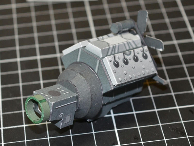 ... I think I have enough room for the front pulleys, belts, etc, so lets give them a try. These Pulley and Belt parts are double layered, and spaced by little round spacers. Very small, 3mm circles that are quadruple layered. The Fan belt layer is spaced with only a double spacer under the lower pulley. I was going to do layered pulleys and a separate Fan, but it all got very complicated, and too many parts. This is finicky to cut out, but much simpler to build. 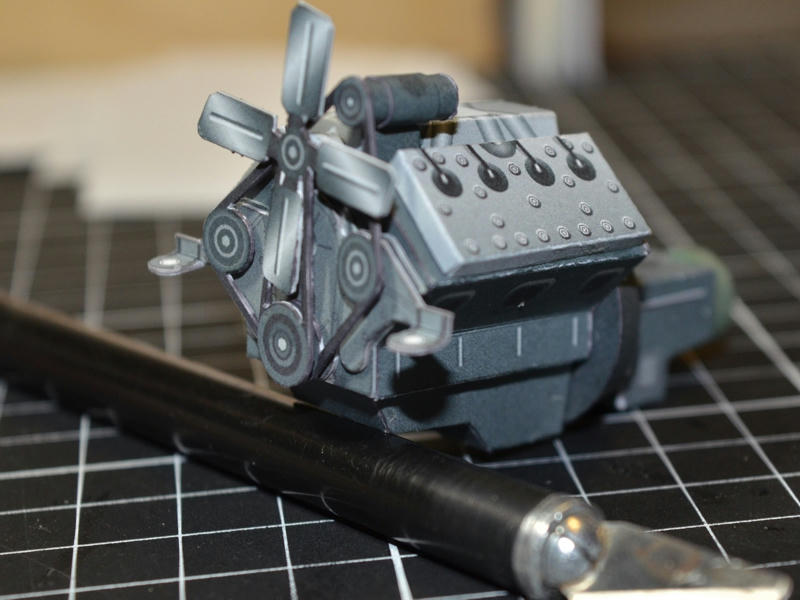 ... A few more detail parts added...and then a test fit into the Frame. Once I got the driveshaft sorted out, everything dropped into place. Well, almost dropped into place. My Transfer Case and driveshaft alignment isn't perfect...the byproduct of this test build and various modifications as I go. The kit parts all have the proper dimensions and should all fit together more easily (if assembled correctly). 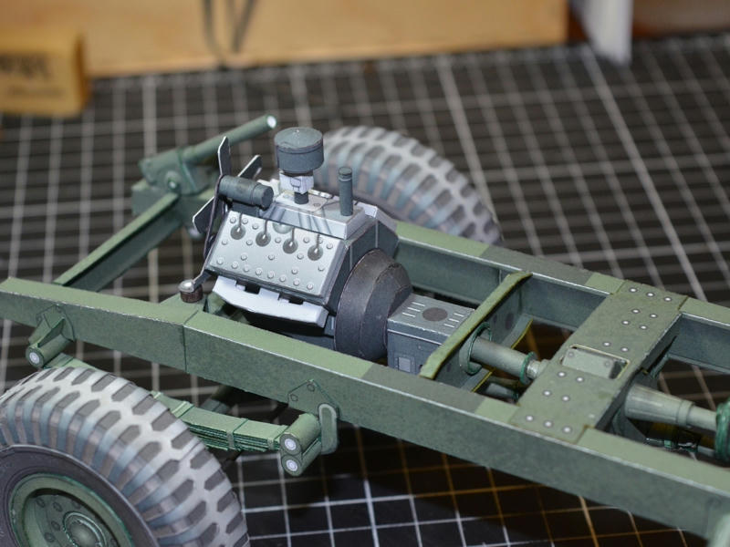 ... I started out with the intention of creating a very simple, boxy and stylized Engine. I only wanted the impression of a drivetrain (when viewed from underneath), so I wasn't planning on all these details. But, as I keep working on it...it keeps getting more complicated. And I keep adding more details. Got a few more parts still to go on, but you get the idea. I fitted some boxy exhaust manifolds to the engine, but I wasn't planning on adding a full exhaust system (since the paper pipes will be very narrow, with many connections and bends). My original idea was to fit just the Muffler at its proper place. But now I'm thinking I will design the full exhaust system and leave it up to the builder to add it or not. 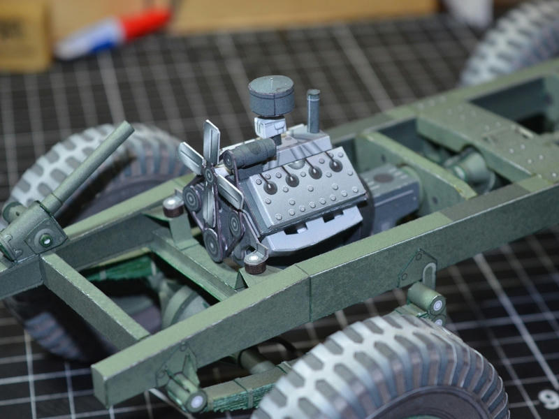
__________________
SUPPORT ME PLEASE: PaperModelShop Or, my models at ecardmodels: Dave'sCardCreations
|
|
#96
05-25-2019, 08:02 AM
|
||||
|
||||
|
22 looks better.
Actually I have one photo that you can only count 22...I just checked twice! But I never really thought about it...just laid them out in a balanced pattern. Anyway, easy fix to redo the pattern. ... I added a Starter Motor last night...and I am rethinking the Exhaust Manifolds. They are too boxy....but I didn't want to resort to tubes or anything more complicated. I'll think some more as I work on the Exhaust Pipes. 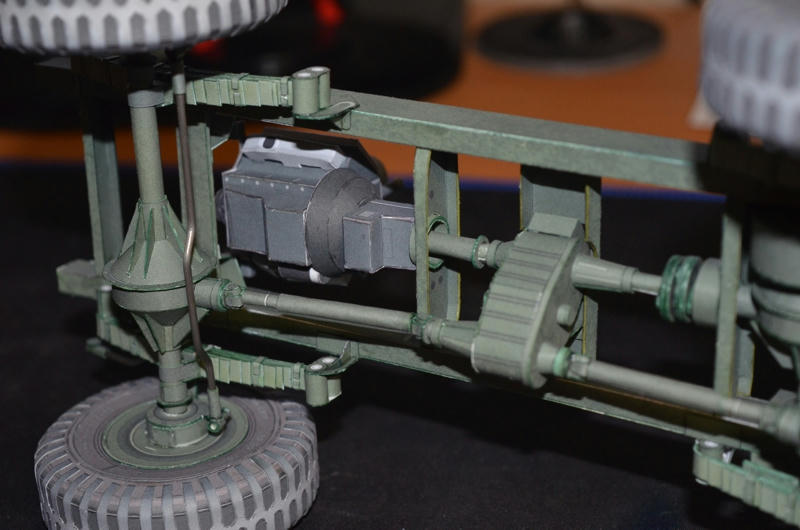 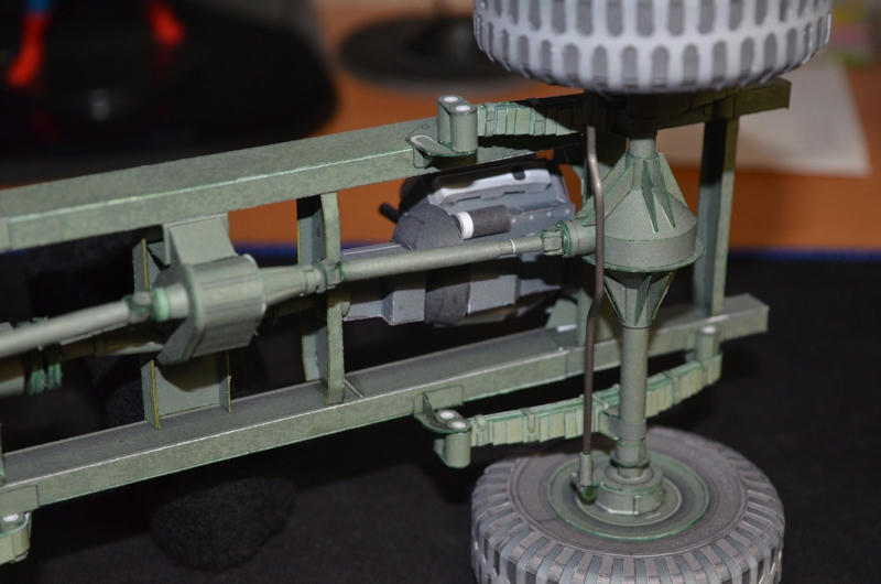
__________________
SUPPORT ME PLEASE: PaperModelShop Or, my models at ecardmodels: Dave'sCardCreations
|
|
#97
05-25-2019, 09:00 AM
|
||||
|
||||
|
Still think this chassis is a model on its own, the body is going to be an 'extra' to this. Great build, and good, clear pics of the work.😸😸😸
__________________
"It's all in the reflexes."
|
|
#99
05-25-2019, 02:19 PM
|
||||
|
||||
__________________
SUPPORT ME PLEASE: PaperModelShop Or, my models at ecardmodels: Dave'sCardCreations
|
|
#100
05-27-2019, 01:00 PM
|
||||
|
||||
|
So, everything is on hold at the moment.
I just received information that the back end Towing hardware on my Chassis is NOT a Ford setup. Supposedly its a Chevy FGT setup. Which is funny because I just photographed a Chevy Gun Tractor with something entirely different. (see the attached photo) I'm not arguing...I'm no expert...thats why I ask for help. But I'm hoping I will receive some more information (photos) to help me decide what to do. Redesigning the kit (and model) is not a problem. Rebuilding this prototype is. I am able to cut off some parts...some times... but there might be too much to modify, and as a result, might require building a whole new Frame. Which, at this point, I really don't want to do. But, I never release a kit without at least one attempt to build what is in it. So if I change something like this, I'll have to test build it. Sometimes there are interchangeable parts...was this set-up ever used on a Ford? ...if so, I am good to leave it in place. But if its definitely a Chevy specific set-up, then it will have to be changed. The axles and engine in this FGT are definitely Ford type.
__________________
SUPPORT ME PLEASE: PaperModelShop Or, my models at ecardmodels: Dave'sCardCreations
|
| Google Adsense |
 |
|
|


 Linear Mode

