


|
|
|
#41
 09-01-2019, 08:01 AM
|
||||
|
||||
|
Next...move to the Limber Pole (front)...
The Pole actually is sectioned, and joined, close to the Limber Box. It can be unbolted for storage and/or transport of the Limbers. I start with a simple wrap (single layer) part.  ... Then, the two Plates that bolt together. Each is four layers of card, edge coloured, then glued together, then edge coloured again. Tricky part is cutting out center holes and then sanding to get a tight fit. 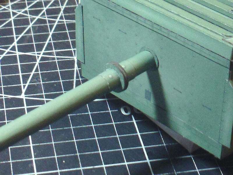 ... Then I add these small gussets for strength. These are double layer card, but very small to cut out and glue in place. 8 of them in total.  ... Moving to the very end of the Limber Pole, a cap plate is added. Assuming you have used a wooden dowel inside the pole, this hides that fact and shows you where to drill a hole. You must drill a hole, into the end of the dowel to receive the Tow Eye. If you didn't use a dowel, your hole should be clear of the Tube wall. But it will be a good idea to add some extra material in this area (to glue against). (In the Instructions, I will really push the idea of using a wooden dowel!) 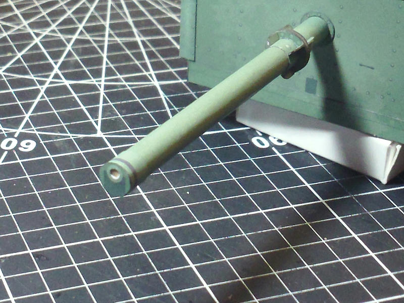 ... At this point, I decided to assemble the front lower Storage Tray (testing parts). Other than the addition of some inside end plates, and a few dimensional changes, this is the final Tray to be attached to the lower front of the Limber Box. But...I will wait until I get the Limber Pole finished. 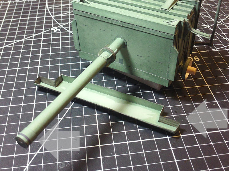
__________________
SUPPORT ME PLEASE: PaperModelShop Or, my models at ecardmodels: Dave'sCardCreations 
|
|
#42
09-01-2019, 09:04 AM
|
||||
|
||||
|
Front end of the Limber Pole again...
another detachable connection, so another single layer wrap and another set of discs. Each ring/disc is four layers again x2. Note the drilled hole to receive the Tow Eye. 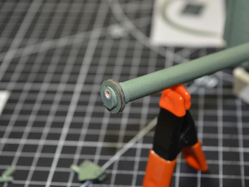 ... First two parts attached to the end of the Pole...these parts go around the Tow Eye, so you could install the lower 'box" part and then fit the Tow Eye, and then install the upper bracket. Or, just make sure the part is shaped properly, and the hole is big enough to receive the Tow Eye. 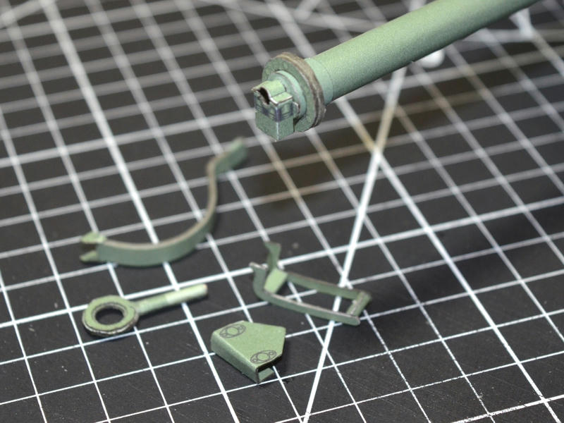 ... I have preassembled the other components... I couldn't properly explain all the components, so I won't bother to try. 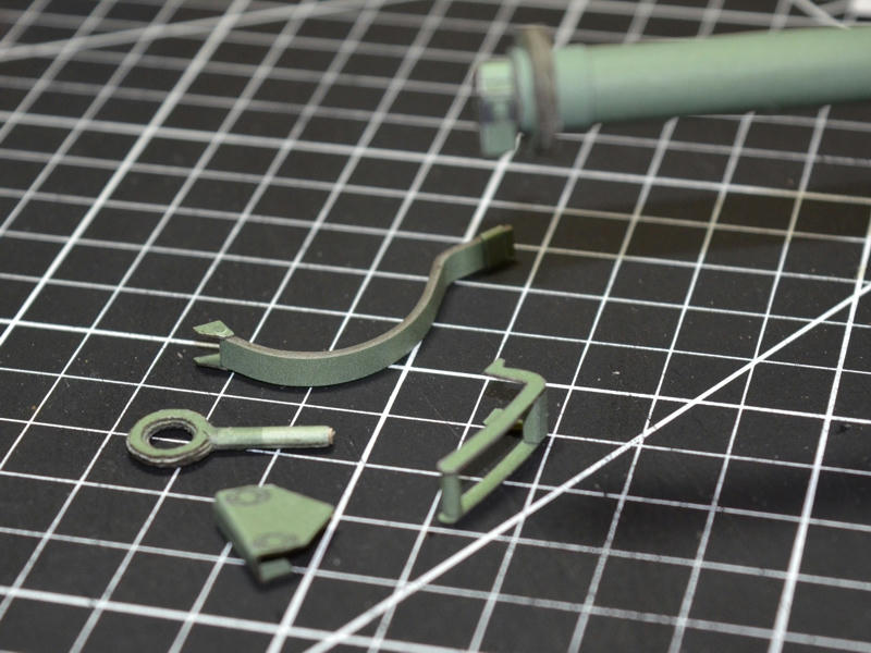 ... a bit stylized, but once assembled, it looks a lot like the real thing! 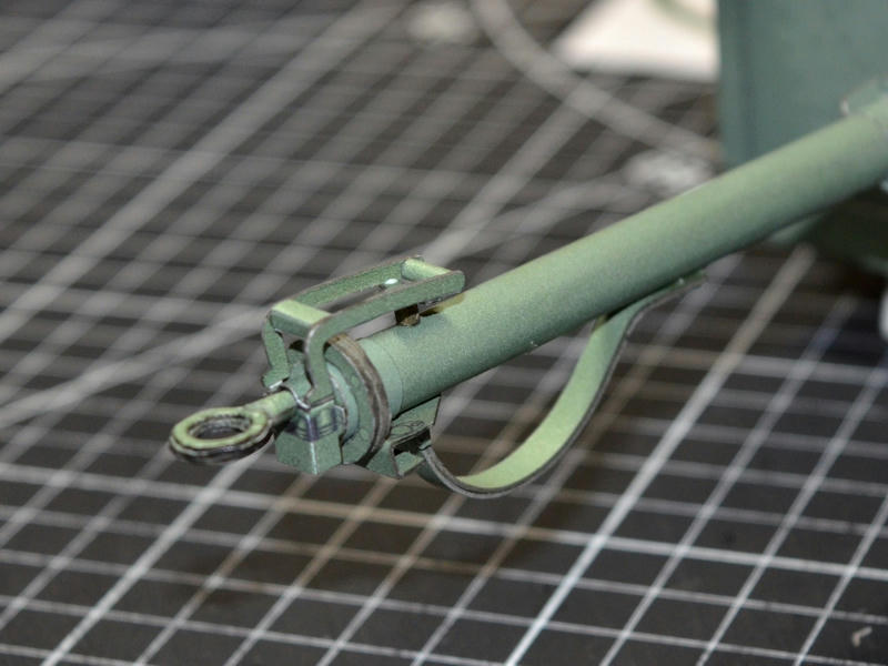 ... I decided the Tow Eye was a tiny bit too small, and i wanted it bigger. I also made an adjustment to the layering, to get a smoother look. Unfortunately I had used some CA Glue when installing the first part into the drilled Limber Pole dowel. And I cannot get it out (to install the updated part). 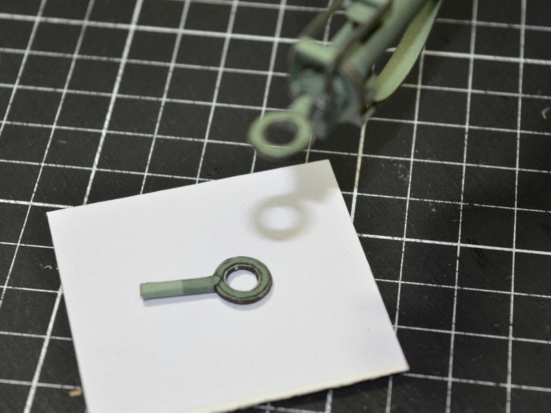 ... Lastly, I glued the Storage Tray to the lower front of the Limber box. It is mounted flush with the bottom, and must be centered horizontally since it is also one of the mounting points for the Wheel Fenders. 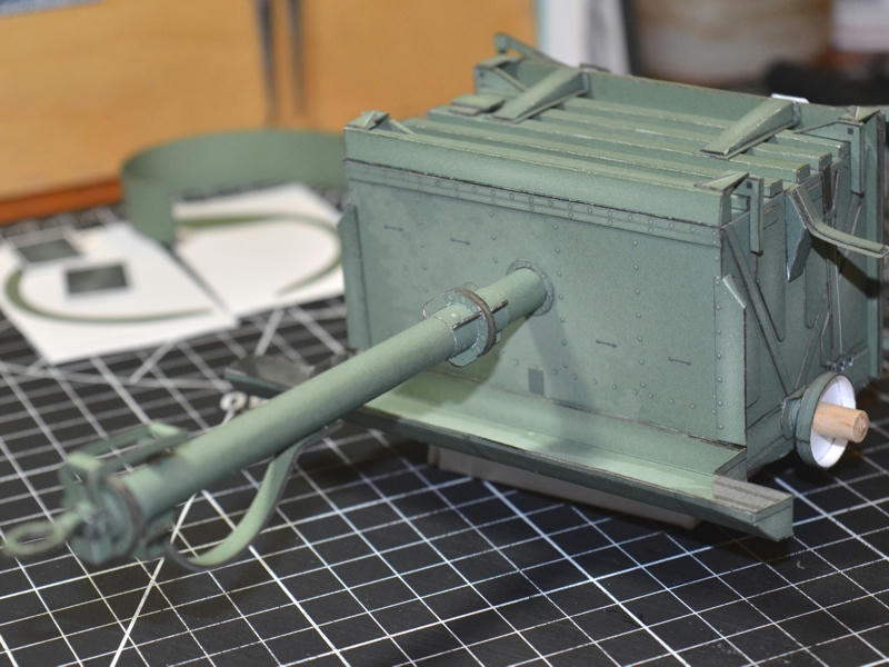
__________________
SUPPORT ME PLEASE: PaperModelShop Or, my models at ecardmodels: Dave'sCardCreations
|
|
#43
09-02-2019, 09:36 AM
|
||||
|
||||
|
We are having a holiday here in the US today.
But I had to tear myself away from the dancers and entertainers long enough to get a look at this work. Again . . . Gorgeous. You get great detail at 1/16 scale. Definitely adding this one to my collection.
|
|
#45
09-04-2019, 10:35 AM
|
||||
|
||||
|
Fenders...
starting with the central Fender part, two layers are laminated and shaped to the proper curve at the same time. The side panels can be used as the template for the shape. I pre-rolled the two layers of the fenders first, using a wooden dowel, and tried to match the shape of the side panels. then I glued up the parts and laminated them together... and immediately starting curving the parts to the correct shape (matching the side panels). As the glue cures, the parts will retain the proper shape. My fenders are extremely close to what they need to be. Then I install the edge strips...two layers, pre-rolled...these will create a thicker 'edge' for receiving the side panels. 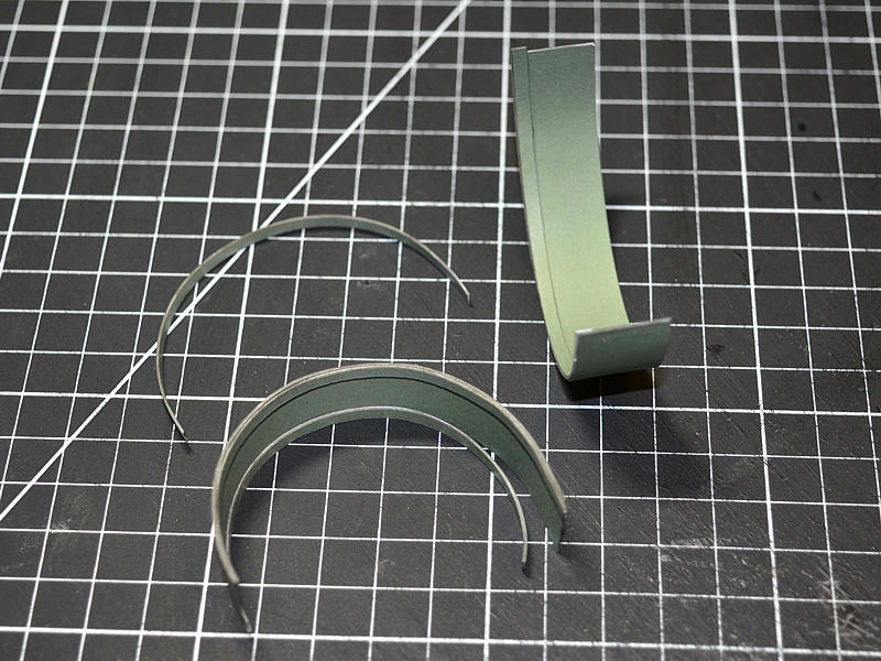 ... Now attach the side panels...I start at one end, and glue about 2-3 centimeters. Let it set up completely...then carefully align the next 3 cm and edge glue it into place. Repeat this method along the entire edge, until the side panel is completely attached. This way, you get the best fit and best alignment of the parts. 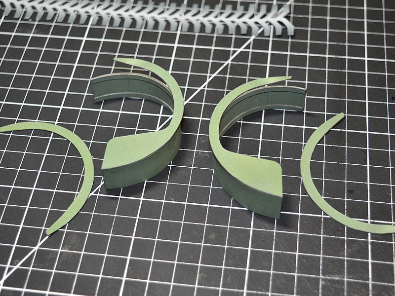 ... After the side panels are installed I added a thin bead of glue at the inner joint for increased strength. After the glue is completely set up, I gently push outwards on the side panels, giving them more flare away from the fender. Gives the fender a bit more of a wider, flared look. I also burnish the outside corner edges (since the real fenders have a rolled/curved edge). 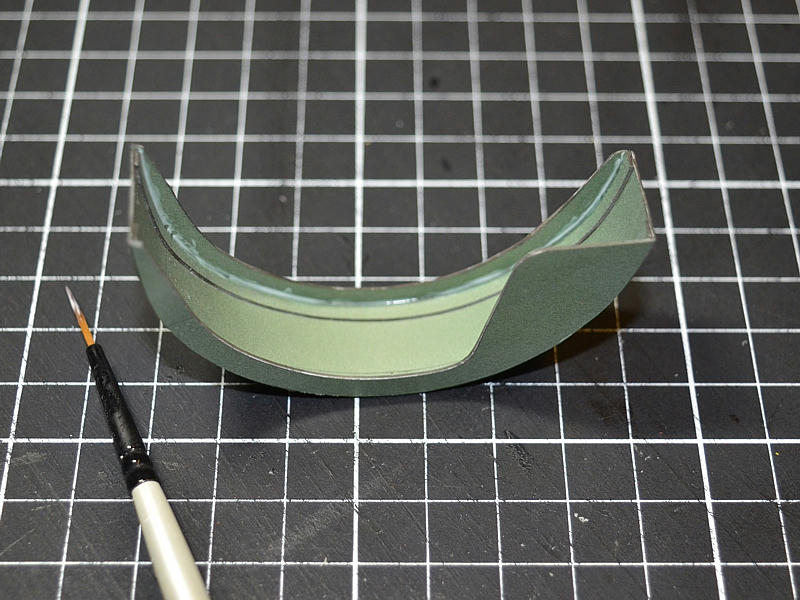 ... Lastly, installed the laminated fender extensions (rubber mud flaps). And the fenders are ready to install. 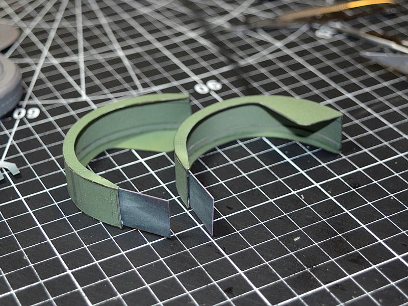 ... Start by aligning and gluing the front/leading edge of each fender to the lower Storage Tray. The fender is roughly flush with the bottom of the Tray, and sits in the corner space created by the Tray. Allow the fender to cure (after gluing in place). 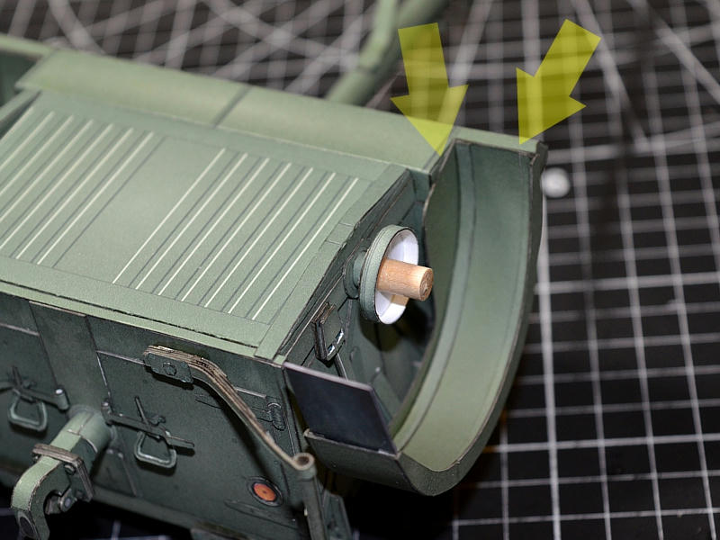 ... Once the fender is securely glued, it can be manipulated into its proper position. I've noticed that real Limbers have slightly varied positions of the fenders. I guess they get get and twisted with use, and an exact position isn't necessary. Regardless, its important to maintain an even distance between the fender and Limber box. Since the rear Plate extends beyond the box, attention should be paid to that area as well. 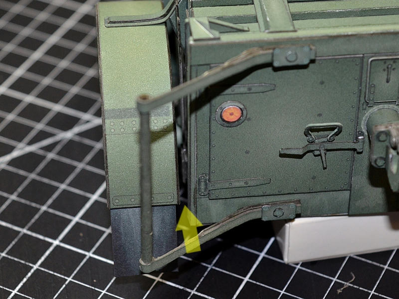 ... Once I have a rough idea of where the Fender should be positioned, I apply glue to the underside of the upper bracket and push the fender up to meet the bracket and lock it into place. There is a rear support bracket still to be installed, but the front and upper mounts are sufficient to hole the paper fender securely and in position. 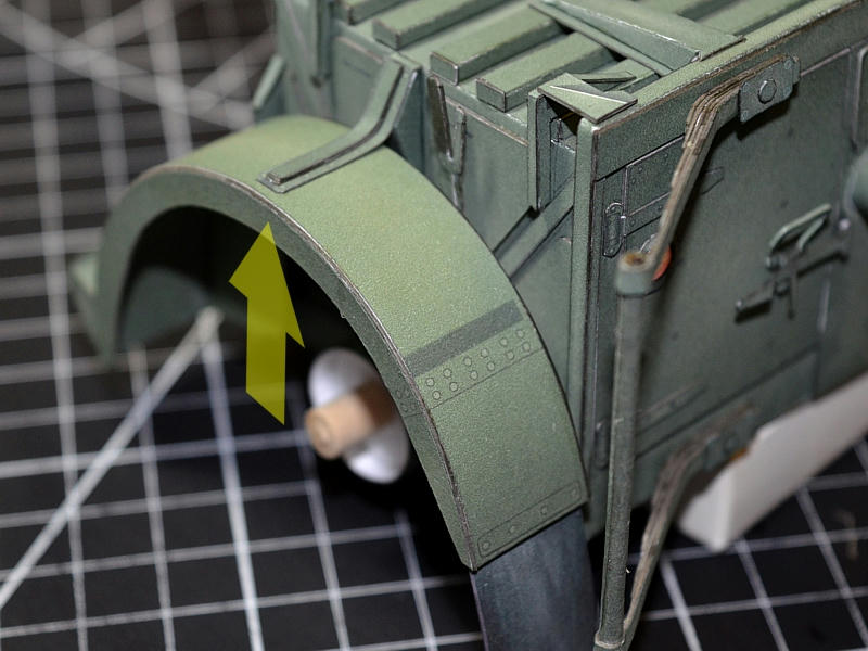 ...
__________________
SUPPORT ME PLEASE: PaperModelShop Or, my models at ecardmodels: Dave'sCardCreations
|
| Google Adsense |
|
#46
09-04-2019, 10:40 AM
|
||||
|
||||
|
Moving underneath the Limber, I will assemble and install the lower spring bump stops.
As far as I know, these are spring brackets that stop the Limber from flipping over backwards. They will mount to the axle hubs, and extend out the rear of the Limber. Three spring layers are laminated together and then formed to the template shape. Simple mounting brackets are attached. The assemblies shown are too long...I readjusted the size and rebuilt these parts. But the assembly method is the same. 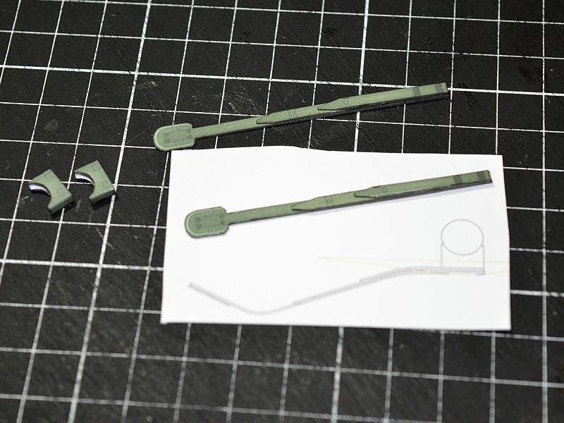  ... Align the brackets level with the Limber and glue to the axle hubs. I readjusted the angles/shape of the Springs at this point. 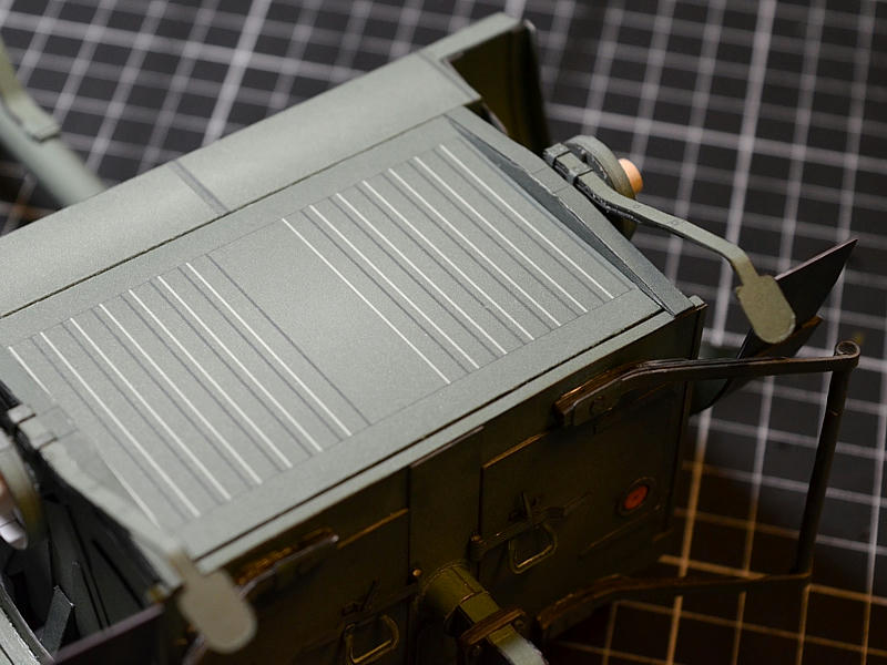 ... Its hard to photograph the "bump stops" as they extend from under the Limber. You'll also notice the rear fender brackets installed. These are glued to the fender and then extend up to and behind the rear Limber Box plate. The ends of the brackets are twisted and shaped until they meet the plate. My brackets are a bit too short....I have extended the parts in the kit. As I said before, they are required for actual support since the paper parts are light and rigid and securely mounted up front.  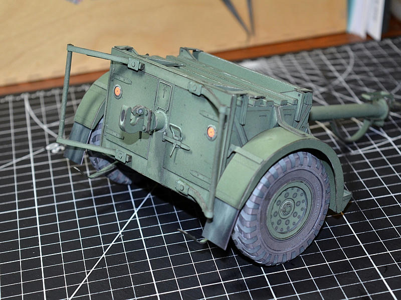 ...
__________________
SUPPORT ME PLEASE: PaperModelShop Or, my models at ecardmodels: Dave'sCardCreations
|
|
#47
09-04-2019, 10:42 AM
|
||||
|
||||
|
Last thing to do is install the Tires/Wheels.
These wheels are basically a downsized version of the Tractor wheels. Assembly is exactly the same, only with slightly smaller parts. (So I didnt bother showing the tire and wheel assembly) The Quad wheels are 20" rims, size 10.50 tires. Whereas the Trailers are 16" rims, with 9.00 tires. With the wheels in place, the Limber can sit in resting/unhitched position. 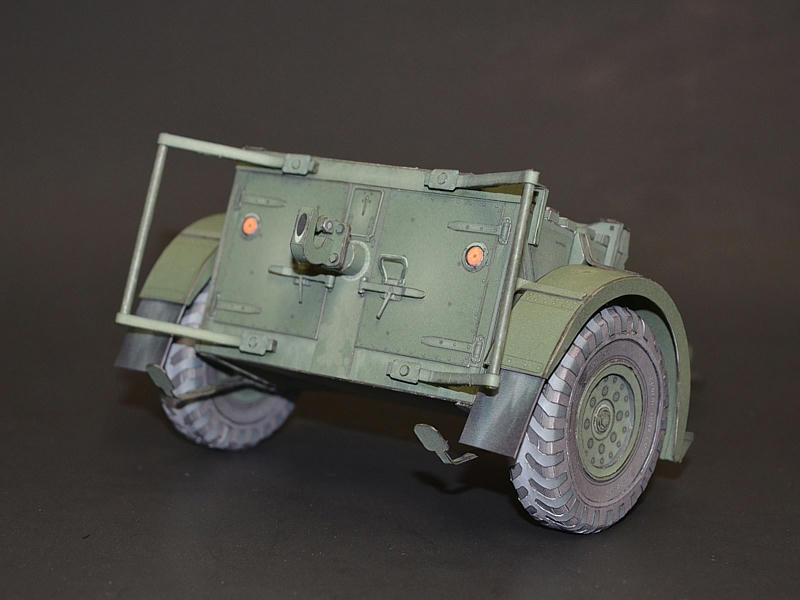 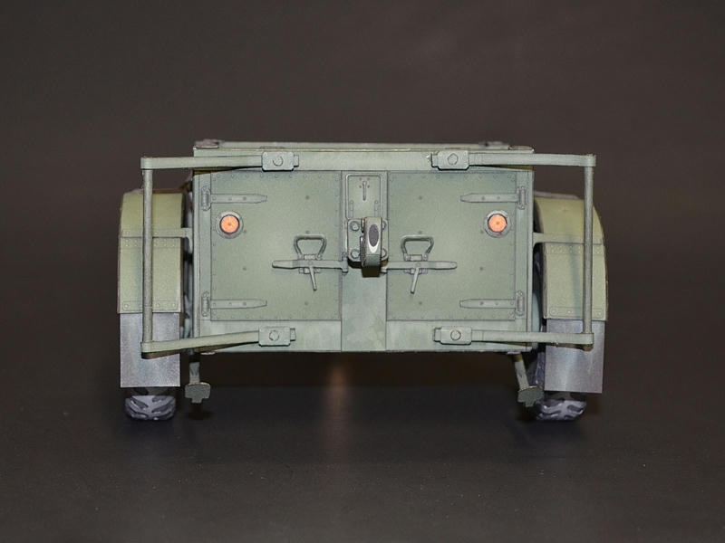 ... And, in hitched position. 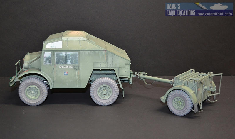 ...
__________________
SUPPORT ME PLEASE: PaperModelShop Or, my models at ecardmodels: Dave'sCardCreations
|
|
#50
09-04-2019, 02:27 PM
|
|||
|
|||
|
Great amount of detail.
|
| Google Adsense |
 |
| Thread Tools | |
| Display Modes | |
|
|


 Linear Mode

