


|
|
|
#1
 05-21-2020, 04:34 PM
|
||||
|
||||
|
X-15A-2 Ablative Heat Shielded - the Mach 6.7 X-15
Heres what I know...
X-15A-2 is aircraft 66671 and is currently parked at the USAF Museum in Dayton Ohio, in its original black finish. Ken West's X-15 model is the same aircraft featuring the lengthened fuselage. The X-15 rocket plane set numerous speed and altitude records back in the 1960s. To achieve higher and faster flight, the aircraft was stripped and coated with a special ablative heat shielding material. The pink coated rocket plane was then painted white (basically because the Test Pilots didn't want to fly in a pink airplane!) This "white" version is the focus of this thread. A-2/66671 made multiple flights to the edge of space and achieved a record speed of Mach 6.7(4520mph) and highest altitude of 67 miles (sub-orbital). 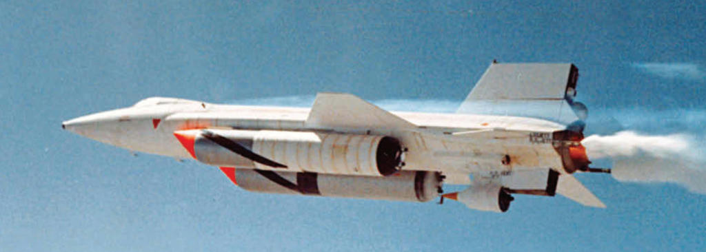 Just getting started on this repaint/remod of Ken West's 1/33 scale X-15A-2 model. Struggling to understand some of the assembly...since I have never personally built the original model. And understanding the assembly of parts is an important factor when trying to recolour the parts! So, I may have to build as I go, to test everything and keep up with understanding the assembly. I'm going to repaint the big fuel tanks too, since they were part of the record setting flights. I haven't decided whether I will bother with the dummy ramjet nose cone that was mounted under the tail fin. It didn't really have anything to do with the record setting flights, other than the fact it was there on one or two flights. However, I will shorten the lower fin as it was. Not sure how fast this project is going to go...I was planning on not doing any big projects this year. Just wanted to focus on Koolwheelz models and not much else. But I need a break from those...so maybe this is it.
__________________
SUPPORT ME PLEASE: PaperModelShop Or, my models at ecardmodels: Dave'sCardCreations 
|
| Google Adsense |
|
#2
05-21-2020, 06:36 PM
|
||||
|
||||
|
Glad to finally see this important vehicle done. That said, I'd still love to see the original -- and shorter -- XLR-11-powered X-15, 66670, with options for its rollout scheme and later markings options for the vertical stabilizer. (X-15 tail markings often differed from mission to mission.)
|
|
#3
05-22-2020, 08:12 PM
|
||||
|
||||
|
Looking forward to see the repaint completed.
Mike
__________________
Cardstock Property Tables and Terms Flying Cardstock Models http://www.papermodelers.com/forum/m...uers-projects/
|
|
#5
05-23-2020, 06:58 AM
|
||||
|
||||
|
So, to anyone who has assembled this model...
looking at the kit, it appears the intended assembly is to build each fuselage section with a bulkhead style former at either end of the skin...and then "butt join each section. First section, for example, has Nose sections #1, #3 and #4, and there are six bulkhead formers for these three sections. I am curious if anyone created tabs or joiner strips for the fuselage skin connections and used only one former at each joint? Or is the butt joint approach ideal?
__________________
SUPPORT ME PLEASE: PaperModelShop Or, my models at ecardmodels: Dave'sCardCreations
|
| Google Adsense |
|
#6
05-23-2020, 08:32 AM
|
||||
|
||||
|
Quote:
|
|
#7
05-25-2020, 11:53 AM
|
||||
|
||||
|
So, I've manged to recolour the first few parts of the kit and I test printed to check my work.
I went ahead and assembled some parts yesterday to see how things look. Just a preliminary test. I decided to stick with the clean white pre-flight look rather than the worn and stripped look of the post flight X15. I'm playing with colours and artwork...I've reduced outline thicknesses and colour to a mid gray. I'm experimenting with the various surface marks and discolourations. The white finish is going to be much less forgiving than the all black look. Part outlines show up a lot worse, seams and connections are more obvious. Any errors or mis-fits are going to stand out a mile! I have limited experience with the double former/butt join method for fuselage sections...and it shows. I tried it years ago on a Marek aircraft kit and didn't like it. I've always built with joiner strips and tabs, so this will take some getting used to. 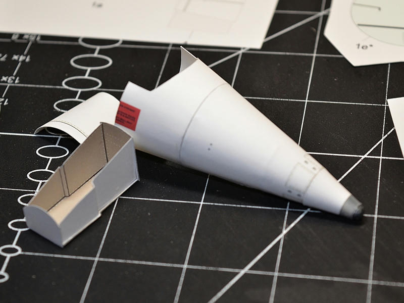 Ken's instruction say to use 110lb cardstock. I thought that was kind of thick...and i don't have any right now...so I used 65lb. Ken suggested .2mm card for the bulkhead formers. Even my cardstock is thicker than that!?...so I was perplexed by that. I used some easy to cut .8mm cardboard. I tried to cut everything very accurately, but my bulkhead formers were too loose fitting... except for the one ahead of the nose gear recess...it ended up being so tight that it caused a ridge in the outer skin. 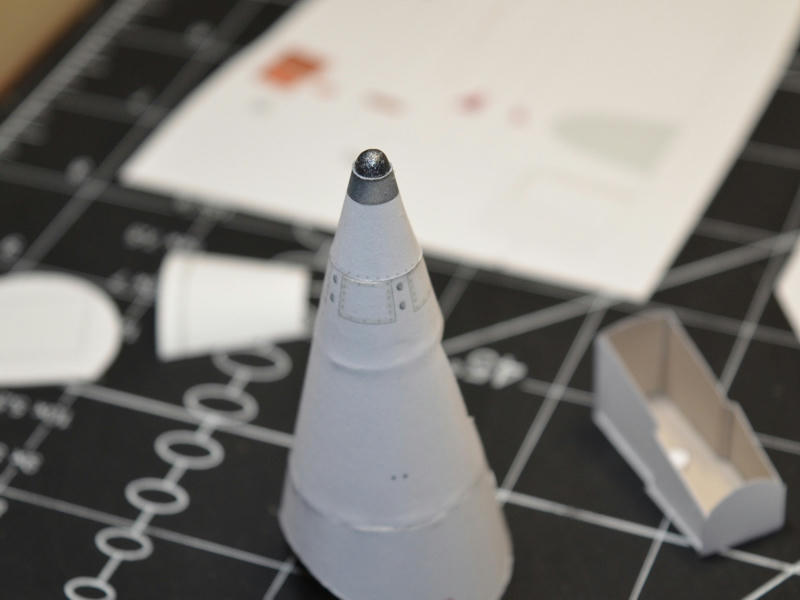 I'm going to have to find some 110lb cardstock and try thinner card for those formers. I might also add some reinforcing strips. I wonder if I should try making tabbed joiner strips for the fuselage sections? I made the nose ball out of a wooden dowel. Just found the right diameter dowel to fit the hole at the end of the nose cone... then sanded it round at the end, then cut it to about 1cm length and glued it into the nose cone. Oh, and I painted it silver, then dry brushed black, then clearcoated it first. 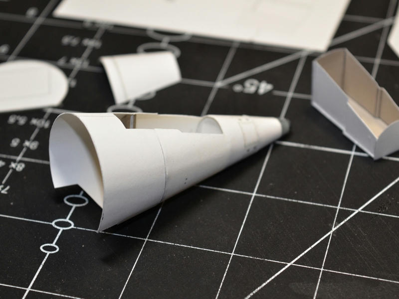 So things are looking okay so far...my build issues notwithstanding. Once I get some more cardstock, I'll try another test build. Don't want to go too far until I've settled on the artwork basics.
__________________
SUPPORT ME PLEASE: PaperModelShop Or, my models at ecardmodels: Dave'sCardCreations Last edited by airdave; 05-25-2020 at 12:30 PM.
|
|
#8
05-25-2020, 02:06 PM
|
||||
|
||||
|
Looks good. Thanks for taking this on.
And, yeah, plain white cardstock can be unforgiving. Cut edges just seem to discolor all on their own. Sometimes, when burnishing parts, I'll lay a piece of wax paper down on my cutting mat so the part won't pick up any dirt. I see why some styrene modelers wear surgical gloves.
|
|
#9
06-14-2020, 11:46 AM
|
||||
|
||||
|
As I mentioned, the double former, butt join method is not my favorite.
This is about the fourth model (of this style of assembly) that I have tried in the last 15 years and this is the fourth time I have been unhappy and disatisfied. I think the biggest issue is the white finish, which makes the seams and joints stand out more than usual, and any imperfections or misalignments of fuselage connections are glaring. I have decided to experiment with tabbed joiner strips...something I am more comfortable with. (I can include these in the kit, and the builder can choose whatever build style they want) Following my usual aircraft fuselage method, I start at the nose...assembly the first section with a simple strip joiner.. then add a full tabbed strip to the rear of the section.... then connect the next (pre-formed/pre-assembled) fuselage section... THEN install a single former into the fuselage positioning it at the seam. Then attach the next section and repeat... 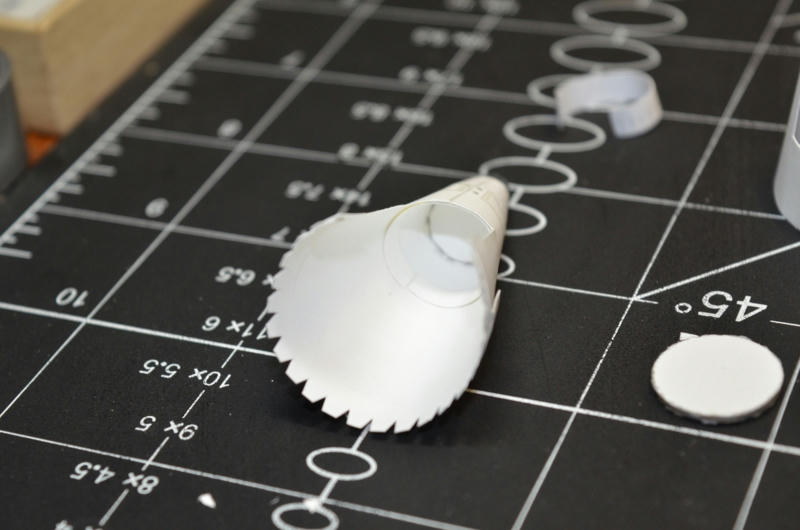 You'll notice an extra inner strip of card in the nose...this is where a former fits. I want to avoid the deformation I experienced on the first build. Fitting the front Wheel Well didn't go easy since it is a bit wider than the cutouts in the bulkhead formers. Not sure why...part of Ken's design I assume. But with some trimming I got it in, and carefully edged glued it into the fuselage. For now I am going to assemble the entire forward fuselage, into the cockpit area, with tabbed joiner strips. I am still considering the rest of the fuselage. 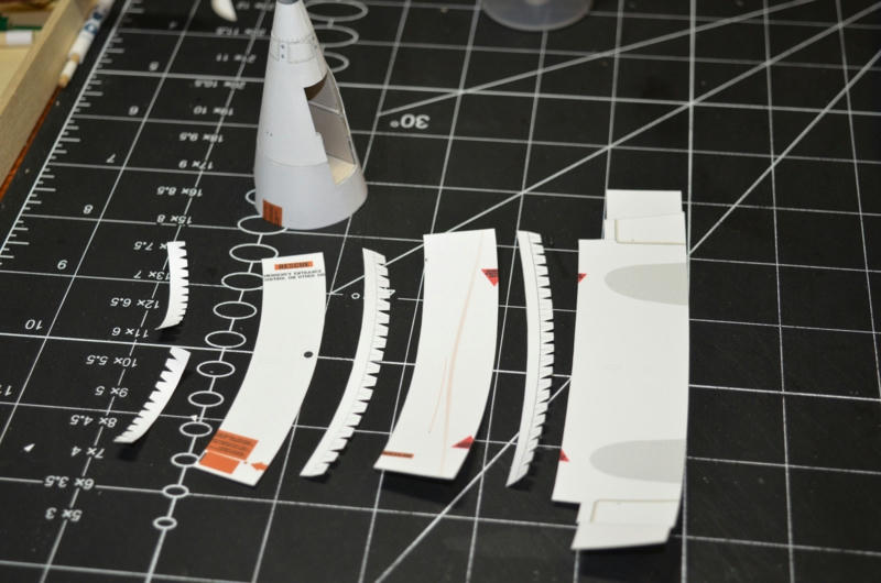 I was a bit confused by the upper(aft cockpit) area and how it all connects, but I understand it now. I had an idea to make some assembly changes in this area, but I decided to go ahead with Ken's method, albeit, I will be only installing single bulkhead formers wherever butt join double formers where intended. I am most happy with the fuselage connections up front...its the best I could hope for with my skills. The joiner strip method helped me immensely. Please note...I allowed the joiner strips to show through in these photos due to back lighting. and I still did not use 110lb cardstock as Ken suggested which would be a bit more opaque. But regardless, once completed, the cardstock will not appear this translucent. 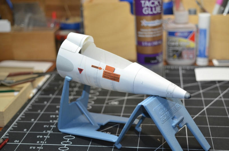 I am not planning on installing the cockpit. I want to build it with canopy closed so you get the full effect of how the white X15 looked. I want it to be tight and streamlined with the closed canopy. But I want to keep the option open to install the cockpit later if possible. Can I do this? Can I come back later and drop in the cockpit with all the bulkheads already in place? 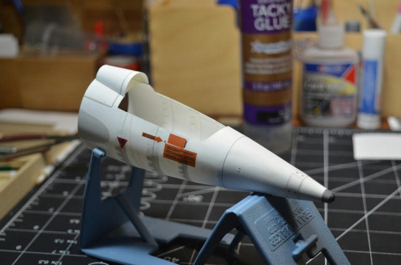
__________________
SUPPORT ME PLEASE: PaperModelShop Or, my models at ecardmodels: Dave'sCardCreations
|
|
#10
06-14-2020, 12:06 PM
|
|||
|
|||
|
Hallo Airdave,
I just see your thread for the first time. I builded Ken West's X-15, too. The cockpit section was most difficult for me. I made a building report. But of course (for me) in german language. Here is the link: https://www.kartonbau.de/forum/thema...5-1-32-fertig/ I hope you can use it. Besides: you made a clean and very good build!
__________________
Friendly PeaceGlue
|
| Google Adsense |
 |
|
|


 Linear Mode

