


|
|
|
#11
 08-29-2014, 02:31 PM
|
|||
|
|||
|
And here's me trying to make something to make 3D instructions less time consuming and you don't like em :(
If you add the time it takes to design, texture, unfold and test build a model using 3D, it takes much longer than that time to make the instructions for it in 3D. You could take pictures, but even then you need to label and explain stuff. I get enjoyment from designing and building models, I don't get enjoymet from selecting, exploding, rendering, labeling model parts. Others seem to be the same, it's mostly down to the time it takes, you could be doing other things. I don't blame anyone for making 'bad' instructions, at least they tried.
__________________
ERM... 
|
|
#12
08-29-2014, 03:29 PM
|
|||
|
|||
|
Then don't be surprised when you don't get pictures of your models built by others, and you see no build threads or worse, incomplete build threads where the builder just gave up and abandoned the build.
__________________
This is a great hobby for the retiree - interesting, time-consuming, rewarding - and about as inexpensive a hobby as you can find. Shamelessly stolen from a post by rockpaperscissor 
|
|
#13
08-29-2014, 04:04 PM
|
||||
|
||||
|
This is all fine and dandy with models that have a small part count.
But try working with a model that has upwards of 2000 parts, resulting in a few hundred "sub-assemblies" and you'll see why some designers resort to the only the three view part placement diagram. Exploded view diagrams, in my opinion, are the best option. You can detail sub-assemblies in this manner, as well as larger collections of sub-assemblies ...and with fewer diagrams. The problem with paper models is that individual parts (of sub-assemblies) also need to be folded, shaped, and attached in a certain way, and this results in more diagrams and explanations. An exploded view diagram of a sub-assembly, will often show you how most parts are to be handled, but its sometimes necessary to add some "sub-sub-assembly" diagrams. Thats when it can get a little cluttered on the page! lol I'm up to page 16 (letter size pages) of Instructions for my centurion Tank. I'm trying to jam as much as possible into the pages, but it still has to be readable. Comprised mostly of exploded view diagrams and sub-assembly placement diagrams, it is taking as much time and work as creating the actual model! Yale speaks the truth. If you can't say it all in the picture, try not to complicate it too much with words. Some things have to be properly explained, but short sentences are necessary. I don't care if the diagrams are hand drawn or pulled from a CAD file, as long as they are understandable. I've seen hand-drawn diagrams that are ridiculously confusing, and yet the designer thinks they are clear as glass. (Maybe to you.. because you designed it! But everyone else is in the dark!) I take photos of assemblies...lots of photos. But I will take a photo of a part, or an assembly, from the precise angle I want to use in the Instructions. And then I use the photo to draw vector diagrams. I draw right on top of the photo in Corel. Add colours and shading, and create 3D models which I can then explode by taking apart the elements, or adding more details. (Since I don't use any CAD or 3D programs, I have little options, so this is the method I have come up with) 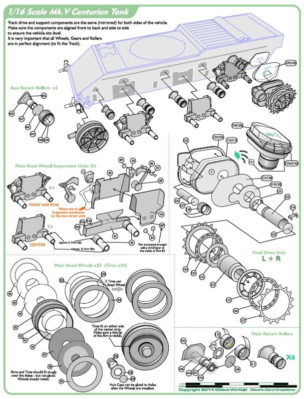
__________________
SUPPORT ME PLEASE: PaperModelShop Or, my models at ecardmodels: Dave'sCardCreations
|
|
#14
08-29-2014, 07:57 PM
|
|||
|
|||
|
I'm glad to see it's not just me who's obsessive about the diagramming of instructions. I find that while creating the instructions is more frustrating, I like that process far more than the design of the model itself oddly enough, which is probably why I spend more time trying to do it justice.
I've made similar posts on this topic, so I'm glad to meet a fellow... instructophile? Here are some references I happened upon in an earlier topic related to this. You can see how I'm currently diagramming my models here. I'm hoping to achieve a mostly text free convention. @airdave: I really like the way you've greyed out the section that is stationary or already assembled, and those drawings look fantastic if you're hand tracing each part. That's just a brutal amount of work. I used to trace the outline of photos of my built models to make the cover pages, and stopped precisely because it was so time consuming. My hat off to you.
|
|
#15
08-29-2014, 09:44 PM
|
||||
|
||||
|
I prefer any illustration to words. Sketches of step by step process is the way to go.
Isaac
__________________
My gallery [http://www.papermodelers.com/gallery...v-r-6&cat=500] Recent builds  Meteor F1, Meteor F8, Mig-Ye8, NA Sabre, A-4E Skyhawk,Mig-15 red, Mig-17 repaint Meteor F1, Meteor F8, Mig-Ye8, NA Sabre, A-4E Skyhawk,Mig-15 red, Mig-17 repaint
|
| Google Adsense |
|
#16
08-29-2014, 09:50 PM
|
||||
|
||||
|
What one must also look at is the type of model that is been designed and the instructions that are been made for the model in question.
Now looking at the model that I am busy working on the instructions and building at the same time is my V12 engine, now this model at the moment is made up of around 5430 + parts, now this engine has parts that will work and move, and one can also make the model a standing model without the parts moving but one still needs to make model as if it will turn to get it to look correct. At the moment I have split the model into about 38 or so major sections that one will build and from there with in those 38 sections are major assemblies that are done to get the model to the point that it looks 100% right. Here is two types of instructions that I have done in the instructions at this point in time to show how to put the engine together. 99% of the instructions that I have done for the engine is using photos with some text to go with it, example below:  The next one that I done is some 3D renders that show parts that need to be put in the correct order for the timing, example below:  The next photo is the part assembly as it is been worked on:  So looking at it in my case there is no right way or wrong way of doing instructions, but one who does go and right the instructions needs to remember that that you are building that model in lets say 2 years time, you are 90% of the time going to have forgotten all the ticks it took to build the model in question. So write my view of instruction writing is as follows "Write your instructions as if you have never seen the model and you need to build it for the first time and there is no help out there to get the model to work."
__________________
Completed Design and Build - V12 Ferrari Engine Current Design and Build - Project S.A.M. Transformer  
|
|
#17
08-30-2014, 01:13 PM
|
|||
|
|||
|
@airdave - you spelt tyres wrong
How does everyone manage the labelling of the parts? Make it up as you go along? start at 1 with the first part you see? toil for hours before inventing a new name for something like 'dangle actuator'? Label the cutting sheets before/after instructions? Prefix sub-assembly parts by a random letter? To me, labelling, and keeping track of what you have labelled is actually the hardest part of making instructions, making the images is relativly easy despite the amount of time it takes. Guess it's down to organisational skills. Any handy tips? Tools?
__________________
ERM...
|
|
#18
08-30-2014, 02:01 PM
|
||||
|
||||
|
Although I would normally argue on the side of correct English pronunciation...
heres what I know... Tyre is actually a variant of Tire, not the other way around. Although Tire is often considered the "american english" pronunciation, "tire" is actually a very old english word ...a derivative of "tir" "tiren" and attire", all words related to dressing a wooden wheel with an iron outer ring and later, a rubber outer ring. So, a solid rubber "tire" seems correct. Even the original air filled "tyre" was referred to as a "pneumatic tire". The spelling t-i-r-e seems to be the correct and most common usage. Actually, if you search my posts and other places, you'll find I use both spellings. It all depends on whom I am talking to (or directing at) and whether I am thinking about it. 
__________________
SUPPORT ME PLEASE: PaperModelShop Or, my models at ecardmodels: Dave'sCardCreations
|
|
#19
08-30-2014, 02:13 PM
|
||||
|
||||
|
Quote:
do you mean numbering the parts? I am numbering parts, in the instruction pages, sequentially... but I am also getting in the habit of leaving some number sets unused. Too many times I find I have missed a part or an entire assembly, and then I have to re-adjust all the numbers to fit the part(s) in. So now, I jump ahead (in numbers) when switching to a different sub-assembly. After the instructions are finished, I then number the parts in the kit based on the numbers in the instructions. Yes, sometimes I put a prefix to a subassembly and then a new set of numbers. This makes it easier to fix that subset if I miss a part or change something.
__________________
SUPPORT ME PLEASE: PaperModelShop Or, my models at ecardmodels: Dave'sCardCreations
|
|
#20
08-30-2014, 03:33 PM
|
||||
|
||||
|
I have always went for the LCID (Lowest Common Intelligence Denominator) when making my instructions...I try to leave nothing to chance and use as few words as possible...
|
| Google Adsense |
 |
|
|


 Linear Mode

