


|
|
|
#11
 05-24-2010, 07:39 PM
|
||||
|
||||
|
Nothing really to show visually today...found some two part plastic putty in the garage that seems to work really well - so well that I could have saved my last tube of Tamiya putty for finer work. This stuff sticks really well to other plastic, well vac plastic for sure and shapes really well to. I think it is quite old as I don't remember buying it so it might have been here when we arrived six years ago...
I did have a bit of a whoopsy last night that has set me back away in the filling and shaping of the wing fillet...the second layer of putty I added last night hadn't gone off by this morning so I had to scrape it all out. It seems the problem is that the hardener for the putty has congealed and what you need for the stuff to set is the gooier stuff that needs to be squeezed out of the bottle and not just the watery fluid that comes out when you tip it - there is a vast difference in hardening effect: whereas last nights had hardly begun to cure, the replacement layer this morning went off as I was shaping it...like, one second it was nice and pliable, the next it was like rock... As I hadn't scraped off the excess, I'm now slowly sanding through the solid mass...the good news is that when it sets it sets like rock all the way through and responds well to 120 grit sandpaper...hope to have the new shape fillets complete and on display here by tomorrow night...
__________________
Please critique my posts honestly i.e. say what you think so I can learn and improve... The World According to Me 
|
|
#12
05-26-2010, 04:22 PM
|
||||
|
||||
|
Variation to technique
All, I use almost the exact same method as SJPONeill to remove parts from a vac sheet. However, I do not leave a 'lip' around the part since this is just extra material for removal. After outlining the part with Sharpie (perm marker) so the ink is on both the part and the sheet (in the "crease" at it were), I score at the part edge, where it intersects the sheet surface. This is done with the blade at a 45 degree angle, two - four light passes is usually enough. Then a bit of "flexing" along the score will cause the plastic to 'snap' along the cut, at the 45 degree angle, leaving just a minor bit of plastic to be removed. Then I use sanding blocks, hasps and sharp blades to remove that triangular section "waste". I hold the part as I do this shaving or sanding, using the marker line to guage how much to take off, stopping when there is the bare hint of 'white' (the plastic color) showing. Then I end with a finer grade of sandpaper on a block to finish it off. I usually to a bit of component dry fit as I go to make sure of the parts fit.
Advantage to this "dry" method (besides being faster) is it avoids the 'flexure' inherent in sanding the entire part on a flat surface - the plastic so thin that uneven pressure is unavoidable, thereby inducing a "wavy" mating surface and fit problems. The older method is from the "day" when vacs were on the small side, so it was easier to apply even pressure when sanding. Even then, wings were a problem, and difficult to hold being so thin and 'flat'. Throw in 'wet sanding' and things were a bit slippery! For wings, I use a sturdy 'scraping blade' to thin the trailing edges as a 'special case' since the amount of material is a bit heavier given the slight angle between the part and the sheet, so less a 'draw' and thicker material results. Hope these comments are useful!
__________________
Regards, Robert In Work: Uhu02 Tinkerbell - [under Tapcho's thread] Tinkerbell - a fairy with an attitude Nobi Junkers SRF BETA build - BETA Build: Nobi's Junkers SRF 1:48 scale
|
|
#13
05-26-2010, 05:21 PM
|
||||
|
||||
|
The main reason I leave the small lip around the edge is that it is a good guide as to when you have sanded enough i.e. when the lip comes free from the part, all the surplus plastic has been removed. I find sometimes that the Mk.1 Eyeometer has difficulty (well, certainly the two that I have been issued...) discerning when the surplus has been removed without the lip as a guide
__________________
Please critique my posts honestly i.e. say what you think so I can learn and improve... The World According to Me
|
|
#14
05-26-2010, 07:16 PM
|
|||
|
|||
|
Great tips! Many years ago I took a ride to the Rosemont Hobby shop in PA and picked up a couple of Roseplane vacs there. Still haven't built them, but this thread may get me going again. The only vac kit I did try to build a Llag-3 and I sanded the fuselage so much the tail curved to the right.:o
|
|
#15
05-26-2010, 07:48 PM
|
||||
|
||||
|
That's OK - if you mount the propeller facing slightly left, it will balance out the tail!!!
Vac forms would still have to be my favourite form of modelling with injection and paper being tied at second place...vacs are as close to scratchbuilding (in terms of using my hands) as I am comfortable getting and some of them are real gems. I haven't seen any of the Roseplane ones but have only heard good things about them...hopefully we will see yours here soon...?
__________________
Please critique my posts honestly i.e. say what you think so I can learn and improve... The World According to Me
|
| Google Adsense |
|
#16
05-26-2010, 08:06 PM
|
||||
|
||||
|
Giving some "lip"
Quote:
This technique is the one I picked up from the Aeroclub folks using their tutorial publication. It can be found on their website (or used to be) at: http://www.aeroclub-models.com/ Site is down right now however because of Peter Wrights' sudden passing, which has hit John Adams pretty hard. Hope they pick up again soon... anyway, thanks for sharing your build (what a monster!) A site with vac tips is on Internet Modeler, using the cut-out technique I've described (though a little confusing, still the images there are just fine illustration) however, he is still using the ol' sanding sheet method of cleaning up the excess - illustrating the problems with holding the parts (note all the tape handles...): http://www.internetmodeler.com/2005/...n/vacuform.php
__________________
Regards, Robert In Work: Uhu02 Tinkerbell - [under Tapcho's thread] Tinkerbell - a fairy with an attitude Nobi Junkers SRF BETA build - BETA Build: Nobi's Junkers SRF 1:48 scale Last edited by rbeach84; 05-26-2010 at 08:22 PM. Reason: Added addt'l resource
|
|
#18
05-28-2010, 04:11 AM
|
||||
|
||||
|
It's all starting to come back now...why this beast has just spent 18 months on the timeout box in the garage..
This problem is that the wing fuselage join is blended more like a B-2 than the quite distinct junction on the actual aircraft...the area shown in red, on the kit is not nearly as acute as it should be 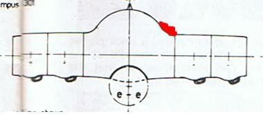 In my first attempt to remove the similarly inaccurate shoulder above the intakes, I sanded too much and ended up with a concave and not convex area. The more filler I poured in the less I was able to get the shape right - it was almost back to the garage for another 18 months but it was raining outside so I postponed the trip to the garage til tomorrow and experimented some more... Rectification attempt #1 saw me use templates from the Dec 84 SMI plans to shape the fuselage spine to closer to the real thing but to do this I might as well have build the section from scratch as the inaccurate base of the spine is too wide and the templates sat too high. Not really wanting a hunchback Vulcan, I've now ripped them out and, following in DV's footsteps from his build at Britmodeller, have used a contour gauge to produce new templates from the kit fuselage to correct the shoulder area above the intakes as much as the molding will allow without doing it all from scratch... 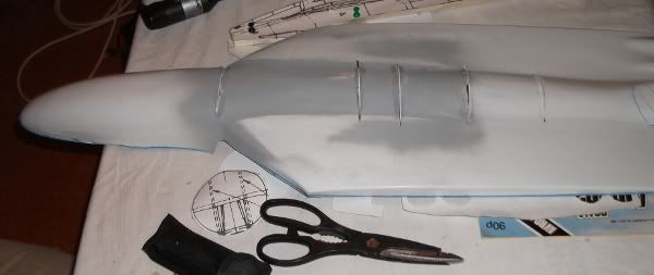 This is my first attempt at placing formers to correct the shape of the Vulcan's spine...I found very quickly that this leads to the slippery path of simply rebuilding the whole fuselage from scratch as the spine is just so wrong as is the way it blends into the forward fuselage. The Vulcan fuselage from the mid=point of the bomb bay to the forward bulkhead of the crew compartment is essentially a simple cylinder and not the slab-sided chunk in the kit...The kit simply does not capture the beautiful subtlety of the Vulcan's curves...imagine Julia Roberts recreated by a chainsaw artist: looks kinda the same but... I've since ripped these formers out and following DV's lead, am using new formers based on the extant spine to rebuild the concave area where I removed the wing/fuselage join shoulder... I've been on the road today, heading down to Massey University to hear COL Martin Dransfield talk about his recent deployment to Afghanistan but will have more pictures and progress over the weekend...
__________________
Please critique my posts honestly i.e. say what you think so I can learn and improve... The World According to Me Last edited by SJPONeill; 05-28-2010 at 04:12 AM. Reason: typo repair
|
|
#19
05-28-2010, 10:25 AM
|
||||
|
||||
|
SJPOneill, I'm not able to see your images right at the moment (I'm at work and they 'block' the external image linkages) but if I understand the issue with the spine, it might be possible to 1) apply a section of sheet plastic as a "bridge", applied from the inside of the part. Then, 2) once this has set, cut out the spine, 'slice it' long ways and remove the extra width and then glue back to the fuselage. Before re-attaching the spine, you would also add another 'layer' of sheet plastic onto the "bridge patch" to get the surface up & even with the rest of the fuselage while giving the spine an better gluing surface without using a bunch of putty to do so... does this make sense?
__________________
Regards, Robert In Work: Uhu02 Tinkerbell - [under Tapcho's thread] Tinkerbell - a fairy with an attitude Nobi Junkers SRF BETA build - BETA Build: Nobi's Junkers SRF 1:48 scale
|
 |
|
|


 Linear Mode

