


|
|
|
#21
 01-19-2011, 07:50 AM
|
|||
|
|||
|
[second post attempt]
Very cool project, thanks for sharing! I've been looking for MSL paper model for years! I even tried to design it from scratch, but it was impossible for me even to render in 3d program the wheels suspensions! I hope you don't mind if I write here some keyword for search engines, like "3d Mars Science Laboratory paper model", "Mars Science Laboratory 3d model", "MSL 3d model", "Curiosity mars rover 3d model"... 

|
|
#22
01-19-2011, 09:25 AM
|
||||
|
||||
|
Keyword as you will (however that works, says the Luddite).
The MSL is up in the downloads here and at the Lower Hudson Valley E-gift shop. The only complex part is the detailed suspension. The key to construction is to study the available pictures and diagrams and dry-fit the parts several times to see how it goes together and gain confidence. The hubs, wheels, and bracket are straightforward. Don't glue up the top pivot or the suspension tubes/connections until you've done a few dry fits and looked at the angles. Make sure you know how it will fit on the main box. You could probably build an asssembly jig from the diagrams on the parts page - or just eyeball it carefully. Yogi
|
|
#23
01-20-2011, 07:51 AM
|
|||
|
|||
|
Some pictures of the built model from above and from sides would be useful to understand if suspensions are correctly mounted.
Does any free 3d software model exist now? It didn't some monhts ago, only pay-ware.
|
|
#24
01-20-2011, 09:15 AM
|
||||
|
||||
|
This is one side of the suspension photographed from the side and top. Not attached to the body, but as long as you attach the suspension to the sides in such a way that the body is level, it will be correct. Bear in mind that the tubes are NOT secured with glue yet, as Yogi suggested. The angles may be slightly off in this respect, but it's very close to final shape.
(Also, ignore my spoke orientation -- I managed to attach the wheels with the spokes misaligned and never got around to pulling them off and reattaching them oriented in the same direction. Mostly because I was worried about destroying something in the process.) 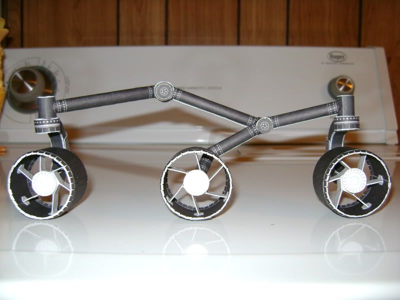 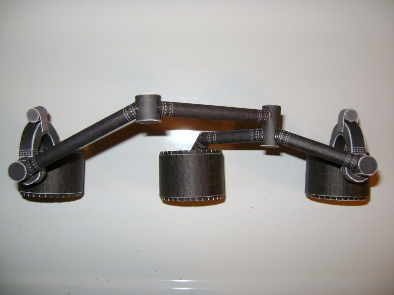
|
|
#25
01-29-2011, 02:28 PM
|
|||
|
|||
|
Thank your for pictures, I tried just today to build a suspension, and it would be impossible without these pictures...
Do you think they'll be able to carry the weight of the whole reover? Once built they look much more fragile than they do in picture! I think I'll give try to build them in wood, using paper version just as a model. BTW, I think you forgot something in the model version I downloaded: joints of the various parts of each suspension (the small cilinders with holes) can't be properly glued, due to missing "wings" (I don't know the proper english name, please look at the picture). 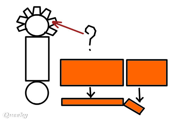 I also think the central parts of the suspension could be built more easily if rods 2 and 3 where already joined together on the paper, without needing to glue them together (you'll have just to cover the hole in the joint using a small paper triangle - Please look at the red rectangles in the picture).
|
| Google Adsense |
|
#26
01-29-2011, 10:29 PM
|
||||
|
||||
|
MSL Suspension
jumpjack,
The suspension will hold the weight of the rover - standing for display. If you intend to "drive it around" a lot it probably won't last long. Gluing the suspension tubes into the connecting cylinders makes a plenty strong and rigid joint.    simple flat suspension and complex suspension assembly prototypes The suspension connections (cylinders) don't have tabs (wings) as the ends are not structural, so just put a little (very little) glue around the edge of the cylinder and close the end cap over it. Using tabs forces the edge out of round (makes a polygon with as many sides as the number of tabs). The suspension connections are very visible on the model - so I decided to leave them as round and smooth as possible. You can draw in tabs by hand if you want to use them.   I've looked at making fewer pieces to the suspension to avoid the need to align (or jig) the tubes - it can be done if you make the suspension "tubes" square but I didn't like that look. So the intent is: cut the parts, roll the tubes and cylinders; edge-glue the caps down on the connectors; dry fit the parts and align them using the drawings and pictures; then glue them up. You could just roll one long tube, cut the ends at the proper angles, and glue them together. I didn't do this as the joints are angled both horizontally and vertically (bend down and splay outward) - easier to dry fit, adjust, and glue. Of course, the basic tenet here is: if you see a better way to build it, by all means do so and let us know. Always up for making it better and/or easier to build. Yogi
|
|
#27
01-30-2011, 02:13 AM
|
|||
|
|||
|
Quote:
 Quote:
 Then, when you connect rod 2 to the connection, by properly rotating it around its axis you'll get the right angle for rod 3 too. It's quite hard to draw it: 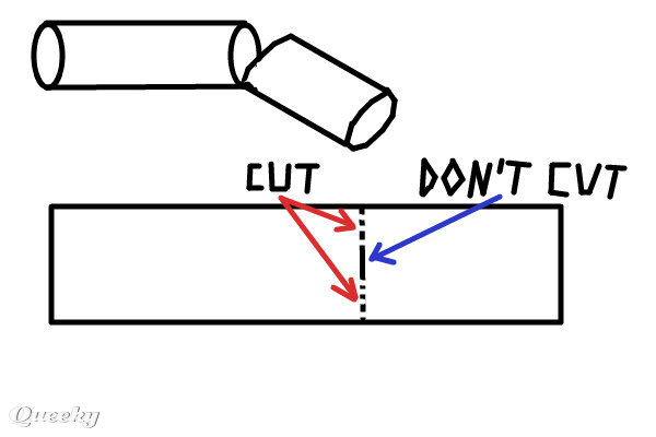
|
|
#29
01-30-2011, 06:30 AM
|
||||
|
||||
|
jumpjack,
I understand what you're doing with the tube. Might actually work as well to size the part based on the outside length, slit the tube on the bottom, and let the short piece slip inside the longer piece as it folds. You could use the overlap for gluing and avoid adding in the "wedge" to cover the gap. I didn't do it that way as I would have felt the need to provide the correct angle on the part - which would have required building a few test pieces to trim, fit, and measure (just laziness on my part). The piece does lie flat, but when working from a three-view (top-bottom, fore-aft, sides) the part is angled. Using the connecting cylinder as a reference: connector is square to the main body; aft bogie suspension tube angles out away from the body; mid bogie long suspension tube runs parallel to the body angled down; and the remaining short tube bends further down and outward (away from the body) to reach the hub inside the wheel. I really was too lazy to try and figure out all those angles and rotations, then curve the tubes' ends to make the connections. Seemed they'd need fitting anyway so I opted for the cut-to-fit method. When I build these I work from the diagrams in the pattern, set the parts over the side-view drawing and mark one cut angle, then set the parts over the top-view diagram and mark the other angle. Connect with a light pencil line, eyeball the fit, look at it again, then cut and assemble (repeating if I screw it up). You could simply trim down the provided parts, glue a rolled paper cylinder inside to connect them, then recut the combined part. Yogi (it is "quite hard to draw") Last edited by Retired_for_now; 01-30-2011 at 06:50 AM.
|
|
#30
01-31-2011, 01:52 AM
|
|||
|
|||
|
Quote:
I wonder if any freeware programs like Pepakura Designer do exist.  Once you have a 3d module, it should be quite easy to get an "unfolded flat versione" of it using such a SW. Once you have a 3d module, it should be quite easy to get an "unfolded flat versione" of it using such a SW.
|
| Google Adsense |
 |
|
|


 Linear Mode

