


|
|
|
#591
 06-07-2011, 05:20 AM
|
||||
|
||||
|
More WIP shots
So my first successful PMA! I think this was my 6th attempt to build one. The key to it was the super solid black card I used (clearly visible in the second pic below). It is the same stuff picture framers glue photos on to, so it is designed to stay flat.
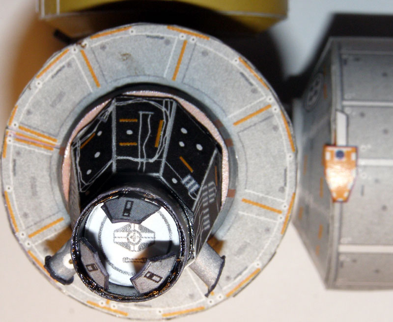 In the next pic, you can see why I needed such a hard flat surface: where the excess white paper is, is where that fold line will not glue down onto the surface, leaving a gap - which got flogged to death with the probing, before admitting defeat. I'll blacken it with a sharpie before mounting. 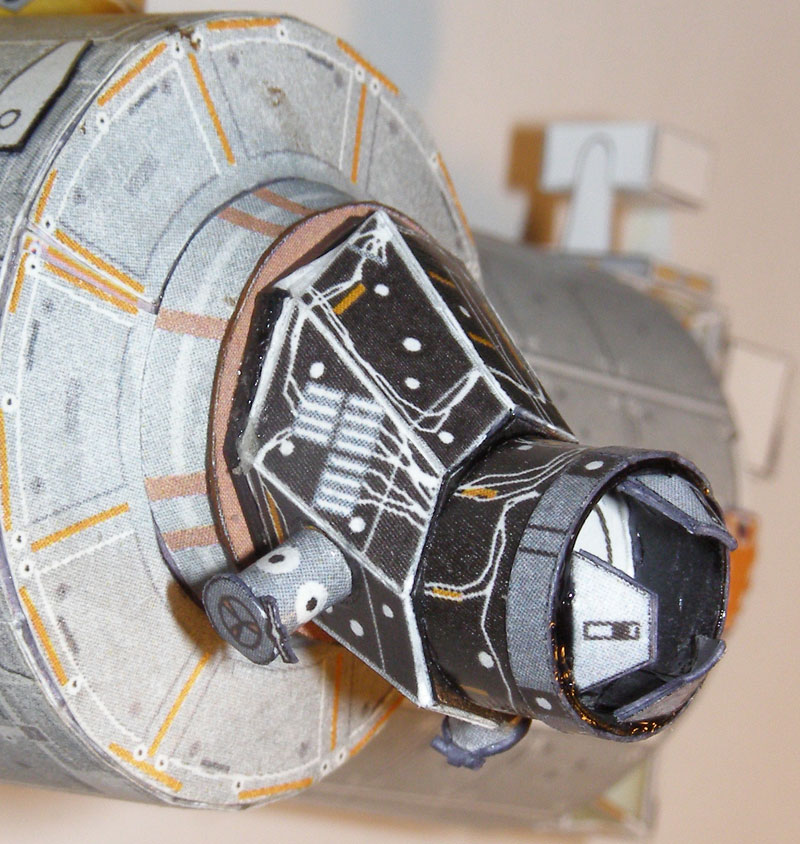 This PMA is for display on the station and won't have anything docked to it, hence the completion of the docking mechanism. The one my orbiter docks to will have a for-real docking adapter, made with a shaft and magnet combo. Do you get the idea I loved magnets as a kid. Hell, when I was growing up - if it had magnets, it was awesome.  Seeing these up close, it's far more detail than my eyes can make out when I'm making the things - and I wear +2.25 glasses for modelling! All the flaws are really obvious. Ah well, they look pretty good at arm's length. The good news is that the rads have been in the same position for some time now, in their final places, and if they have drooped, it's by less than I can measure: 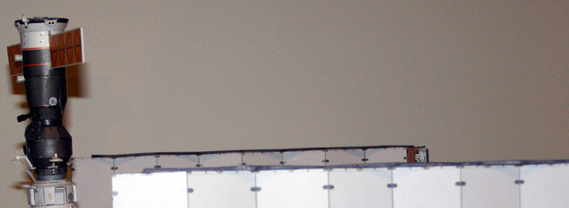 I'm happy about that. Before I started doing my Kibo rebuild, I looked at all the mistakes I made with the original, and cut the thing into 4 bits. It wasn't easy - that thing was waaaaay over-built, with 4 and sometimes five layers of very thick paper internally reinforcing it. I was nuts. I'll post some pics of the Kibo rebuild soon.
__________________
How many escape pods are there? NONE, SIR! You counted them? TWICE, SIR! 
|
|
#593
06-07-2011, 07:46 PM
|
|||
|
|||
|
These deserve to be posted here. The only pictures ever of the ISS with the shuttle attached.
The Soyuz "Flyabout" Picture Update Thread
__________________
Check out these awesome REAL Space websites! AXM: http://axmpaperspacescalemodels.com NSF: http://nasaspaceflight.com SSM-2007:http://space-shuttle-mission.com
|
|
#594
06-08-2011, 02:29 AM
|
||||
|
||||
|
I THINK I MAY BE IN HEAVEN.
Here's the full gallery, with all the hi-res images: NASA - Expedition 27 Departure Photos
__________________
How many escape pods are there? NONE, SIR! You counted them? TWICE, SIR!
|
|
#596
06-12-2011, 04:29 PM
|
||||
|
||||
|
Kibo Rebuild
I have completed my new Kibo. Because I made so many mistakes the first time round, I wanted to do a much better job than I did originally, and I managed to achieve that, while making some completely new mistakes! Here's my story of trying to get Kibo right - because it is not an easy module to make.
Firstly, I always want to start with a perfect tube to begin with - that's the key to any module. I have abandoned white glue (I normally use plain old PVA) in favour of a gluestick for gluing tubes and cones. It allows easy placement, lots of initial movement without springing open, and the results are outstanding. Plus, I use the Gluestick itself to roll the tube before gluing. 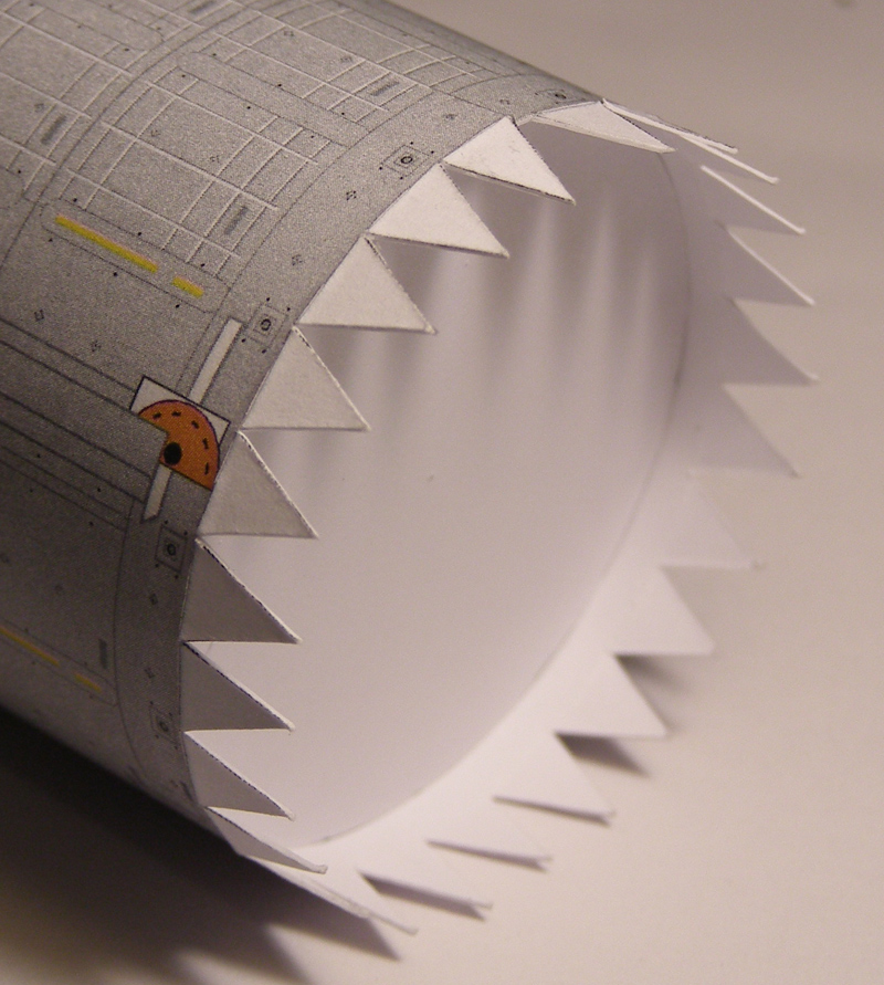 Because the tube itself has to be perfectly round for the end plates to fit correctly, I always reinforce the ends - and in Kibo's case, also the middle as well, with painstakingly cut out circles of 400 gram paper. I use a dial compass to mark them out and cut them carefully. I start at half a millimetre radius smaller than the end-plate size (43.5 mm diameter; 21.75 mm radius) and work my way downwards until a disc fits perfectly inside the tube. I have found that it is silly to force a too-large disc into a tube as it deforms the shape of the tube. It is a laborious task, but the end results are worth it. I remembered how hard it was to keep the original face of Kibo flat, so I reinforced the new face as well. I avoid gluing right to the edges of the face plate, so as not to make a thick connection showing lots of paper depth when the front plate is fitted. 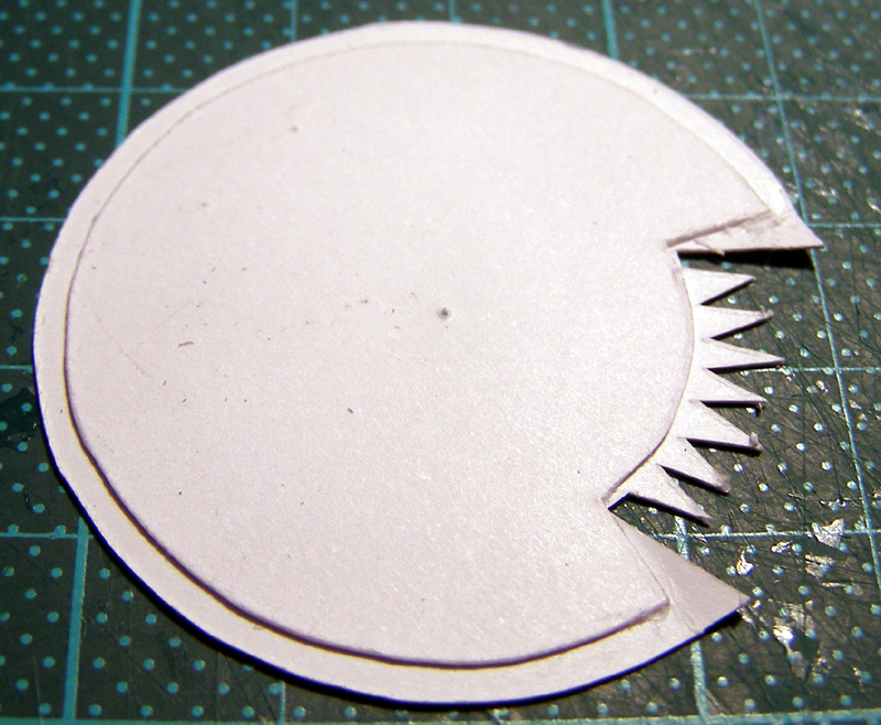 Once the circular reinforcing glue has dried, I glue on the end cone which forms the base of the CBM docking ring. I roll the end cone part around a pen, keeping the edge perpendicular to the pen at all times. This is the best way I have found to roll a cone shape. Just vary the diameter to the object you roll around, to change the diameter of the cone. 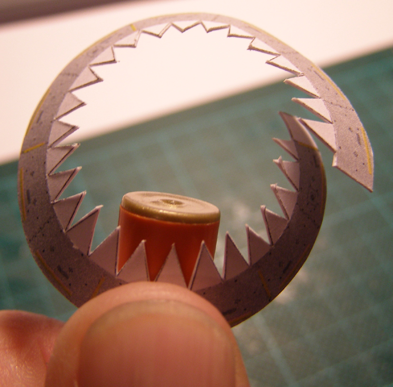 Then I glue the end-cone in place. Sadly, I made a mistake here. 400 gram paper glued in place - as a base for the docking ring - is not rigid enough to support the weight of my kibo, with its brass parts. Your results may vary. I now have to glue a strip from Node 2 to Kibo to stop the cantilever deflecting by about 2 degrees. :( 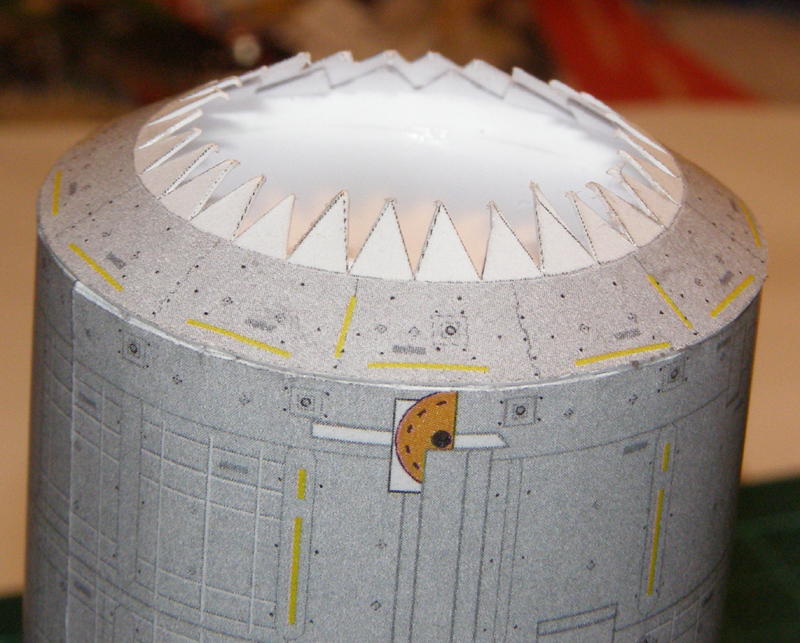 Around to the front of Kibo now... before I fit it, I cut a hole in the reinforcing front plate. This allows the brass tube which extends from the JEF, to perfectly plug into Kibo. I have marked the center line so it's located correctly.  Then I very carefully cut a hole in the front plate of Kibo and a small part of the angled recess so that my robot arm support can be located correctly. It's just several layers of paper cut into a wedge, then glue in place. It goes right through the reinforcing plate too - so there's plenty of glue to hold it in place when complete... Then I glue the front face on, and use my small metal ruler to flatten and secure it to ensure it does not go concave. This can take a few minutes, until I am happy the glue has gone off. 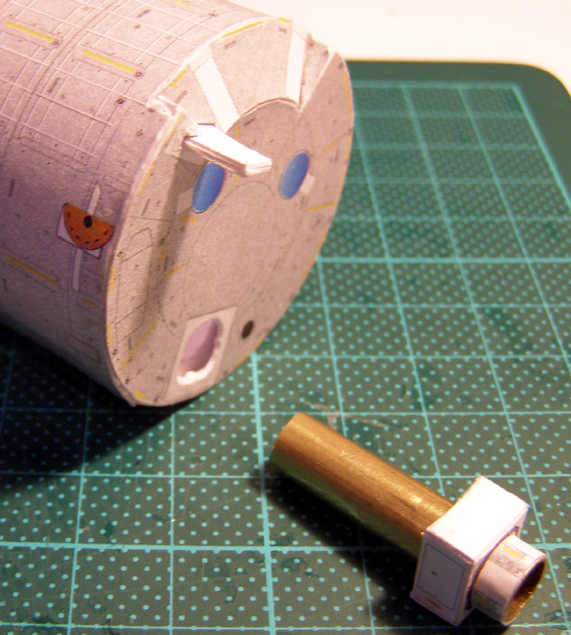 Creating a nice symmetrical airlock stymied me last time round, so I took great care this time. I think it came out ok: 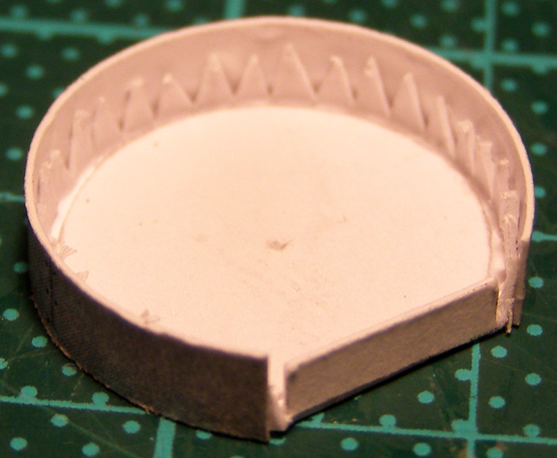 Time to take a look at the new kibo and the old, side by side. The old one is a bit mangled due to me cutting it up. Here you can clearly see the diameter difference of the original Kibo module. This one is 100% correct diameter (44mm) as measured by my vernier calipers - so ot matches all the other shuttle-delivered parts. 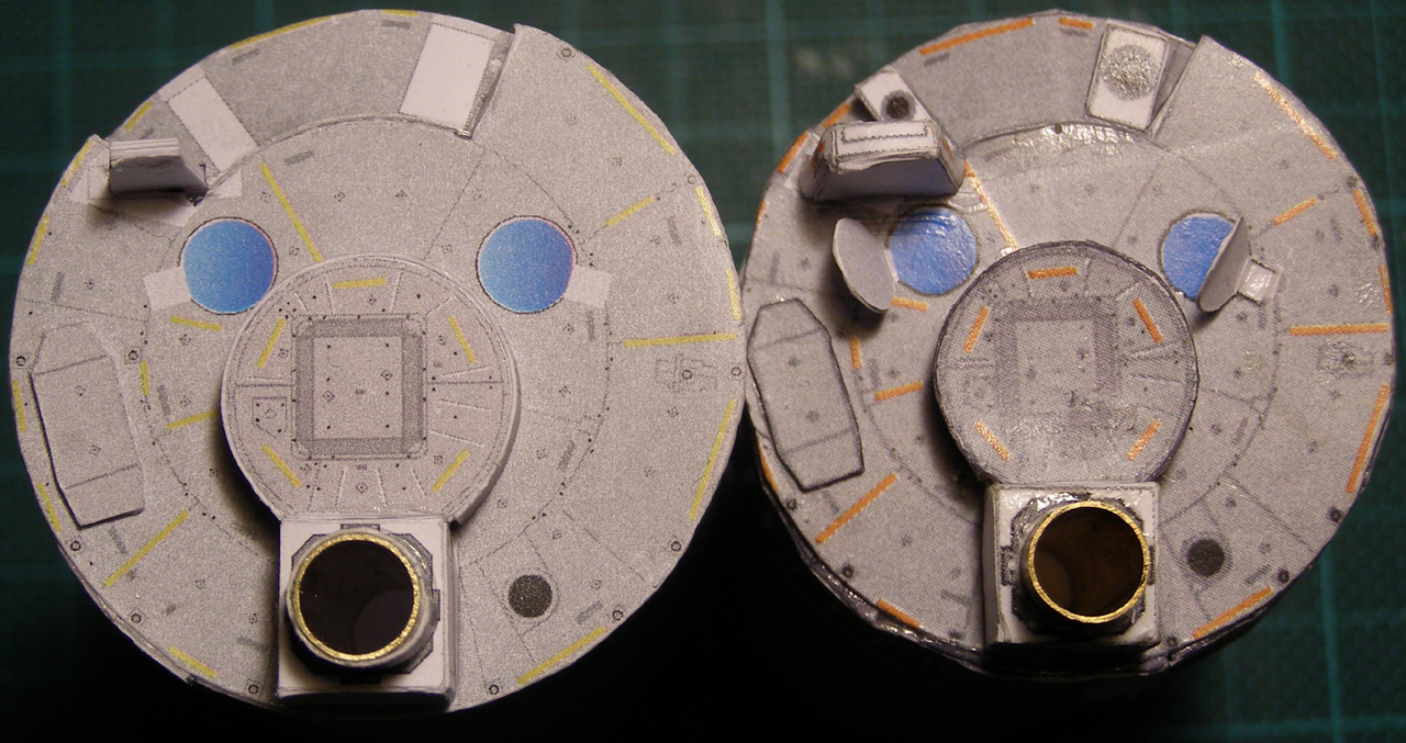 Naturally, I always reinforce my docking rings too. But most importantly, I glue in a circular insert. I find I can't ever get anything even remotely circular unless it's got a circle in it. I hope that makes sense. :P 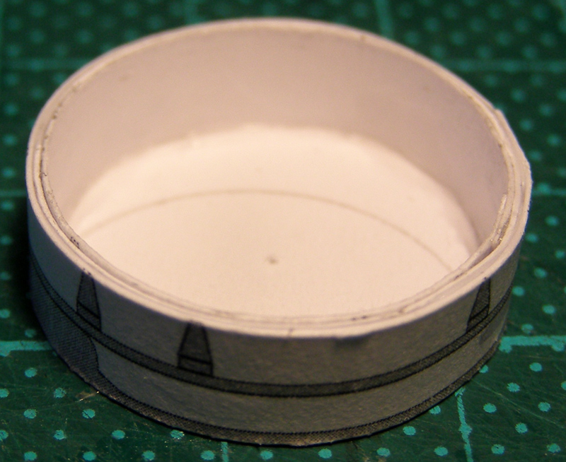 Below is the end plate which ended up being a flop. Note to self, strong where it needs to be, and SOLID where it needs to be. I should have used the photograph mounting board as circularizer an end plate mount point. 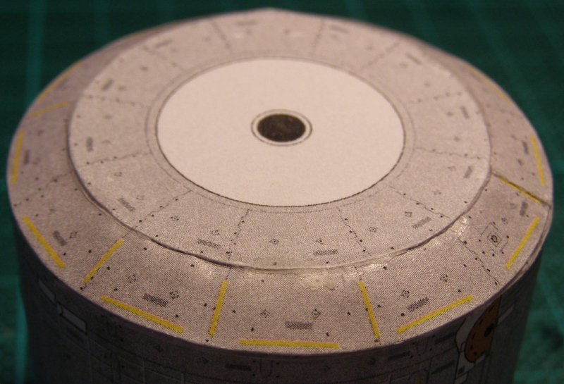 At least it looks OK. Got half of it right. Then I test fit the docking ring of JEM into the hole of Kibo. I have learned the hard way that it is very easy to make a part fit into a hole, than it is to enlarge a hole for a part. 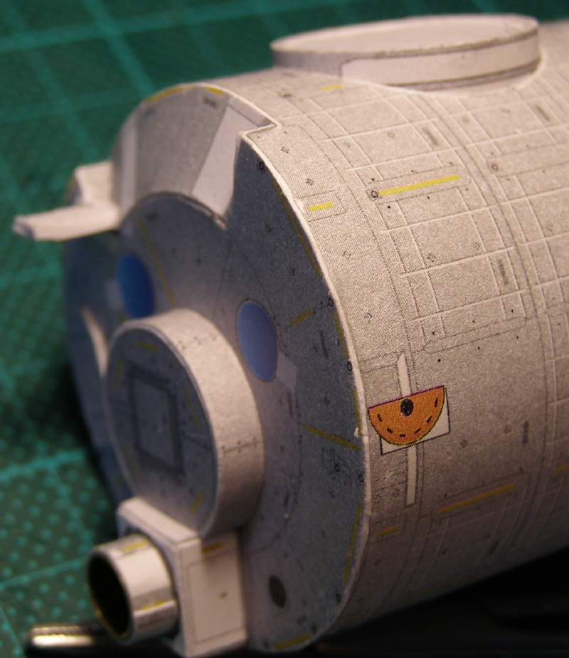 Here you can see the docking ring fits perfectly, the front face is flat as a pancake, the airlock fits beautifully, and that the face is joined to the body of Kibo nicely, with no indication it's reinforced so strongly. I also ensure the top face of the JEM is nicely flat too, because this is also a challenge. The lower side is reinforced in exactly the same way as the front of Kibo is. 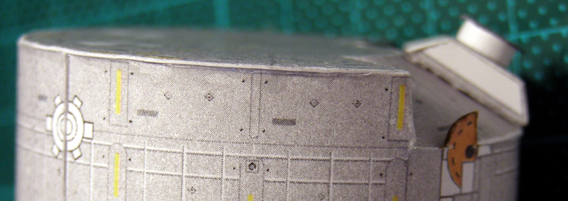 Finally, I can test fit Kibo to Node 2, to make sure it all works as intended... 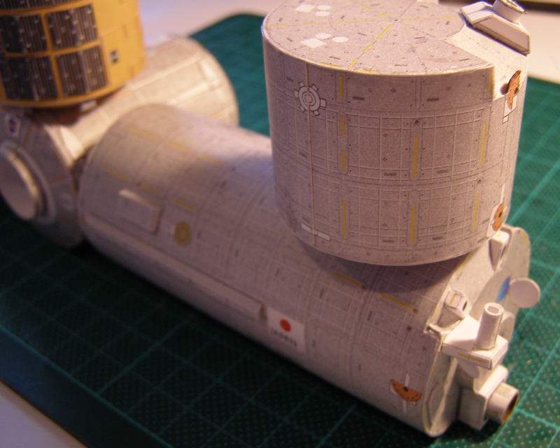 One of the trickiest little jobs of Kibo is to get the long straight panels on the side correct. To get this right, I first bend and glue the interior of the parts, and force them into the correct shape as the glue dries, using two metal rulers to hold them in place. Once the glue dries, they are quite stiff for tiny parts. I then glue a stripe of 400 gram paper inside them, to give me something to glue them down with. Ilet the glue go off a little before gently mounting them in place. 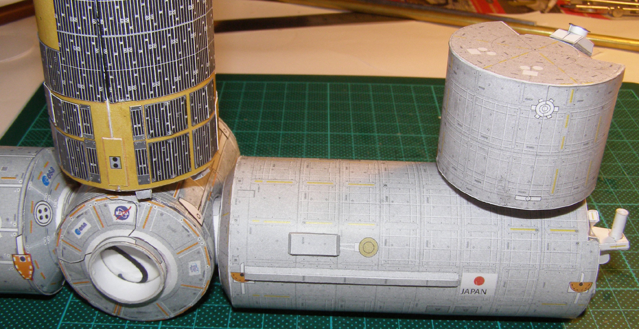 So, now it's on the S3 and P3, and putting it all together. More photos and the movie, coming soon!
__________________
How many escape pods are there? NONE, SIR! You counted them? TWICE, SIR!
|
|
#597
06-12-2011, 04:39 PM
|
||||
|
||||
|
You did a painstakingly good job in getting everything righter than right. I really like how you reinforced the pars and the careful cutting.
There's just one thing I just have to ask you: why, for the main cylinder, did you not use a flush connection with an inner glue strip instead of the overlapping one you have now? With so much careful measuring I at least had expected that, because it just makes the seam look even more hidden. (I just notice the number of my posts. This one marks the 666th. I didn't mean to be evil, though....)
|
|
#598
06-12-2011, 05:52 PM
|
||||
|
||||
|
Thanks! But, it's not so much painstaking, as simply trying to get it right the second time around. I do not want to do a third Kibo! It's the cutting of circles which is the real critical part of the job I think. If you get that right then the rest is pretty straight forward.
Cutting the circles is something I wish I could do better and faster, because it's already cheap (No pun intended; NASA). The problem is that cutting through 400 gram paper with a single circular cut is not at all easy. I often have to cut 2 or 3 circles before one fits correctly. Then I have the size right to cut the other three - if I'm lucky. Quote:
The other aspect of the internal join is that it is very difficult to get the radius right at the join site. Typically, you have to wait for one join to set before making the other, and this can easily result in a reinforced part of the cylinder being rigidly held in the wrong radius. There's nothing you can do to circularize it once that happens. Over all, I think I'd rather have a near-perfect cylinder with an overlap joint, than one with a smooth joint which causes the cylinder shape to deviate from circular, as this affects the way the end plates join to the body, and hence the overall appearance of the module.
__________________
How many escape pods are there? NONE, SIR! You counted them? TWICE, SIR! Last edited by Mobius; 06-12-2011 at 06:14 PM.
|
|
#599
06-12-2011, 06:07 PM
|
||||
|
||||
|
Another way of using an inner join is to cut out a second - inner - cylinder, just a tiny bit smaller than the outer one and glue it to the inside of the outer cylinder. Make sure you start halfway the outer cylinder so that the seam of the inner cylinder and the outer one are opposite eachother.
Immediately start to roll it to keep the cylindrical shape. testfit the ends make them join and if necessary, cut off some of the inner tube to let the outer one touch its ends. When the shape is nice and circular, join the ends with some more glue. Immediate reinforcement and no seams.
|
 |
|
|


 Linear Mode

