


|
|
|
#1
 08-13-2012, 03:07 PM
|
||||
|
||||
|
Delta IV Heavy 1/96
So, I started on Mark Cable's Delta IV Heavy. First of all I have to say the design looks great. A lot of attention to texture, valves and tubing. I really enjoy Mark's meticulous research for the right shapes and colours.
While building, it slowly dawned on me how big this rocket is. It's enormous! The cross section already is much larger than the Atlas V and its engines are BIG! Wow. I printed the orange insulation foam sections on textured ribbed sheets of white paper to get more effect. The other parts were printed on satin gloss photo paper, Together this looks awesome! I also used some metal wires for the tubing alongside the hull and fuel line. This part has become beautifully realistic this way. But I also think a rocket this big with such a length really could do with a couple of reinforcement rings inside. Even when built in 200 gram paper as I usually do, this one really gets too weak. I already used eight or so in this whole length. The engine section is an ingeniously designed piece. It goes together like a charm. I only did not wait until I glued the tapered section to the cylindrical section with cutting out the curved shapes. I did that right after the part was dry. This was also because I strengthened the engine section with two reinforcement circles, so if I glued it together I would have had to do some difficult cutting. The engine is very nicely shaped, just like the Titan ones. I had to adjust the upper half a tiny little bit and cut off 1 to 1,5 mm to get it fit tightly on to the lower section, but that is just a minor adjustment. The metallic shielding however is a bit of a mystery. I had do look at several pictures to see how it should go on and it just didn't fit right. The upper band does not go all the way round and that is confusing. The drawing is also not a good guide in this one. And a very minor issue is the fact the part is named A18 in the parts and A13 in the instructions. The connection part of the engine bell to the tail section is also a bit of a puzzle, since the circle (part no. A8) not exactly fits on top of the tapered ring (part no. A12). It needs some serious trimming and I want to do that part again with some scratch building added. And as we are on the numbering: part A11 in the instructions is called A 12 at the parts sheet and I still need to figure out how exactly the part has to be attached to the wall of the rocket. The accompanying photos do not make this clear. But above all, I like the design, I love the size and shapes in this kit and It will be a real looker on the shelf when finished! 
|
| Google Adsense |
|
#3
08-15-2012, 05:46 AM
|
||||
|
||||
|
I have finished the central booster, apart from the harmonica bits, which still puzzle me a bit. I will find out how they have to be made, I guess.
The engine bit was a little tweaked, I used a circular bit on both sides of the small tapered section the engine is glued to and made a hole in the smaller one. I lengthened the upper part of the engine a little bit so I could shove it in that hole, and then I used my shelves and a rubber band to get the engine bell perpendicular underneath the rocket. It worked and the booster can stand straight on its own engine. I am happy. Now two more to go. Apart from the aforementioned small things, this again is a great kit from mr. Cable. I think it looks awesome and already is very impressive next to all the other ones on my shelves.
|
|
#4
08-15-2012, 07:26 AM
|
|||
|
|||
|
Excellent model so far. I haven't started the Heavy yet, although I did build the Medium. It was a straight stock build except for lots of internal reinforcing rings (give it a really nice, perfectly round shape in addition to strength) and a magnet glued inside to attach to a stand.
I do like the tape for the engine nozzle shielding. I used the stock part-it came out ok, but I think the tape looks much better and will try using it when I build the Heavy. The Medium is an excellent kit also and I highly recommend it. Thanks, erik
|
|
#5
08-15-2012, 08:20 AM
|
||||
|
||||
|
Fine build, as always. I scratched a Delta IV Medium (5,4) and a Delta IV Heavy some years back; I'll have to give these new ones a try sometime. You've built a mighty fine-looking launch vehicle.
One quibble, though. And I'll qualify this by saying that if you've got more up-to-date information, I will gladly stand corrected, but I question the RS-68 colors. Back in '09, some of us on the Yahoo space modeling group were discussing the issue; there were photos of RS-68 nozzles that were white, photos where they appeared black, photos where they seemed to be a shuttle ET orange and pics that showed the black-and-silver pattern you've modeled. I figured I'd just go to the horse's mouth so I emailed Rocketdyne and asked about the color of the nozzle, and here is the reply I got: "Thanks for your question. Current flight nozzles for the RS-68 are black on the outer surface, due to the Thermal Protection System (TPS), which is a coating. The coating does cover a thin cork layer on the outside of the nozzle. Nozzles are an amber color on the inside of the nozzle before firing, and dark gray after firing. A few nozzles early in the RS-68 program were painted white. Also, some nozzles used only during ground test do not have the TPS coating and would appear brown in color." Granted, that is from 2009 and there have been several Delta IV flights since then, and if you've got more timely info, I'm glad to be corrected.
|
| Google Adsense |
|
#6
08-15-2012, 08:53 AM
|
||||
|
||||
|
Nice info, David. I have painted the outside of the nozzle antracite, because I prefer that in this scale to black. I like to leave the silver shielding on because it gives the engine a good look. It indeed is very hard to obtain good close-up detailed images of Delta IV rockets. The engines often are hidden while on the launch pad and hard to see when transported.
Included are some images I found on the web:  Brown, fully uncovered, those pipelines along the nozzle might be covered with that silver shielding, according to their position.  Apparently an image from 2000, black nozzle, silver shielding of tubes. White engine bell, no pipelines.  white engine bell, different shielding pattern. 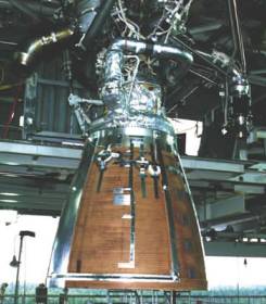 Brown with shielding 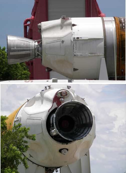 And a test object called the SFU, Static Fire Unit, now displayed at the Air Force Space Museum in the US. Perhaps a bit weathered but a good view on the engine. This one is left probably without any ablative protection to better show the actual engine. I guess this shielding is the shape Mark has been using for his kit. I guess nowadays it is black(ish) outside with the silver coloured shielding.
|
|
#7
08-15-2012, 11:33 AM
|
||||
|
||||
|
Wow, this is a big thing. Looks great and thank you for the pictures of the engines.
|
|
#8
08-17-2012, 05:50 AM
|
|||
|
|||
|
Quote:
Great job. I especially love seeing people superdetail their kits. makes me a happy designer! And about those rocket nozzles... yeah, I had an awful time figuring out the color and markings. I have found no clear pictures of an operational delta with an image of the engine without the protective covers. I had it narrowed down to the brown with cladding on the DIV at the museum, and black. I found a few launch shots that appeared to be brown, but I was still concerned that was just the light from the exhaust blowing out the color on the image. In the end I went with the museum DIV because it was the only clear shot of the engine bell, but I still felt there was a very good chance they were black, possibly with less cladding.
|
|
#9
08-17-2012, 06:42 AM
|
||||
|
||||
|
Hi Mark, nice you joined in!
yes, I meant B12 but I solved it by looking at the very undetailed pictures of the Delta on the pad and concluded it was a kind of bumper block sort -of - thing. I made it from mat paper. Looks quite allright, imho. (it is called B11 on the core booster instructions btw) Some more questions now (-; - What's A17 for? it is not mentioned in the assembly instructions. - How are A 15 and 16 formed exactly? Do I need to fold over the straight white part and glue it to the blue area? Glue the two pointed parts together? Fold the triangular part on the bottom into a more or less cone-like shape? - Where is part D5? And would it have been useful? (-; - On the sheet with the delta's 2nd stage there are two parts called D2 that look very different to the parts called D2 on the instructions of the core booster (the thin strips over the fairing). I guess they are D4 on the core booster instruction drawing. I really like this one. It is a big rocket and it already looks cool even though it isn't finished yet. Last edited by Paper Kosmonaut; 08-17-2012 at 06:48 AM. Reason: pressed publish too soon. i had to add some words and letters.
|
|
#10
08-17-2012, 08:20 AM
|
||||
|
||||
|
This is what I made from A15/A16. I added a 3 times laminated piece of card between the pointed parts and folded them toward each other at their roots. Over the top I glued a small strip of paper to close the seam. The aft end was curved and glued. I think this is close to what the real thing looks, at least the SFU at the Air Force Space Museum looks like this.
Oh yeah, before I forget, there still are two blue surfaces on the tapered end of the engine section. Is that where A17 should go?
|
| Google Adsense |
 |
|
|


 Linear Mode

