


|
|
|
#1161
 09-03-2016, 08:26 PM
|
|||
|
|||
|
I like the way you made the pipe adjustable before so you can make final adjustments before gluing. It led to a "Now why didn't I think of that!" moment.
__________________
This is a great hobby for the retiree - interesting, time-consuming, rewarding - and about as inexpensive a hobby as you can find. Shamelessly stolen from a post by rockpaperscissor 

|
|
#1162
09-04-2016, 12:39 AM
|
||||
|
||||
|
Thanks for watching elliott,
yep, and this has actually paid for itself well.  And these plugged together strand I've tried on on the MLP, initially with the dummy TSM, because this is much simpler than with the unhandy real TSM. And lo and behold, a slight shortening of the intermediate piece (Ø 2,5 mm) was necessary actually, 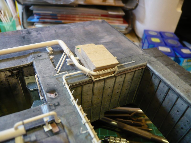 so that the nozzle tube just so fits around the TSM corner and does not protrude too far.  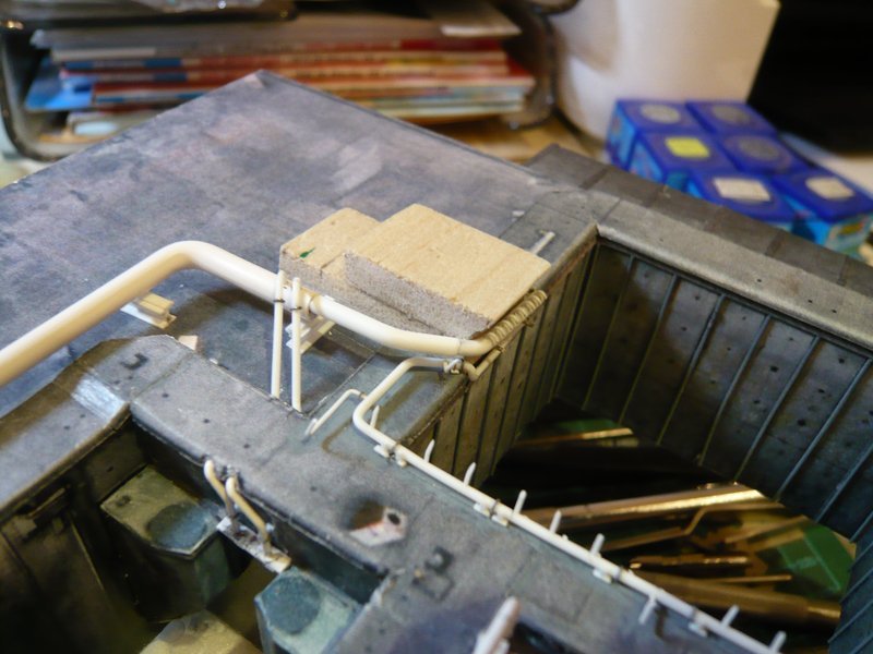 But the acid test came then with the real TSM, and as I had feared, it was really quite closely at the corner, 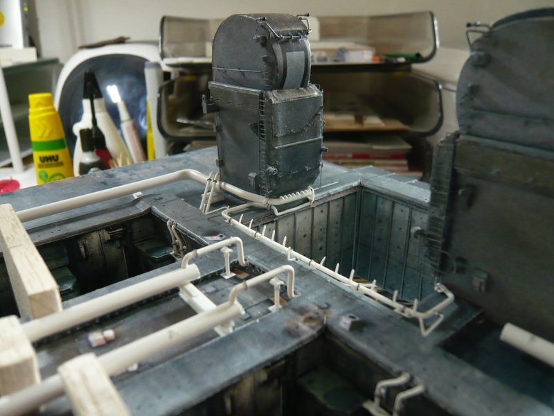 as one can see here, 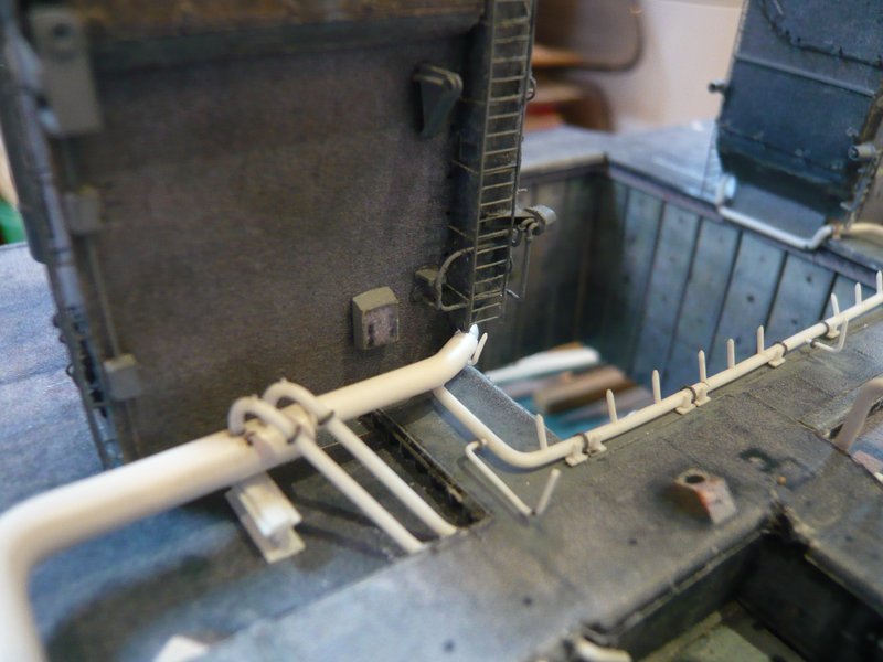 across the Firex line and below the ladder through, and left past on the angled nozzle.  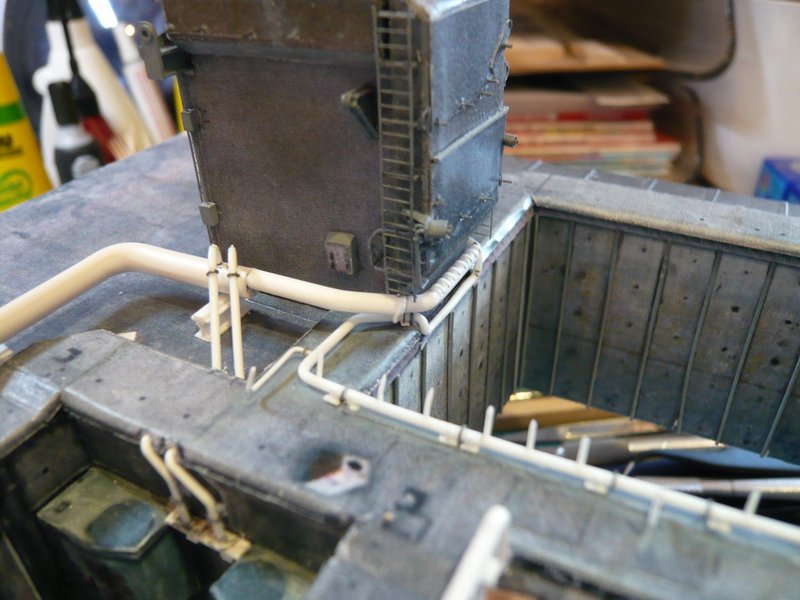 Good that it was not tighter, but fortunately it has worked well.  
__________________
Greetings from Germany Manfred Under construction: Launch Pad 39A with Challenger STS-6 (1:144)
|
|
#1163
09-12-2016, 06:25 AM
|
||||
|
||||
|
Hi everyone ,
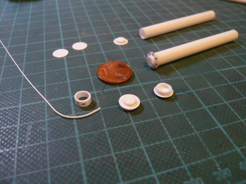
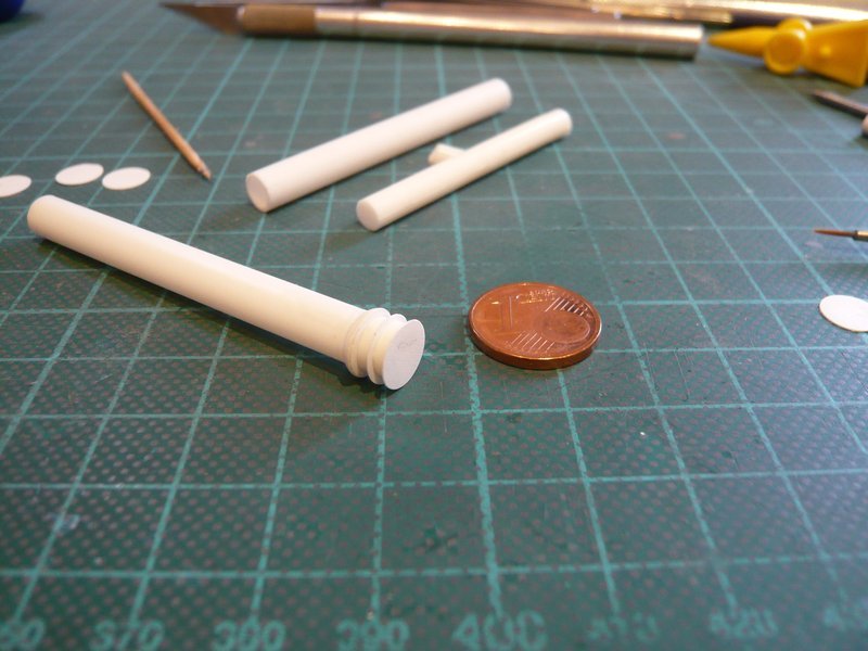
after a little forced break it should now go further.  At first there is still the supplement to the nozzle pipe on LH2 TSM, which now also waiting for the final assembly and mounting to the 24'' ring line, which will follow soon.  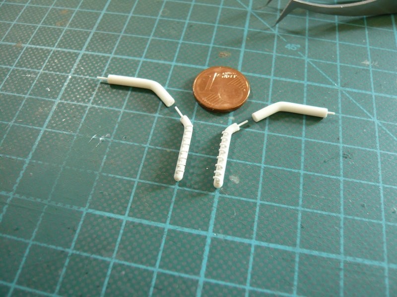  And so I would then also have crossed through the maze of SSWS pipes.  After lately the pipe diameters became smaller from 24''-18''-16''-12''- 9'' down to 6 '', it now once again goes back to the thickest 36'' pipes (Ø 6,3 mm), through which both ring lines being supplied with water. The connecting pieces of the feed pipes in the corners of the SRB chambers I had mounted already during bending of the ring lines. 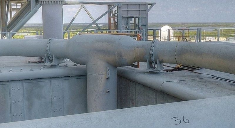 Source: NASA And now it comes to the lower end of the tube with the connecting piece, for whose items I have again estimated their dimensions. 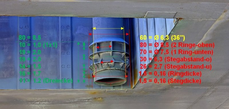 Source: Troy McClellan For the construction of this connecting piece I have imagined that I could cut the 6.3 mm tube into short rings, which are subdivide by punched plastic discs (0.15 mm) and finally are glued together.  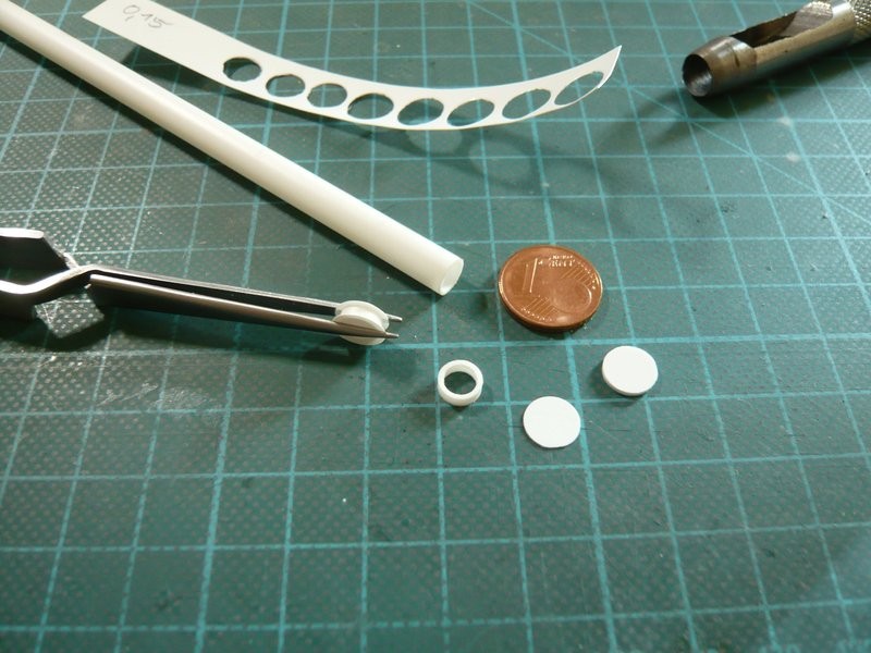 The more difficult part of the exercise subsequently follows, when these tiny stiffening ribs and corners must be glued all-around, for which I already have an idea,  but what could become quite a tricky fumbling. but what could become quite a tricky fumbling.  As far as for today.
__________________
Greetings from Germany Manfred Under construction: Launch Pad 39A with Challenger STS-6 (1:144)
|
|
#1164
09-20-2016, 05:02 PM
|
||||
|
||||
|
Hello together,
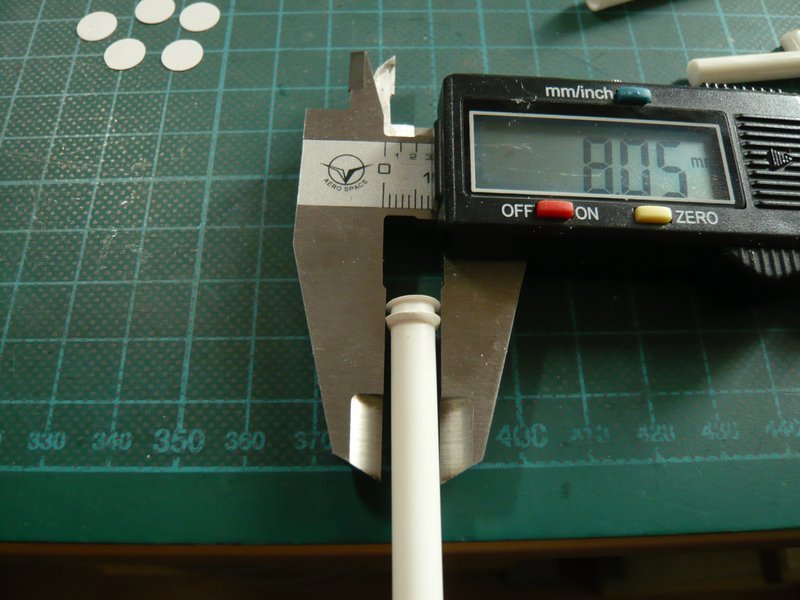
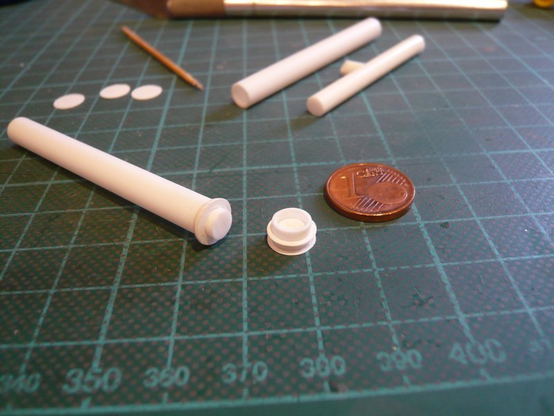
before the tiny stiffening ribs and corners get their turn, the subdivided construction of the connecting piece must first be put into practice what I first have tried, whereby I proceeded from top to bottom. This starts up on top with this conical ring (truncated cone), about which I've been thinking. One possibility would be to file off a circumferential 45° bevel to a 1 mm thick slice (Ø 8,0 mm), what is tedious and not easy if it should become perfectly round, as one can see.  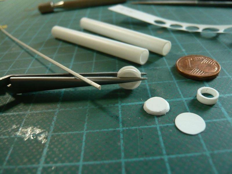 Then one could also imagine a ring of triangular profile (60 °), as can be seen on the tweezers. That is not of Evergreen, but in an architecture shop I have found and was very happy.  But already at the hot bending of the Rings proved the profile to be quite stubbornly because it has aligned to the wood core, as it wanted,   and has also still twisted itself. 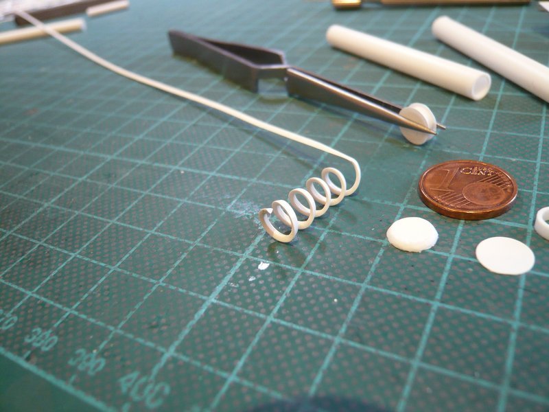 Thus, it could not so nice and smoothly be attached to the 36'' feed pipe (Ø 6,3 mm) as I would have liked. As can be seen, namely a gap emerged at the top, what I do not like and still has to be filled somehow.  But then one could also mould the bevel with Apoxie Sculpt. But then one could also mould the bevel with Apoxie Sculpt.  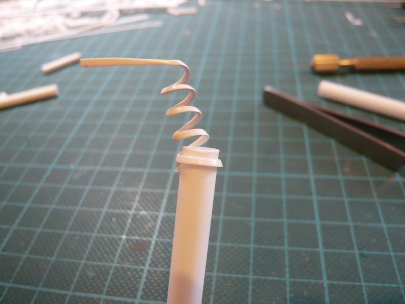 So I wanted to try something else and have glued a slightly pre-bent triangular strips all around with CA. 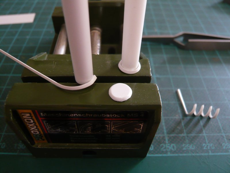 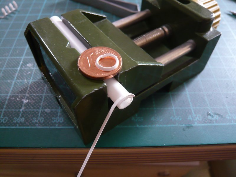 Although this has worked a little better than before, but a smaller gap could not be avoided altogether. 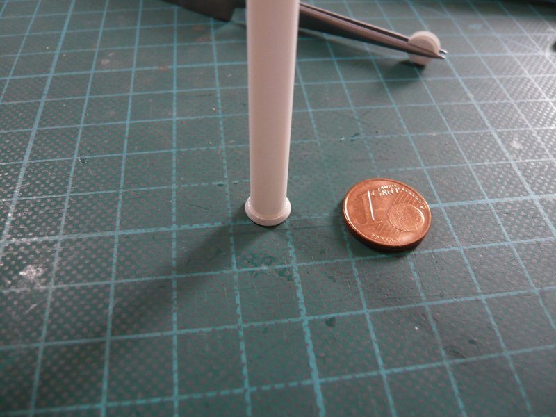 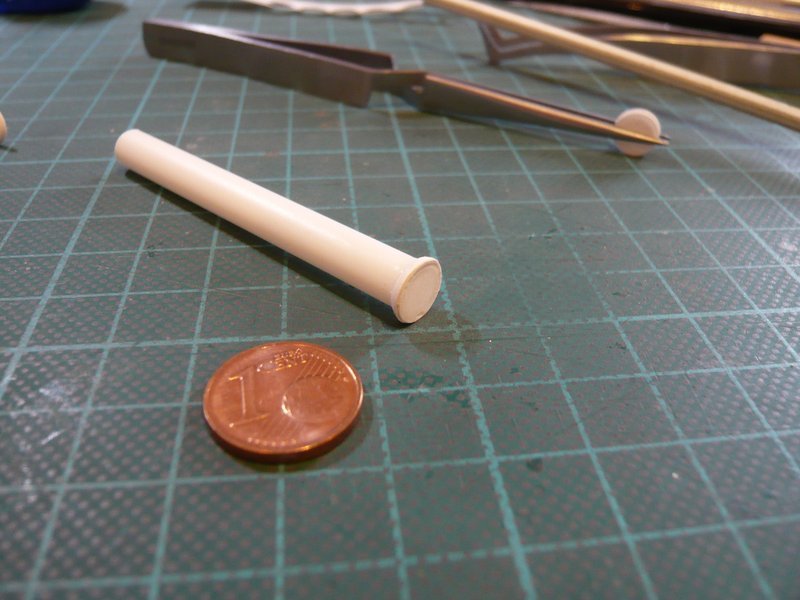 But with the result I first times contented myself in order to test the further construction. But I definitively did not wanted to glue together the rings and discs in order to make even possibly corrections of segment heights. That's why I have cut small 1 mm base plates of a sprue, which correspond to the inner diameter of the rings.  These plates should serve as a base, on which then the rings are placed loosely without glue. 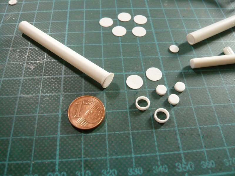 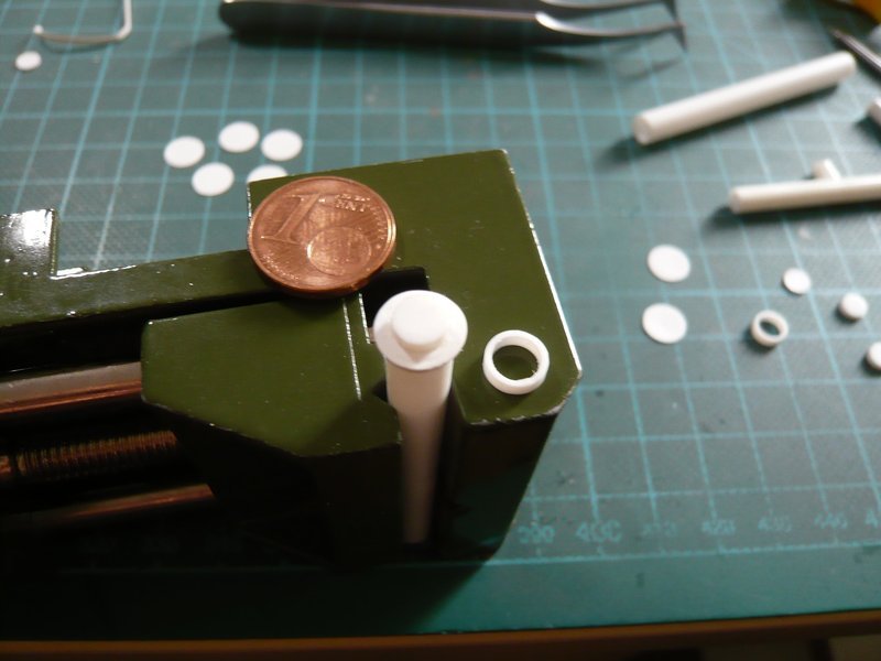
__________________
Greetings from Germany Manfred Under construction: Launch Pad 39A with Challenger STS-6 (1:144)
|
|
#1165
09-20-2016, 05:03 PM
|
||||
|
||||
|
Then followed the stepwise construction of the connecting piece with the parts, whereby one has to pay attention on a central alignment of the slices and rings.
  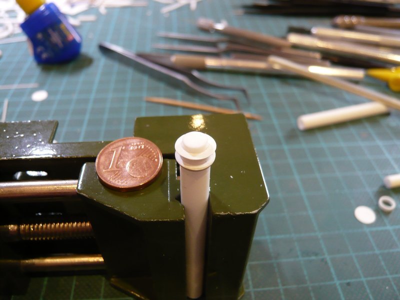 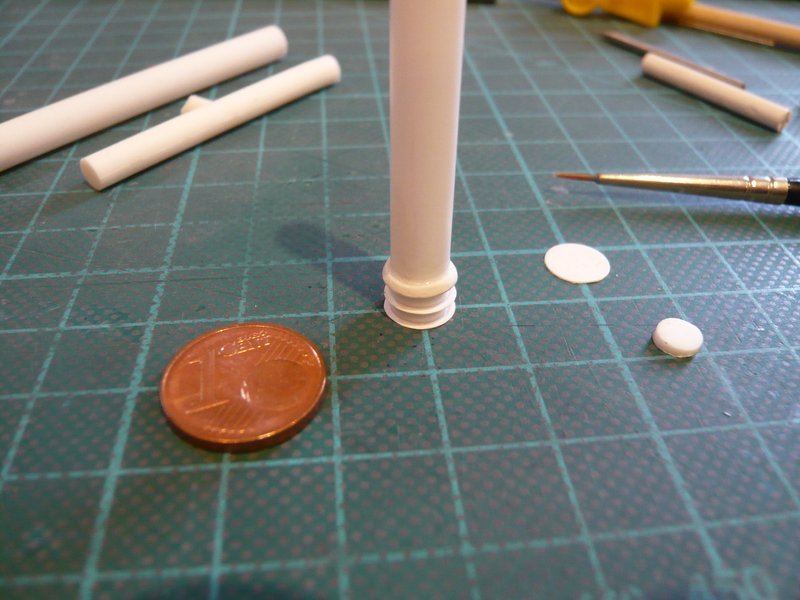   On the lower tubular segment of the connecting piece sits a double-profile ring, as can be seen in this picture. 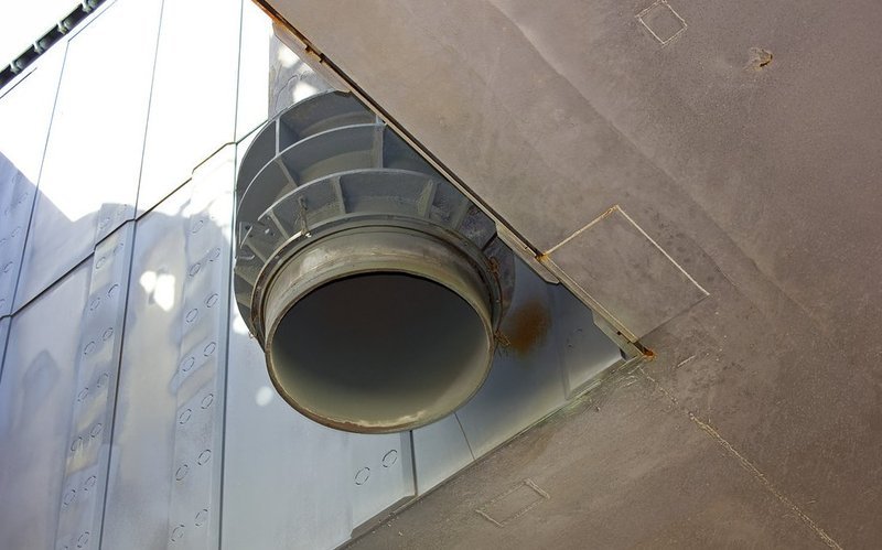 Source: Troy McClellan In order to scratch this ring simplified, I glued an Evergreen strip (0.4 mm x 0.5 mm) around the lower tubular segment. 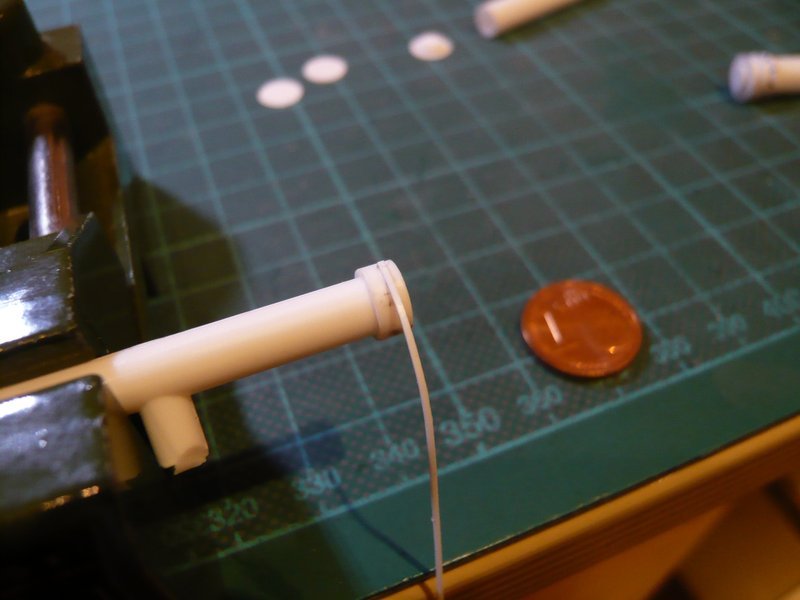 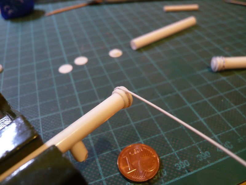 Then I have put together all the segments, whereby the connecting piece slowly takes its shape. 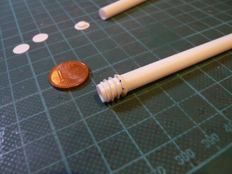 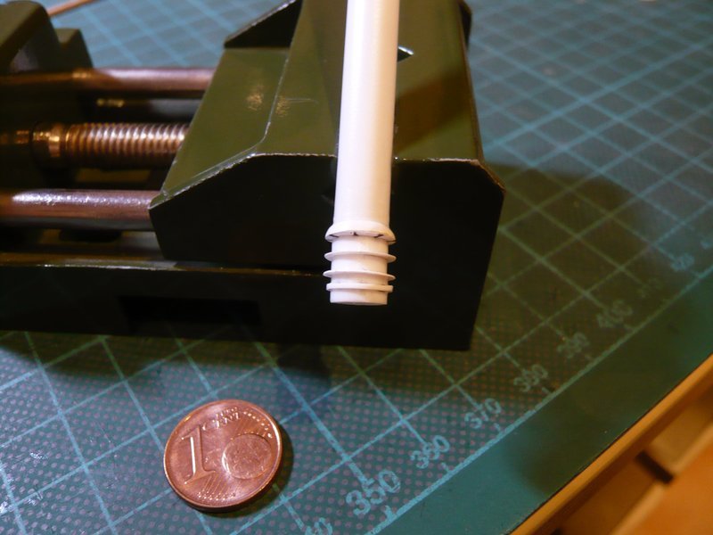 However the lower ring appears a little too massive, maybe a strip 0.25 mm x 0.5 mm would look something more pleasing from what I could still try,  especially because the connecting piece still can be disassembled. especially because the connecting piece still can be disassembled.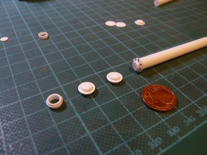 Now then are still missing the stiffening ribs and corners, which I will make next time.
__________________
Greetings from Germany Manfred Under construction: Launch Pad 39A with Challenger STS-6 (1:144)
|
|
#1166
09-20-2016, 05:37 PM
|
|||
|
|||
|
Nice to see you posting again Manfred! Still following along. It's a pleasure.
__________________
This is a great hobby for the retiree - interesting, time-consuming, rewarding - and about as inexpensive a hobby as you can find. Shamelessly stolen from a post by rockpaperscissor
|
|
#1167
09-21-2016, 02:37 PM
|
||||
|
||||
|
Thanks eliott for your nice words.
 I'm also glad if you can enjoy my small steps.
__________________
Greetings from Germany Manfred Under construction: Launch Pad 39A with Challenger STS-6 (1:144)
|
|
#1168
09-23-2016, 08:27 AM
|
||||
|
||||
|
Hello everybody,
as already indicated, the lower ring of the connecting piece I have still slimmed down a bit and by using a thinner strip of 0.25 mm x 0.5 mm. 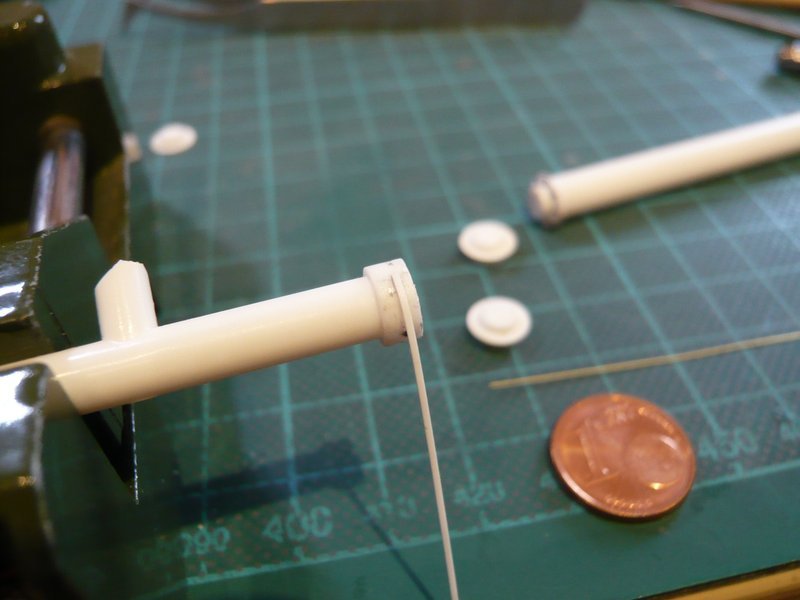 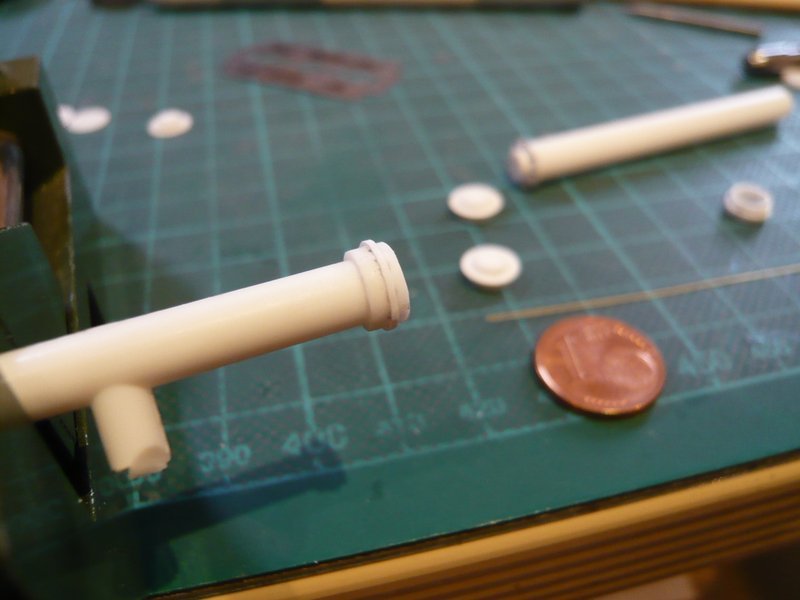 And in a direct comparison of both rings the optic of the new ring (right) looks something more pleasing, I think so,  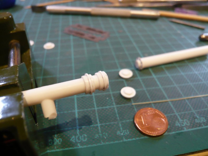 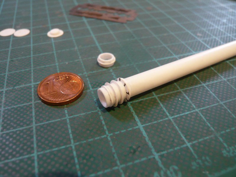 but that is as always a matter of taste. 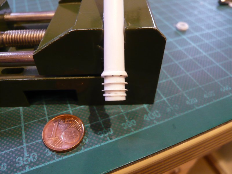 And now followed the upper eight stiffening ribs, for what I have cut short Styrene strips (0.15 mm), which are a little longer in order to assemble and glue easier,  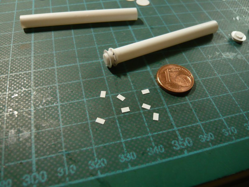 which I have again done with MEK. 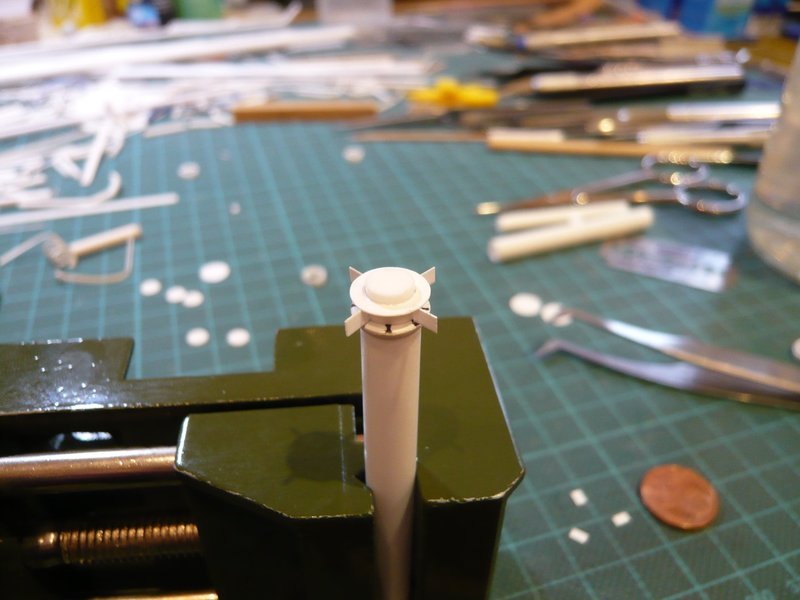 But do not worry, I'm not on the wrong path, this should not become a turbine rotor.  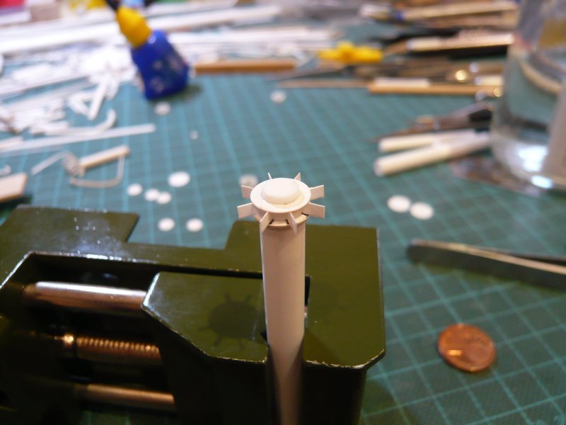 And now only the protruding ends had to be carefully cut off with a razor blade from top to bottom, 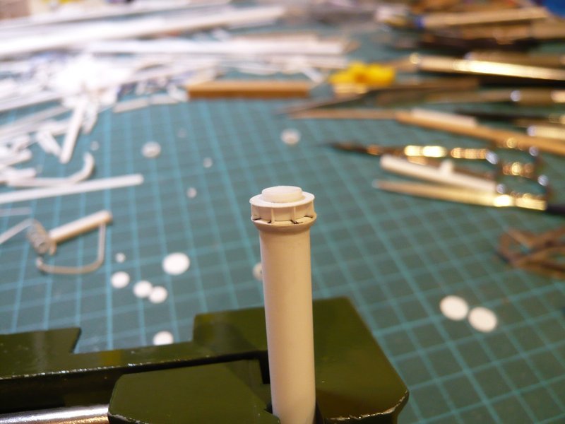 which has pretty well worked. However I fear, that the tiny stiffening triangles certainly shall become much more complicated and stressful. 
__________________
Greetings from Germany Manfred Under construction: Launch Pad 39A with Challenger STS-6 (1:144) Last edited by spacerunner; 09-24-2016 at 04:51 PM.
|
|
#1169
09-24-2016, 04:56 PM
|
||||
|
||||
|
Hello folks,
to be frightened is not an option, and so I have got down to work, whereby the manufacture of the triangular stiffening ribs happened according to the same recipe for success. First, I have cut 0.8 mm wide strips of 0.15 mm Styrene and separated from these then 3 mm long sections. 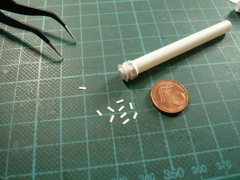 But now came the gluing, and I first tried with the normal Revell glue. But due to the minimal contact zones (0.8 mm x 1 mm) it is quite problematic to establish a sufficiently strong connection. For the fixation of the strips it was initially sufficient, but if they would survive the reducing of the supernatants, I was not sure. 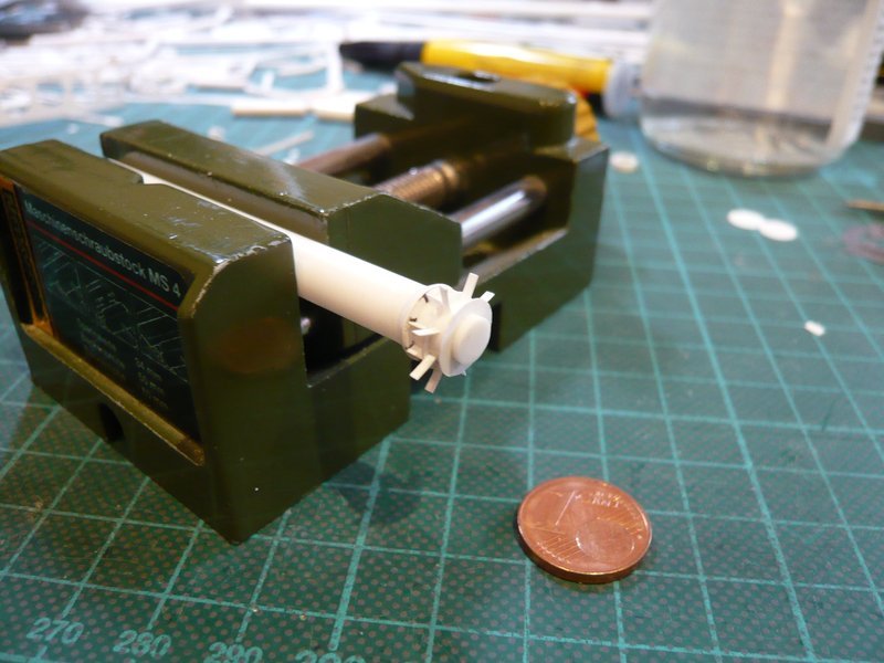 Therefore I wanted to stabilize the contacts even from both sides with MEK. But that failed because the MEK dissolves the contact point too strong, whereby the strip has lost his footing and tipped over. At the 2nd attempt I have therefore the strips initially fixed only with CA, but this is quite difficult because the correct location must be found immediately and the seat almost can not be corrected. But with a little practice and a quiet hand then I have succeeded. 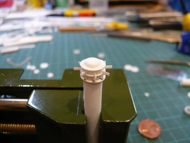 And after that, the strips then could be stabilized with MEK yet again. 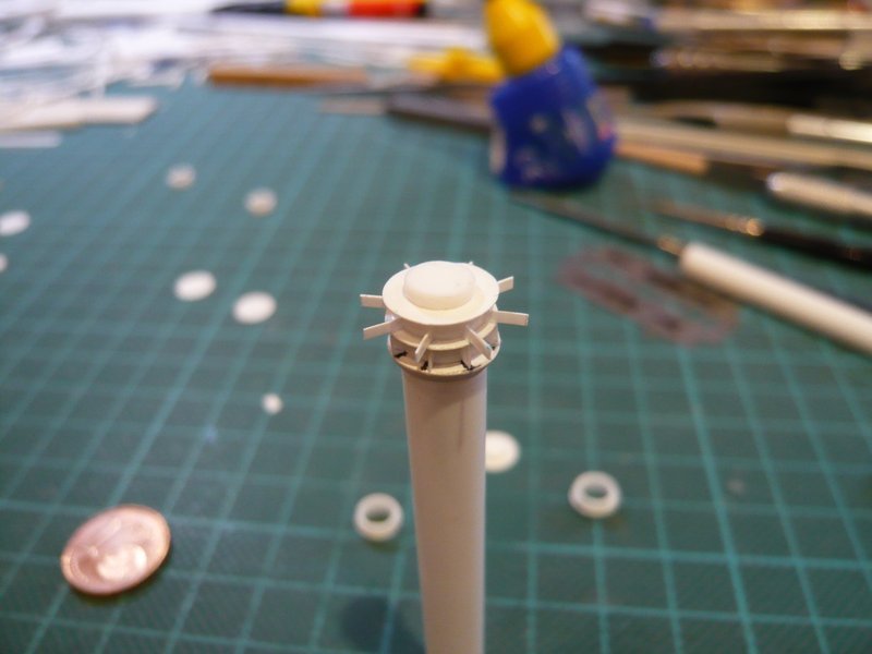 In this position I then first have cut off the supernatants perpendicular with the razor blade. 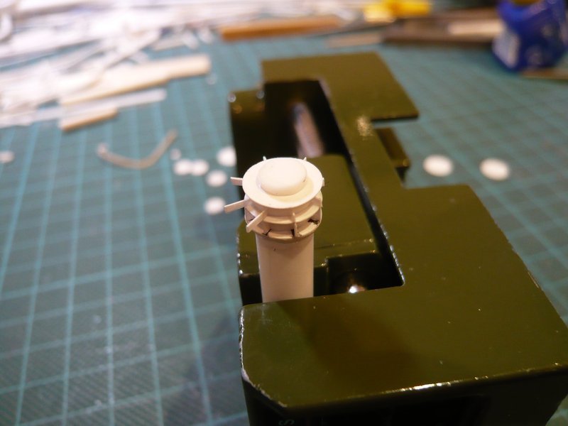 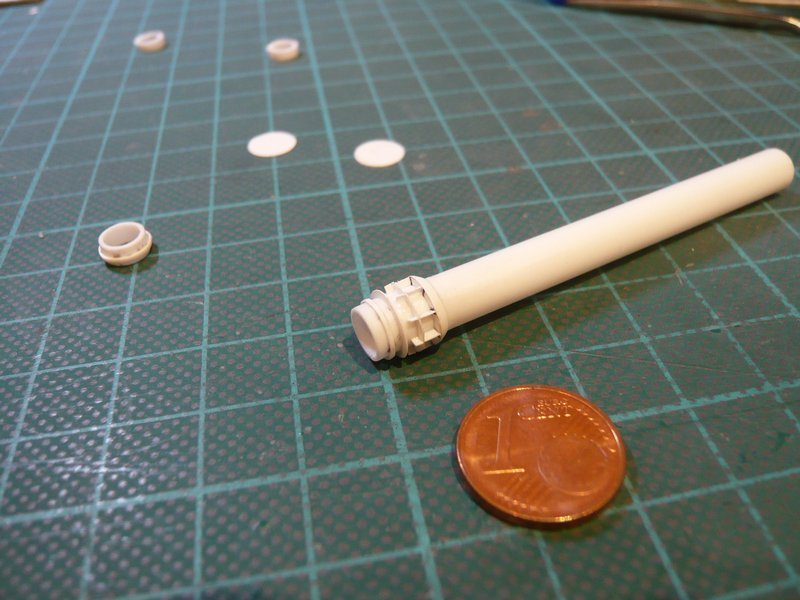 And then I have gently cut off the 45° bevels, which to my surprise was actually relatively easily doable.  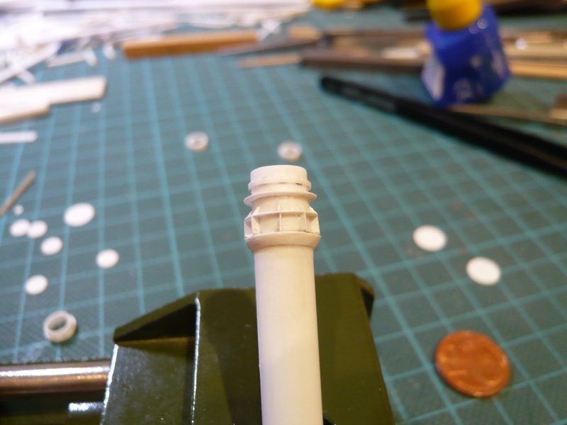 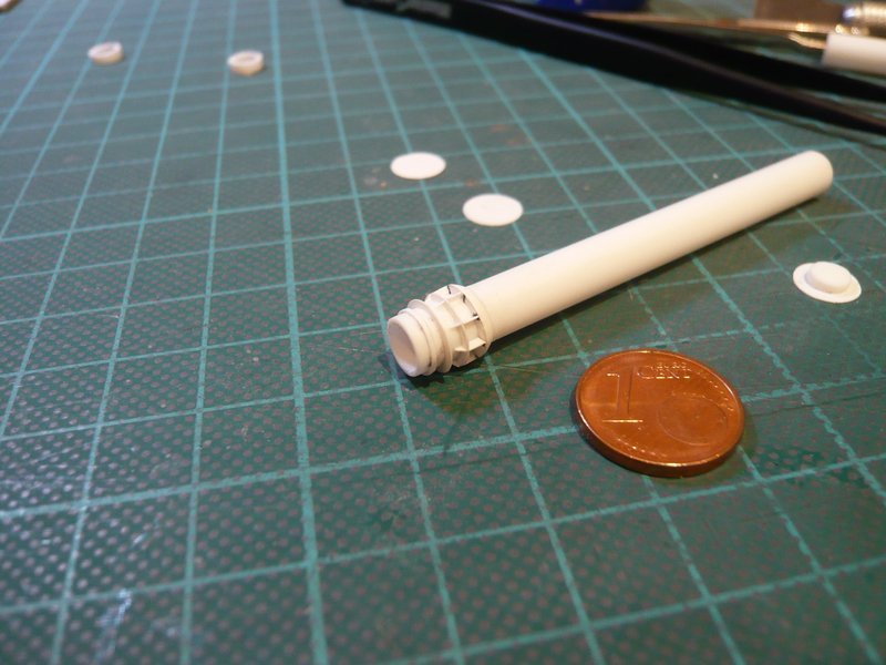 And now I'm actually quite confident that I will be able to scratch the remaining triangular ribs on both sides of the lower disc also. Upon closer examination one can see, that there are about twice as many ribs as on the middle disc, which are also unevenly distributed over the circumference. 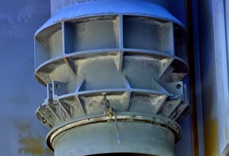 Source: Troy McClellan And then there are as a further delicacy still three pairs of rectangular ribs (0.8 mm x 1 mm) with holes (Ø 0.2 mm), which are staggered to 120°,  whereupon I cannot probably renounce, or maybe yet? whereupon I cannot probably renounce, or maybe yet?  Let's see what we can do!
__________________
Greetings from Germany Manfred Under construction: Launch Pad 39A with Challenger STS-6 (1:144)
|
|
#1170
09-24-2016, 06:16 PM
|
||||
|
||||
|
Wow, some very interesting new pieces! This keeps getting better and better

__________________
PAPERENGINEER Designs in progress: -C-2A Greyhound -Br.1050 Alize
|
 |
|
|


 Linear Mode

