


|
|
|
#991
 03-23-2016, 09:10 AM
|
||||
|
||||
|
Yeah, yeah, yeah!
 But more than half the time I'm spending for for searching and studying of suitable HiRes reference photos for scratching the details and casually for getting to know NASA's fascinating Space Flight Technology.  Therefore, I have never set a deadline for this challenging long-term project and do not race against time. And over time, in addition to the own experience and finger dexterity also the own claims are growing and thus the project scope ...  My goal is a complete diorama of the Launch Pad 39A at the time of the Challenger's first mission STS-6, and not to forget - with lighting ...  BTW, the Airfix Shuttle Stack is a good choice, a lot of success and even more fun.  
__________________
Greetings from Germany Manfred Under construction: Launch Pad 39A with Challenger STS-6 (1:144) Last edited by spacerunner; 09-25-2016 at 02:41 PM. 
|
|
#993
03-24-2016, 12:10 AM
|
||||
|
||||
|
Then come on buddy and let's see your start.
__________________
Greetings from Germany Manfred Under construction: Launch Pad 39A with Challenger STS-6 (1:144)
|
|
#994
03-24-2016, 12:55 AM
|
||||
|
||||
|
Hello everybody,
the nightmare with the "cartridge belts" unfortunately is not over yet, but now the belts for the two central Rainbirds A-1 and A-2 are prepared and so this tricky and stressful chapter finally completed.  This are the screws rings on the upper tubes with Ø 6,3 mm, all fine fixed by magnets and with the support strips (0.25 x 0.75 mm) placed for the MEK gluing. 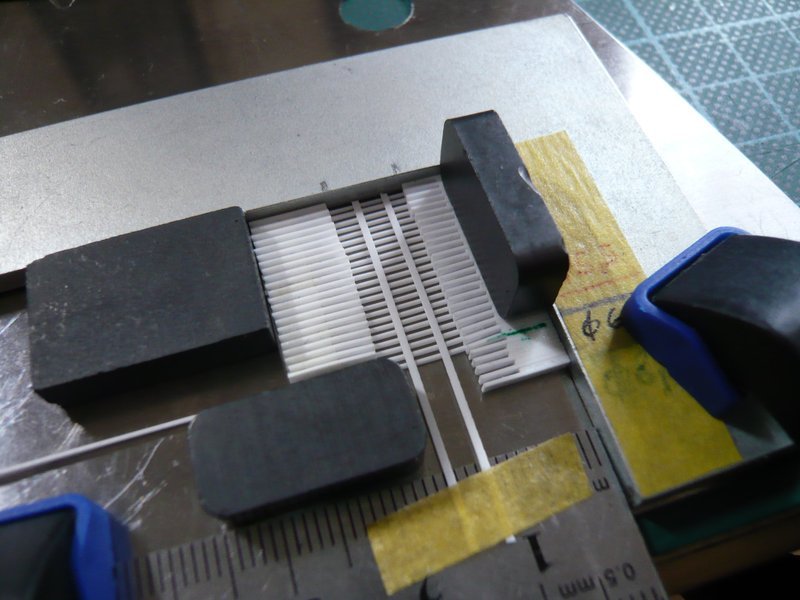 Here the strips are already glued and the grid can be further processed. 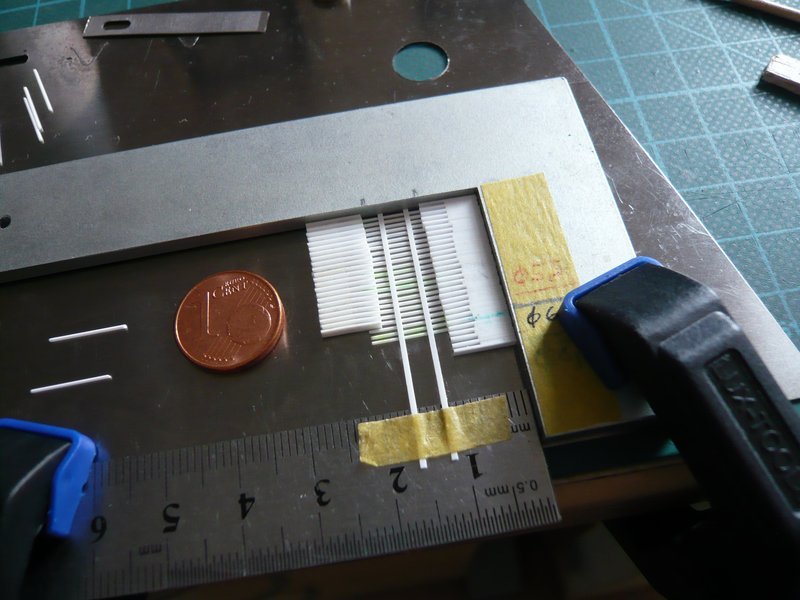 After removing of the templates the overlap can be reduced on both sides to 0.75 mm. 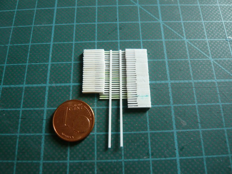 Left are the top two belts for the Birds A-1 and A-2, and on the right for comparison for the leaner Birds B-3 and B-4. 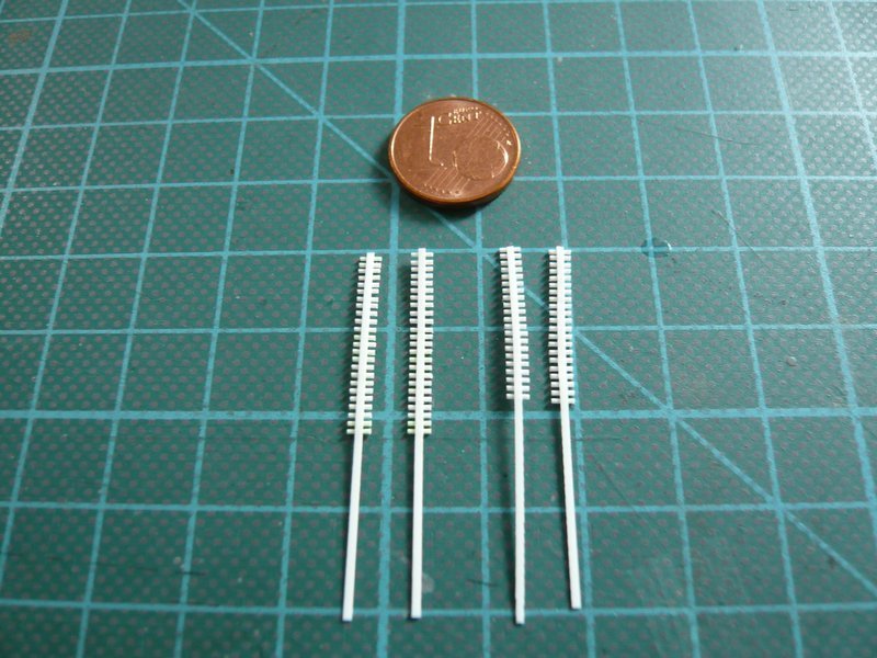 And this become the two lower belts on the thicker tubes with Ø 8,0 mm for the Birds A-1 and A-2. 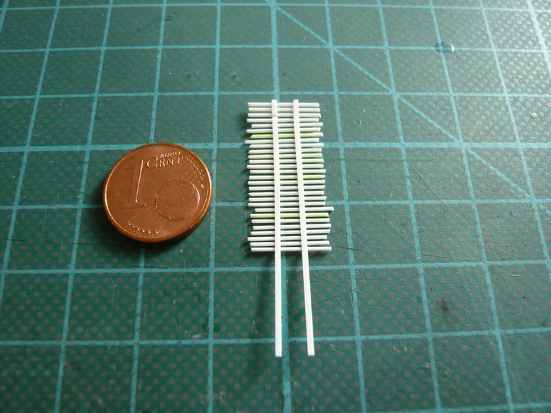 Here they are now cropped step by step, 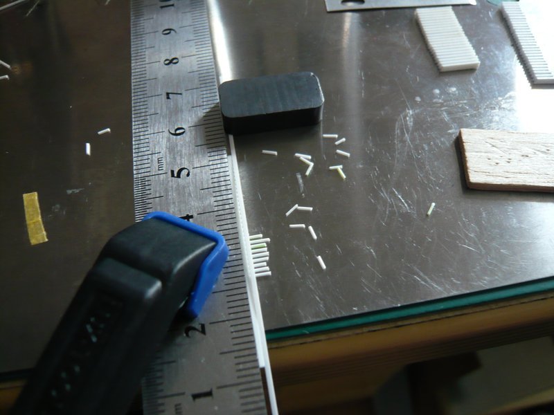 for the lower ring with overlap (0.75 mm) on one side, 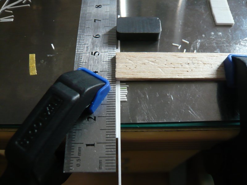 and for the top ring on both sides. 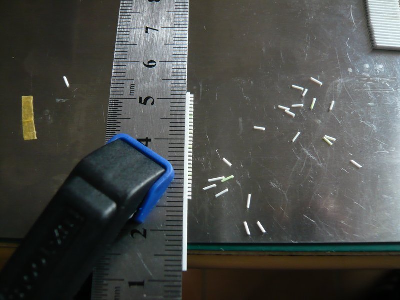 These are the two bottom screws belts for the Birds A-2 (left) and A-1 (right)  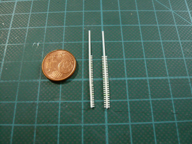 and here the two pairs for the Bird A-1 (left) and A-2 (right). 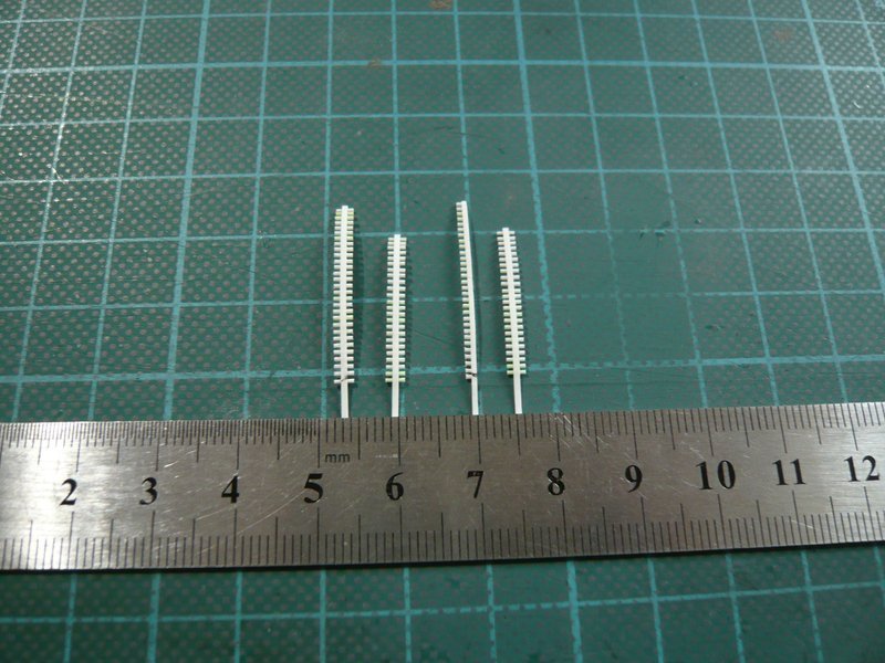 And so it is finally done.  These are from left to right all the "cartridge belts" pairs for the remaining five Birds B-2, B-3 and B-4, as well as A-1 and A-2. And when they are now lying there, the laborious sweaty detail work can be imagined hardly. 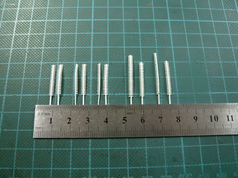 Therefore I am glad that this ordeal is now over  and the mounting can follow. and the mounting can follow.
__________________
Greetings from Germany Manfred Under construction: Launch Pad 39A with Challenger STS-6 (1:144)
|
|
#995
04-06-2016, 10:43 AM
|
||||
|
||||
|
Hello everybody,
after the recreative Easter break, it will now go on with the Rainbirds. Because I did not immediately want to continue with the "Cartridge belts" and have needed some change, I have intensively considered the central Rain Bird A-1 with the four cute flange tubes and thought how I could possibly scratch it.  On most pictures one can see only revision openings on the flange tubes, which are closed with 12 screws,  Source: NASA but in a photo stream of Andrew Scheer I have found a picture in the opened state.  Source: flickr.com (Andrew Scheer) A somewhat bold idea I have had already.  But in order to test this, one needs the dimensions of the parts, which are the flange tube with the covers and bolts and a corresponding 1:1 sketch. But in order to test this, one needs the dimensions of the parts, which are the flange tube with the covers and bolts and a corresponding 1:1 sketch.The size of the flange and cover can be relatively easily determined from frontal shots like this, by using the diameter of the lower tube with Ø 7.9 mm as reference, which would be approx. 3.5 mm. For that I can use my Punch & Die Set again. This results in a diameter of the bolt circle of Ø 2.9 mm and for screws Ø 0.4mm, which already shows how tiny these parts would be again. 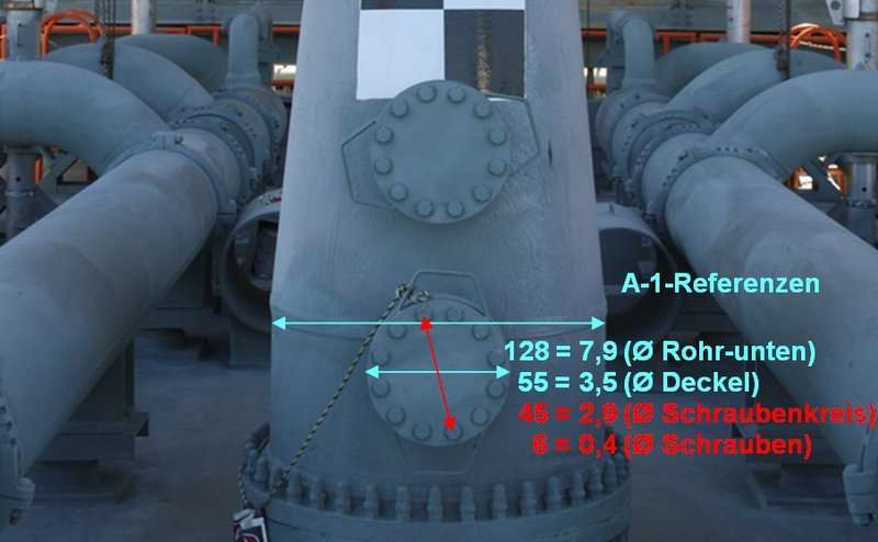 Source: NASA Somewhat more difficult it is with appropriate images, where one can see the lateral structure of these flange tubes undistorted for determination of the dimensions. Since most photos, such as the first image above, show the Rainbird more or less from oblique perspectives, these photos can not be used unfortunately. But in a NASA streetview panorama I have found a usable lateral view and so I was able to determine the length of the flange tube as well as the thickness of the flange and cover, and the gap between them, inclusive the screw length. 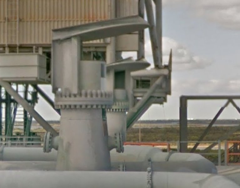 Source: NASA So I have drawn this sketch (1:1), where the bird A-1 already looks a lot smaller than on the pictures. 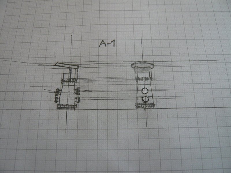 And now to the flange with cover and 12 screws and my conception for scratch-building these parts. First, I have drawn the layout of the bolts on the flange cover something enlarged, and then this graphic was reduced to 3.5 mm Ø, in which for further procedure actually only the bolt circle is important. From this bolt circle I wanted to create me a transparent mask for transmitting the positions of the 12 screws onto the cover (Ø 3.5 mm x 0.2 mm) as well the flange (Ø 3.5 mm x 0.5 mm), in order to drill them out, but the procedure somehow appears to be adventurous, right?  And into the holes of the discs I then wanted to glue the bolts (Ø 0.4 mm) with a little supernatants, insofar as to my idea or theory. And into the holes of the discs I then wanted to glue the bolts (Ø 0.4 mm) with a little supernatants, insofar as to my idea or theory. 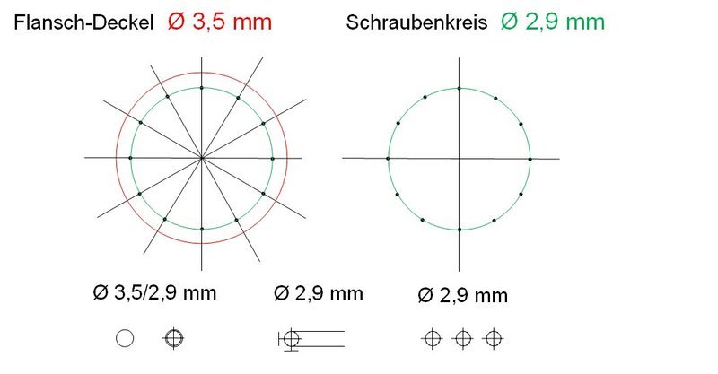 And as I said, so done. The paper template of the bolt circle (Ø 2,9 mm), I have carefully pierced with a needle on a transparent film and then drilled with a drill (Ø 0.35 mm), which was not easy and less funny and sometimes went wrong. 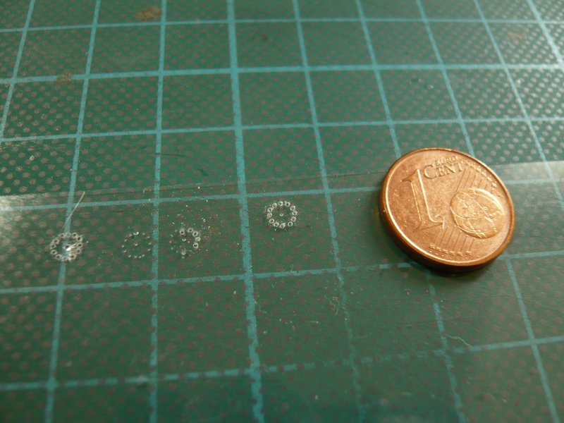 Far more difficult was drilling of the cover with applied template that can easily slip, 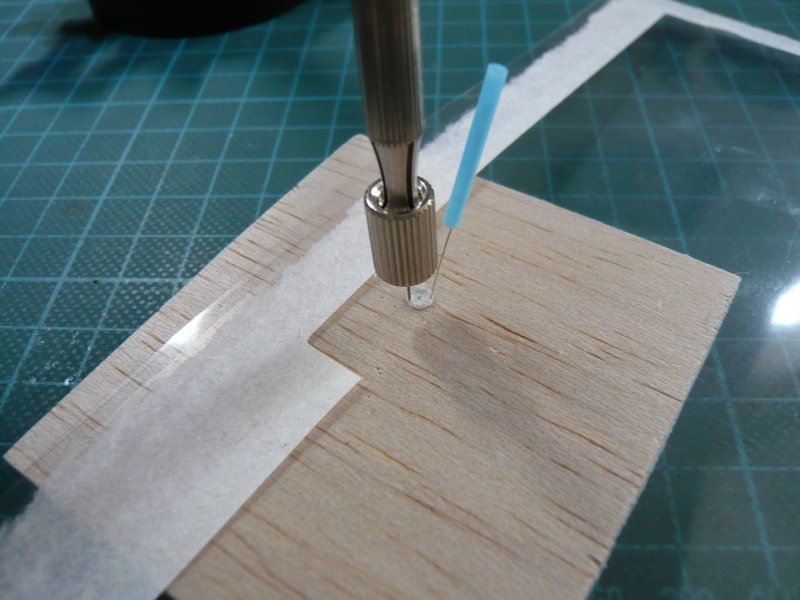 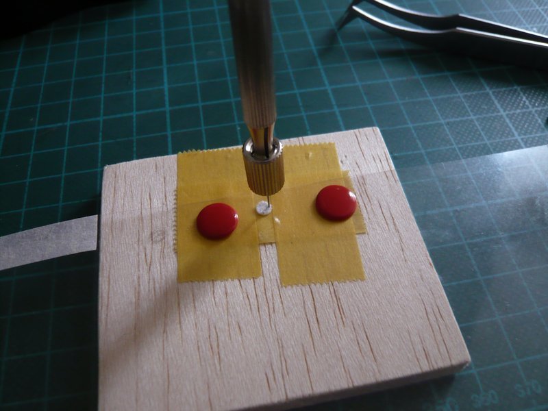 which may lead quickly to excentric bolt circles or waste.  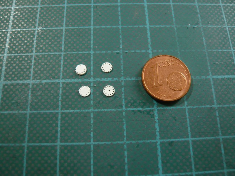 But this cover here is quite well succeeded already. 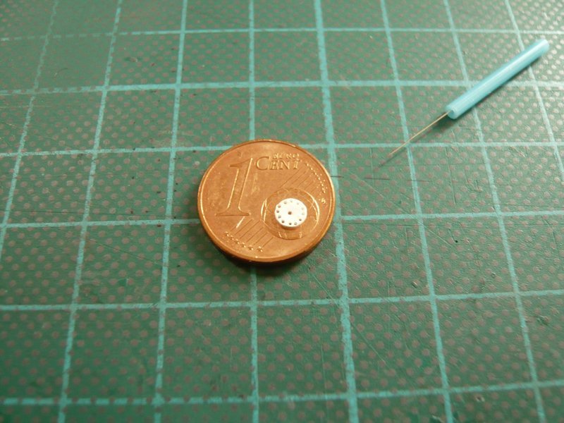 And here I have threaded two small rods Ø 0,3 mm, which unfortunately are somewhat too thin. But there are no rods with Ø 0.4 mm, and for Ø 0,5 mm will probably not be enough space on the 2.9 mm bolt circle. 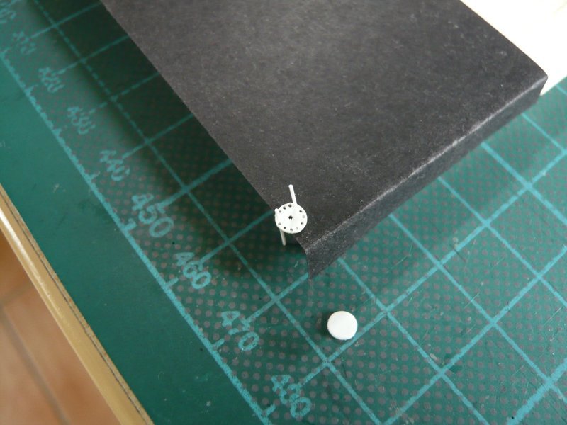 Maybe there are other options too, but for today it should be enough.
__________________
Greetings from Germany Manfred Under construction: Launch Pad 39A with Challenger STS-6 (1:144)
|
|
#996
04-06-2016, 05:33 PM
|
|||
|
|||
|
Great work Manfred; conceiving an idea and bringing it to (tiny) fruition. Looks like a master at work.
__________________
This is a great hobby for the retiree - interesting, time-consuming, rewarding - and about as inexpensive a hobby as you can find. Shamelessly stolen from a post by rockpaperscissor 
|
|
#997
04-07-2016, 03:49 AM
|
||||
|
||||
|
Thanks elliott,
 this technique is very tricky, maybe I'm going willy-nilly have to consider another method.
__________________
Greetings from Germany Manfred Under construction: Launch Pad 39A with Challenger STS-6 (1:144)
|
|
#998
04-07-2016, 04:14 AM
|
||||
|
||||
|
I have also a new idea ...
__________________
Greetings from Germany Manfred Under construction: Launch Pad 39A with Challenger STS-6 (1:144)
|
|
#999
04-07-2016, 10:15 AM
|
||||
|
||||
|
Hi all,
so I still have fiddled a bit more. To illustrate the dimensions of the individual parts of the flange tube here is my assessment as far as one can still realise it. As the reference measure I've used the diameter of the upper tube Ø 6,3 mm. 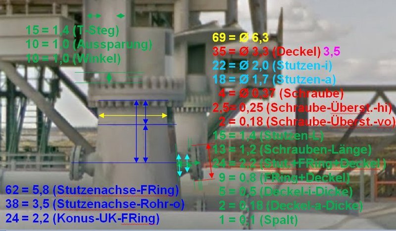 Source: NASA Here I have further tried this tricky variant, have transferred the bolt circle (Ø 2,9 mm) in the same manner onto the flange (Ø 3.5 mm x 0.5 mm) and subsequently drilled out, but that was pretty difficult to do without slipping away.  And then I threaded rods with Ø 0.3 mm as screws dummies into the holes of both discs, but as I said, which are unfortunately a bit too thin. And then I threaded rods with Ø 0.3 mm as screws dummies into the holes of both discs, but as I said, which are unfortunately a bit too thin. 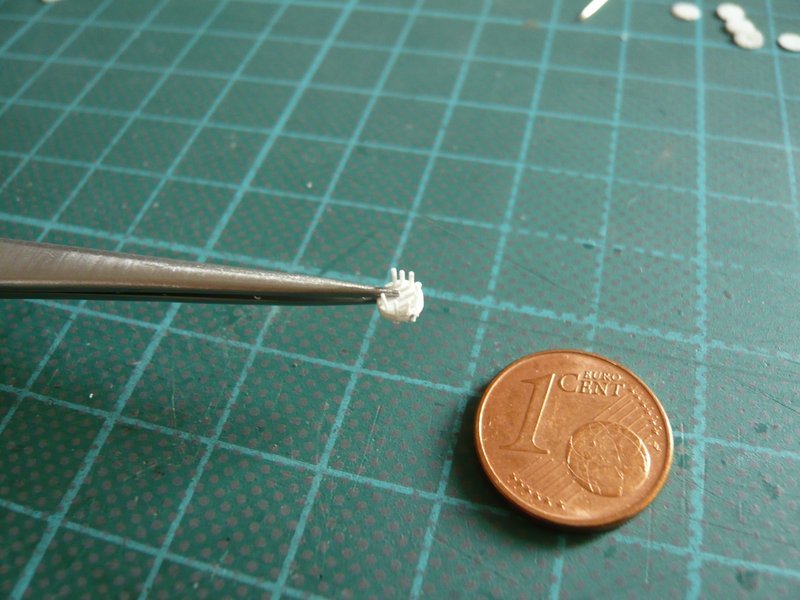 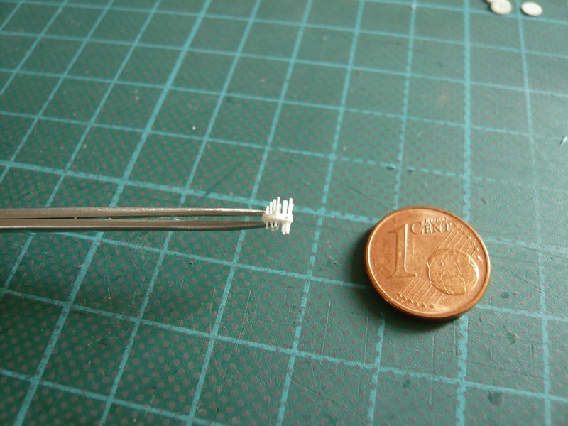 Anyway, this procedure is feasible, but is all in all a very elaborate method. That's why I tried yet another variant with stamped discs, for which I have used the smallest punch (Ø 0,6 mm) of my Punch Set. Here one can see the flange (0.5 mm) with the cover (0.2 mm), both Ø 3.5 mm, in between I have placed a slightly smaller disk (0.1 mm) for the gap. Thus, the flange with cover incl. gap has a total thickness of 0.8 mm, which fits well. 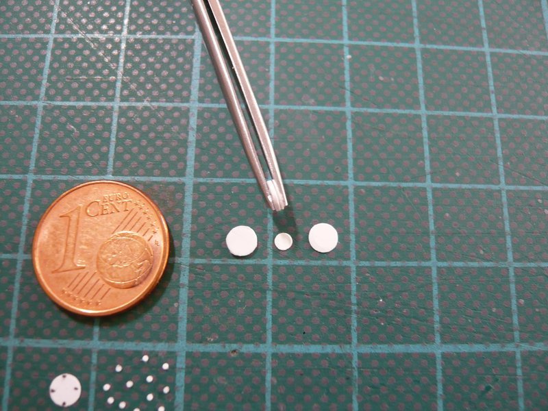 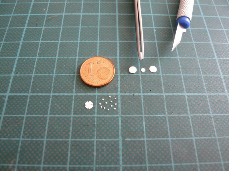 Then I started to glue these small discs with MEK, 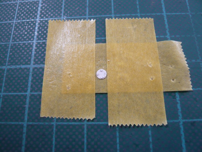 Then I started to glue these small discs MEK, but quickly noticed that the distances on the bolt circle are not sufficient, what was to be feared. With smaller discs of Ø 0.3 to 0.4 mm but this variant would be feasible too, but I would have to cut tiny discs from corresponding rods.  Czech Master's Kits (CMK ) offers some great kits with small rivets and even hexagonal screw heads with drill template and drill, but unfortunately only down to minimal Ø 0.8 mm. 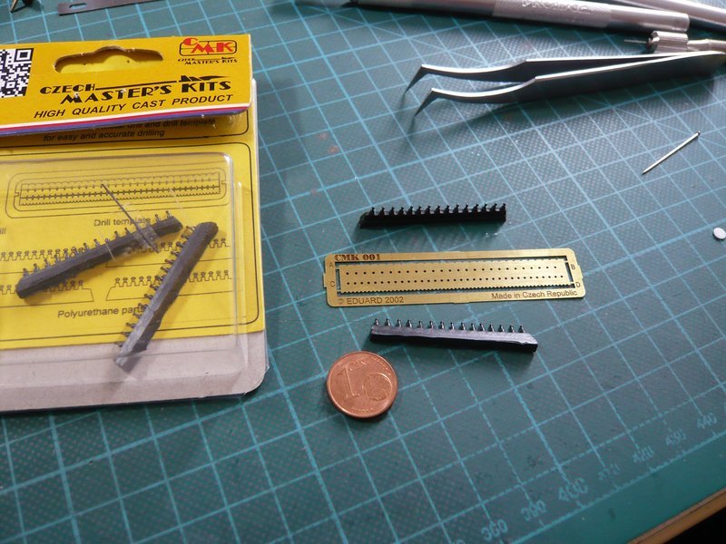 But through my Punch & Die Set I had yet another idea. Why I should not try to reverse the principle and not to glue the screw heads, but to press them with a thin stamp into the Styrene sheet but without to pierce it, so similar to the rivet wheels of aircraft modelers?And so I have tested it on a sheet (0.2 mm), for which I have clamped a drill with Ø 0.4 mm reversed and then gently pressed with its backside into the Styrene. And the result has pleasantly surprised me, as one can see here, because it looks pretty well and usable.  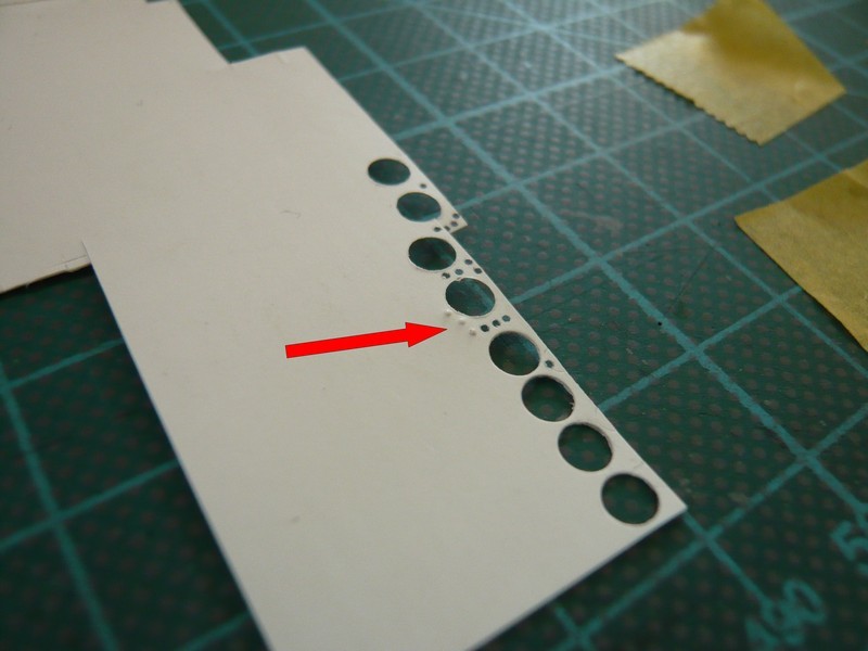 And this technique, I then tried on a cover (Ø 3.5 mm), without exactly mark the positions, only drawn by eye. This here is the underside with the imprints, 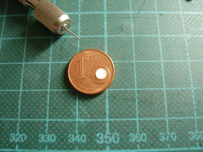 and here the top side with the screw heads.  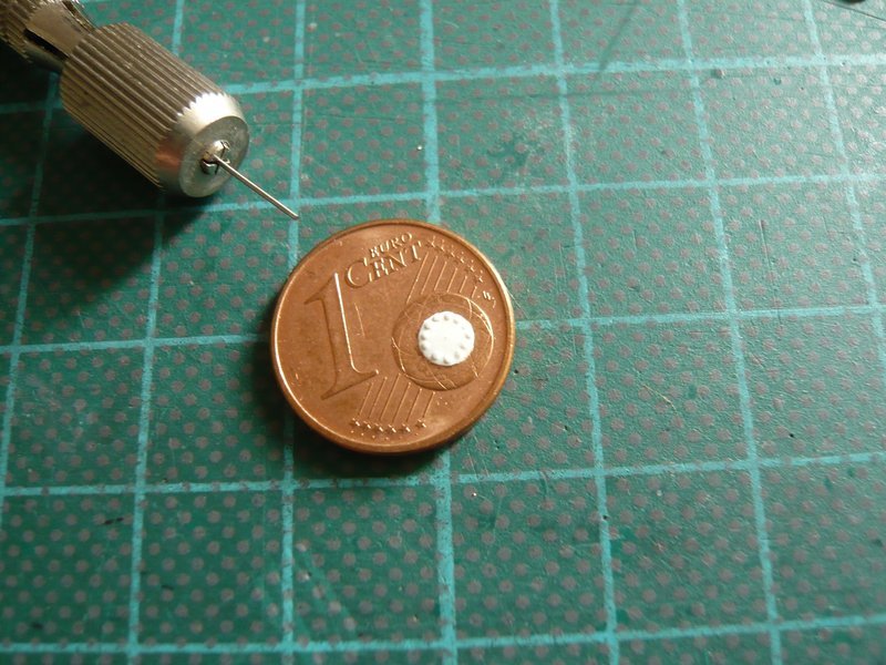 And this result might please already, right? But since the flange-disc (0.5 mm) unfortunately is too thick for this technique, I must still find any other solution therefor.
__________________
Greetings from Germany Manfred Under construction: Launch Pad 39A with Challenger STS-6 (1:144)
|
|
#1000
04-07-2016, 11:38 PM
|
||||
|
||||
|
Hello friends,
and this variant I've tried, and the result, I will show you shortly. Here's another stamped cover,  and here already the finished composite flange with cover.  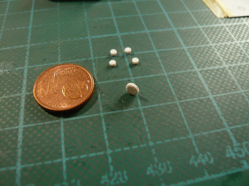 Now only missing the flange tubes (Ø 1.8 mm), which I have stamped from 1 mm styrene.  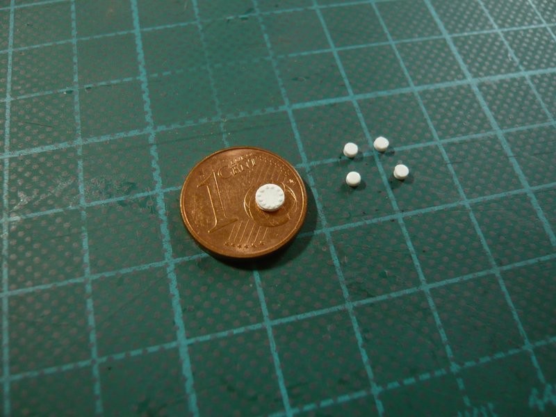 And so the first of four flanges with cover and 24 screws is completed.  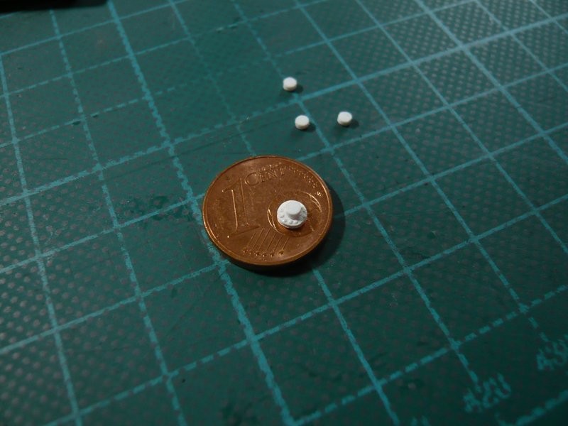 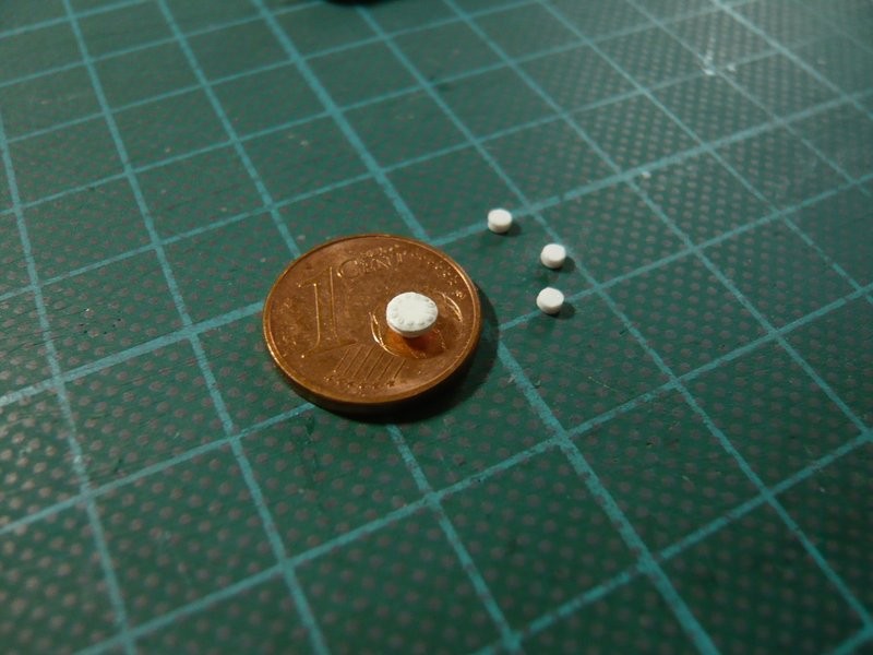 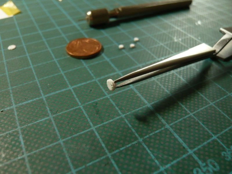 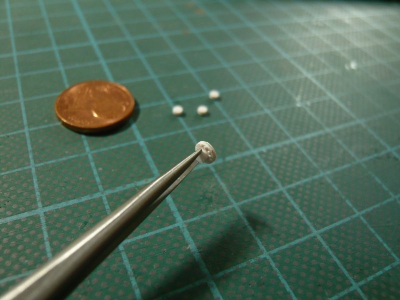 And here is a first test on the knitting needle, that will be used for the lower tube and the conical midsection. 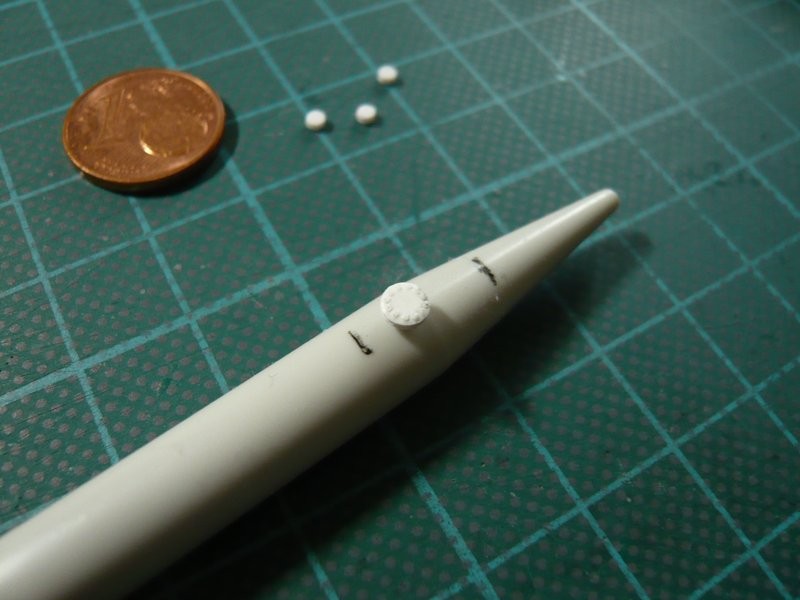 I think it's okay so far.
__________________
Greetings from Germany Manfred Under construction: Launch Pad 39A with Challenger STS-6 (1:144) Last edited by spacerunner; 04-07-2016 at 11:49 PM.
|
 |
|
|


 Linear Mode

