


|
|
|
#1241
 01-03-2017, 06:39 AM
|
||||
|
||||
|
Thanks Michael and a Happy New Year to you too with lots of fun and success in paper modelling and many prizes!!!
 
__________________
Greetings from Germany Manfred Under construction: Launch Pad 39A with Challenger STS-6 (1:144) 
|
|
#1242
01-06-2017, 04:26 PM
|
||||
|
||||
|
Hello everybody,
so friends, it is so far, now all 12 supports for the front outlets are finished, and I can once again breath deeply,  because I often had to hold my breath during handling the treacherous midgets in the tweezers to glue the gusset plates and fragile sickle holders. because I often had to hold my breath during handling the treacherous midgets in the tweezers to glue the gusset plates and fragile sickle holders. Now, here are the six supports behind the LOX-TSM, and on the right the six behind the LH2-TSM. 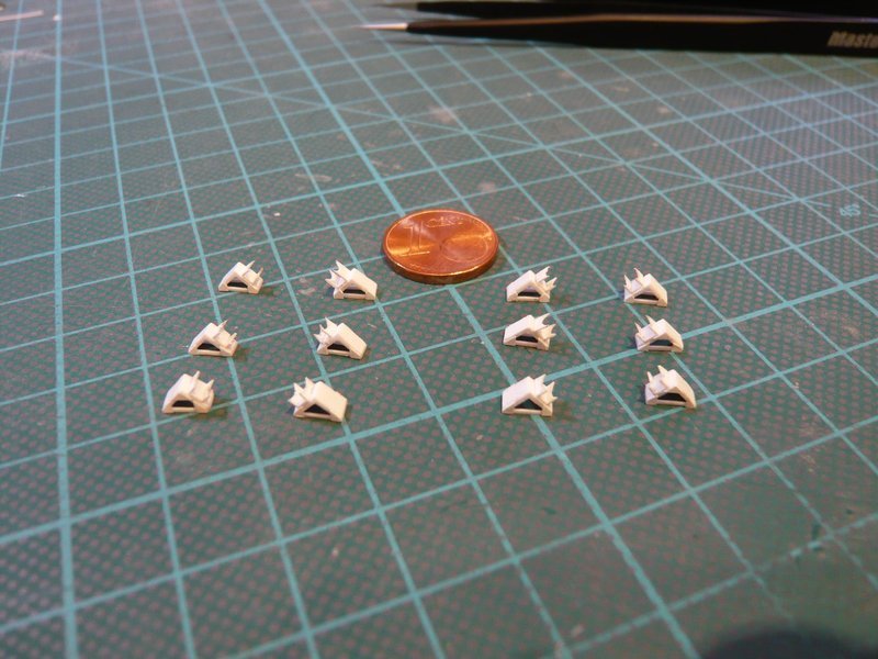 The next step was the test fitting of these 12 supports together with all the other supports of the SSWS, i.e. total of 52, which now gives an imposing picture.  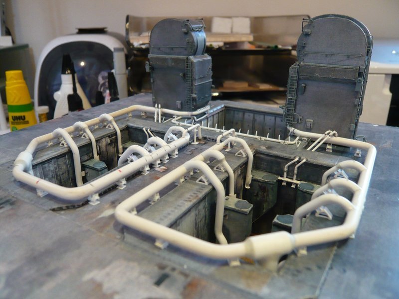 And to round off the picture, I have also added the Rainbirds again.  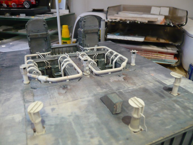 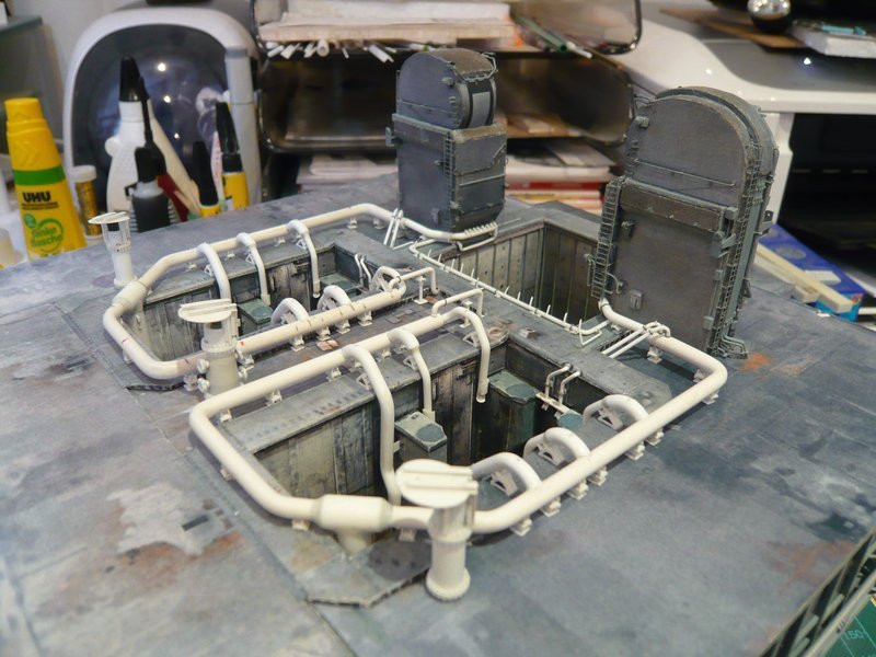 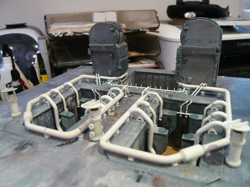 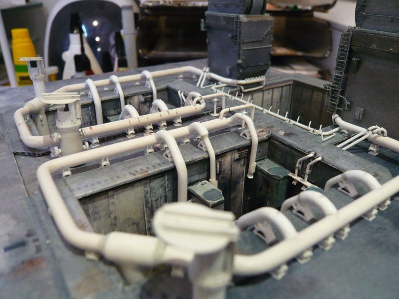 With the glueing of the supports on the two ring lines, I have to wait however still something, because before the the clamping rings have still to be attached, because afterwards would certainly be a little too stressful.  And these clamping rings want to be produced first, what will be again a tricky fiddling, whereby I want to use this time a different technique, which we had already discussed at some time earlier. 
__________________
Greetings from Germany Manfred Under construction: Launch Pad 39A with Challenger STS-6 (1:144)
|
|
#1243
01-13-2017, 02:38 AM
|
||||
|
||||
|
Hello everybody,
well, then let's go to the Clamping rings, there is no way to avoid it.  After I had read again in my building report from the midyear of 2015, I once again checked the different shapes of the screw connections of all clamping rings on the MLP-2. While the majority of the clamping rings are made up of six bolted ring segments, as shown on the right, there are also some, which consist of only four segments (on the left).   Source: NASA In this panorama image one can recognize the differences from a different perspective very well, and as one can see, the screw connections of the four-part clamping rings are somewhat longer than those of the six-part clamping rings. 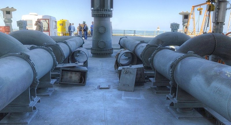 Source: NASA And with the aid of this picture, I had already determined the dimensions of the clamping rings and screw connections in those days, whereby the diameter of the 24" pipe (4 mm) was used as reference. 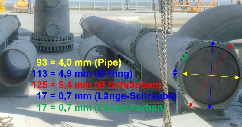 Source: NASA Since the image of my stock taking at the time seems to me to be somewhat overloaded from today's point of view,  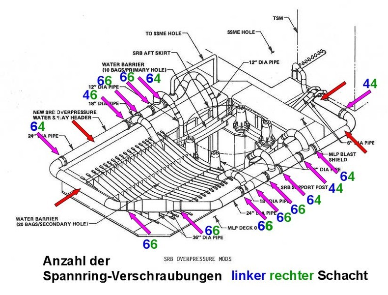 I have once again shown the number of screw connections of all clamping rings of both ring lines separately. In this case, the red arrows indicate the position of the supports, at which there are no clamping rings. Here first for the ratios at the ring line behind the LOX-TSM, 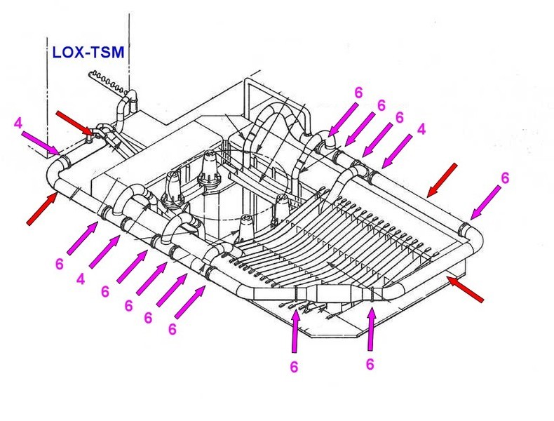 and here at the ring line behind the LH2-TSM. 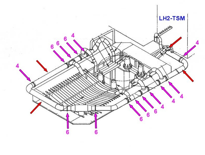 As one can see, the type of the clamping rings and the number of their screw connections is not identical on both sides.  After checking the dimensions again, I will use Evergreen Strips 0.38 mm x 0.5 mm for the six-part clamping rings and for the screw connections strips 0.25 mm x 0.75 mm, where 0,75 mm corresponds to the length of the screw connections. And for the somewhat longer screw connections of the four-part clamping rings I will probably use strips 0.25 mm x 1 mm. The construction of the clamping rings should be carried out accordingly to the lattice technique, which I have considered at the time. For this I first marked the distances of the screw connections on the peripheral length of both types, left for the four-part clamping rings and right for the six-part rings. Thereby the strips 0.25 mm x 0.75 mm (or 0.25 mm x 1 mm) for the screw connections are placed over parallel lying clamping ring strips 0.38 mm × 0.5 mm and glued with MEK, and subsequently separated. 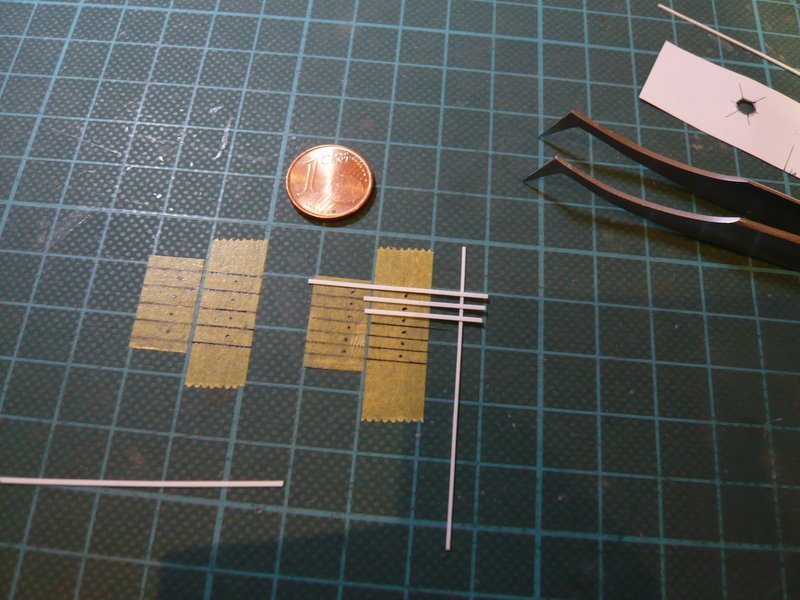 So far as the theory, next time prototypes of both types of clamping rings are to follow.
__________________
Greetings from Germany Manfred Under construction: Launch Pad 39A with Challenger STS-6 (1:144)
|
|
#1244
01-13-2017, 09:11 AM
|
|||
|
|||
|
The hint of your "building report" from previous years has me once again interested in the filing system and your documentation. While high praise is well earned for your construction Manfred, whatever your method of documenting this build and organizing it for later reference is a skill all unto its own!! You are a master sir!
|
|
#1245
01-13-2017, 12:38 PM
|
||||
|
||||
|
Agreed. Manfred you have earned a place of legend in the construction of this beast.
__________________
Non Sufficit Orbis-The world is not enough.
|
|
#1246
01-13-2017, 12:54 PM
|
||||
|
||||
|
Thank you my friends for your nice compliments and that you are speaking so glowingly about me and my work,
 what makes me proud and inspires me to continue my way as before. what makes me proud and inspires me to continue my way as before.
__________________
Greetings from Germany Manfred Under construction: Launch Pad 39A with Challenger STS-6 (1:144)
|
|
#1247
01-13-2017, 06:36 PM
|
||||
|
||||
|
Hello folks,
before I can start with the small series production, I have tried the first two prototypes of the clamping rings first without using the lattice technique, in order to see whether or how well the lengths and distances resulting from my templates will be okay. For this purpose, the four strips for the screw connections were positioned on the clamping ring strip (0.38 mm x 0.5 mm) and gently glued with MEK on both sides. 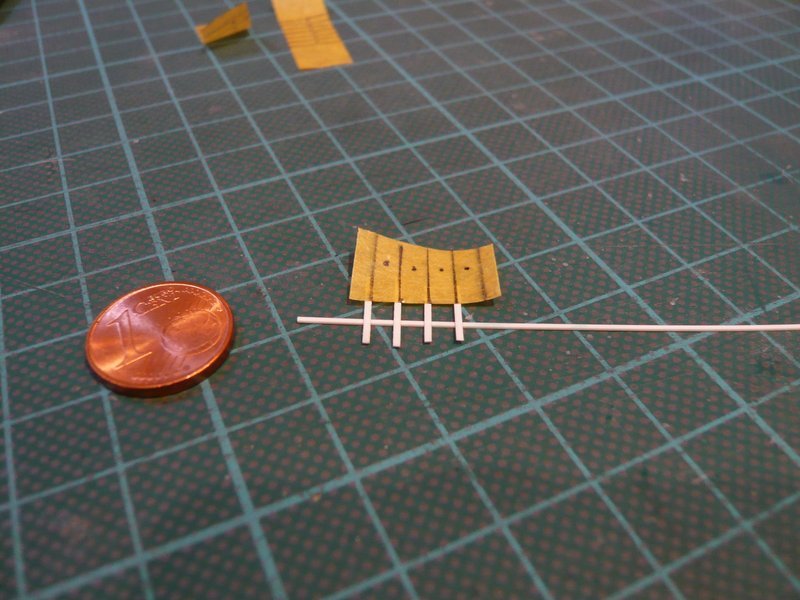 The strips then stuck so tightly that they could easily be cut off on both sides. 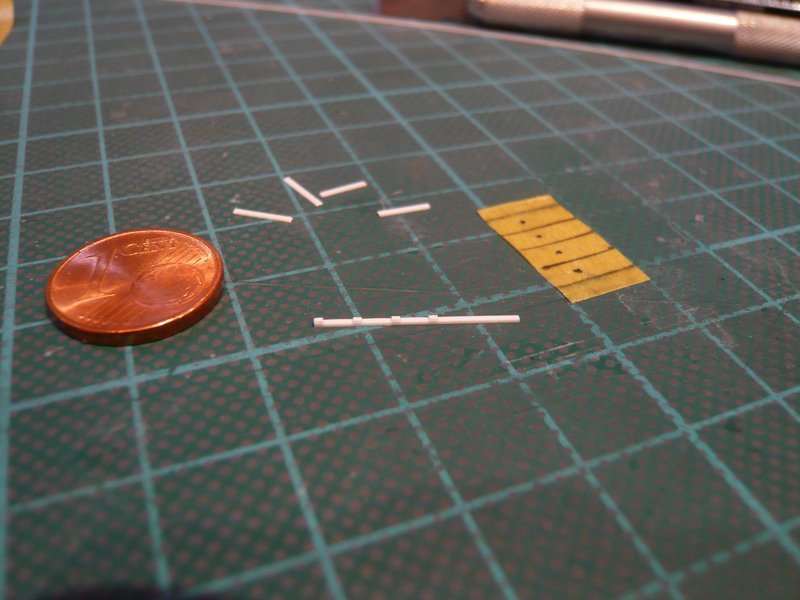 The gluing of the clamping ring on the 4 mm rod took place step by step with CA, because MEK is not suitable for this, which I had to observe unfortunately at that time, and I did not want to make the same disastrous mistake again.  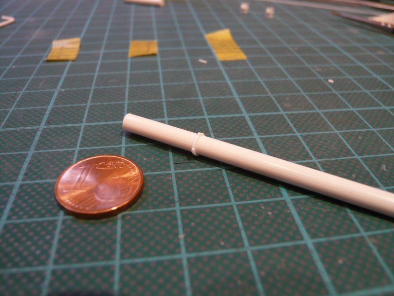 But only after I finished with this four-part clamping ring, it occurred to me that I had not used the wider strip (0.25 mm x 1 mm) for the screw connections, but the narrower (0.25 mm x 0.75 mm) for the six-part clamping rings.  But no matter, I have still noticed it in time. But no matter, I have still noticed it in time. After the same procedure, the six-part clamping ring was built, in which the screwing strips have moved closer together. 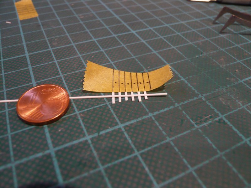 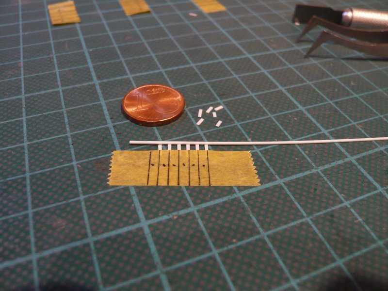 This time, too, everything went smoothly with the gluing of the strips, 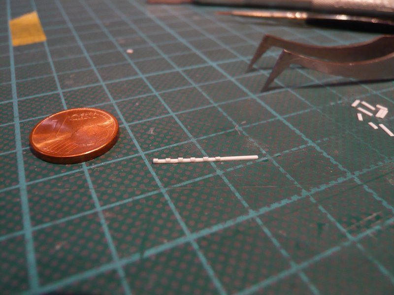 and here one can see both clamping rings next to each other. 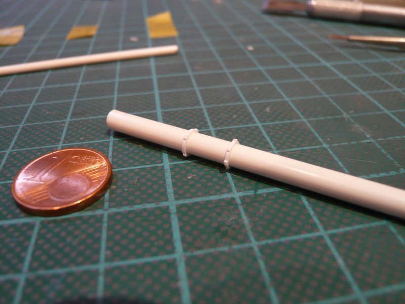 And so it looks then at the supports, wherewith I am for the time being quite satisfied. 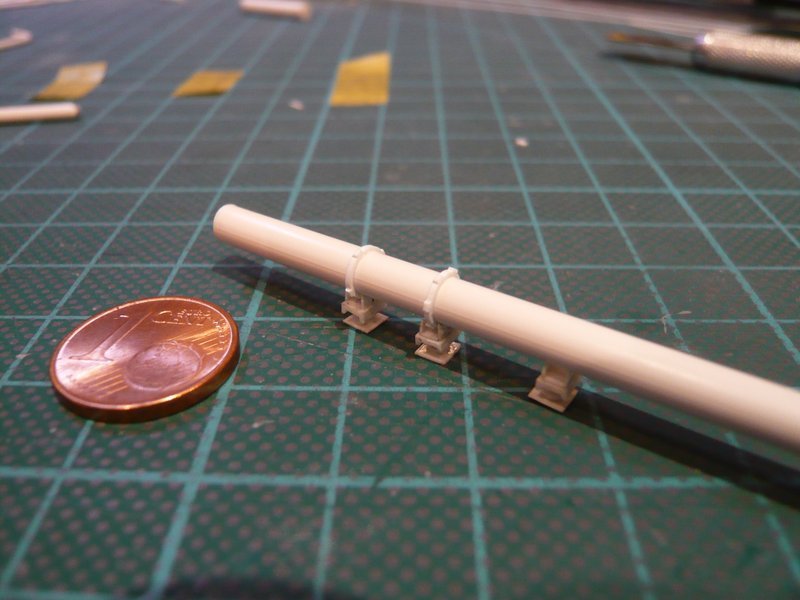 And if one would now round off the edges of the screw connections, it would look even more pleasant from near, which I have tried here at least once on the right clamping ring. 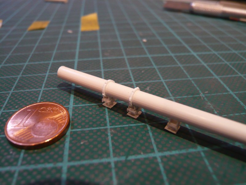 All other clamping rings I now want to scratch however after the lattice technique, for which I however need appropriate spacer. That's it for today.
__________________
Greetings from Germany Manfred Under construction: Launch Pad 39A with Challenger STS-6 (1:144)
|
|
#1248
01-14-2017, 05:06 AM
|
||||
|
||||
|
Hello everybody, here we go.
At first I've caught up the four-part clamping ring with the longer screw connections (1 mm), 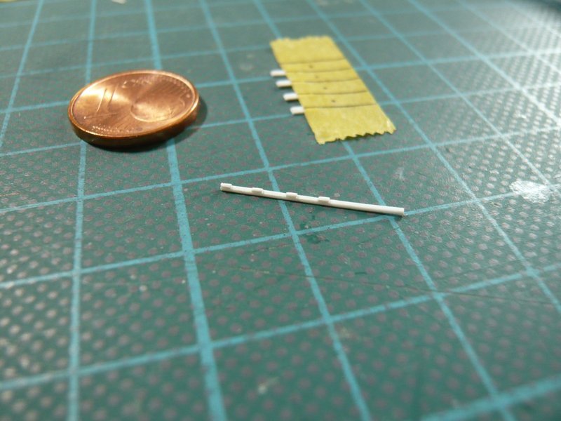 and compared it with the previous one with the too short screw connections (0.75 mm), the edges of which I have also rounded off somewhat. 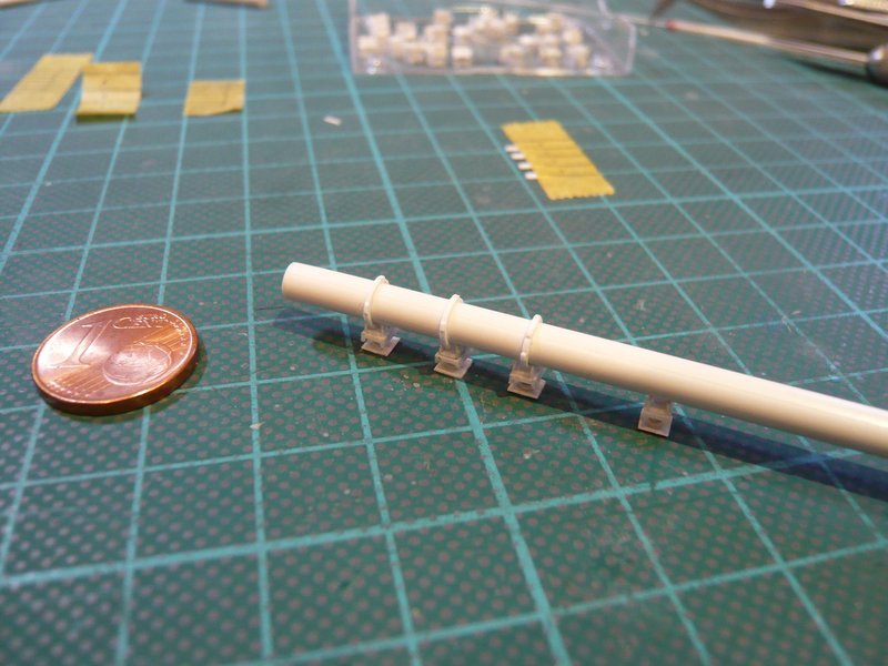 On this macro recording one can still recognize the difference, but from some distance probably already not more. And now to the small series of the nine four-part clamping rings, for which I wanted to apply the Lattice technique.  Originally I had also thought of a similar jig with spacers, as it had worked well for the cartridge belts of the Rainbirds.  But for these only nine clamping rings then I have renounced on it and have used only tapes. But for these only nine clamping rings then I have renounced on it and have used only tapes.  First of all I attached the strips (0.38 mm x 0.5 mm) for the clamping rings with the ends on a tape strip. 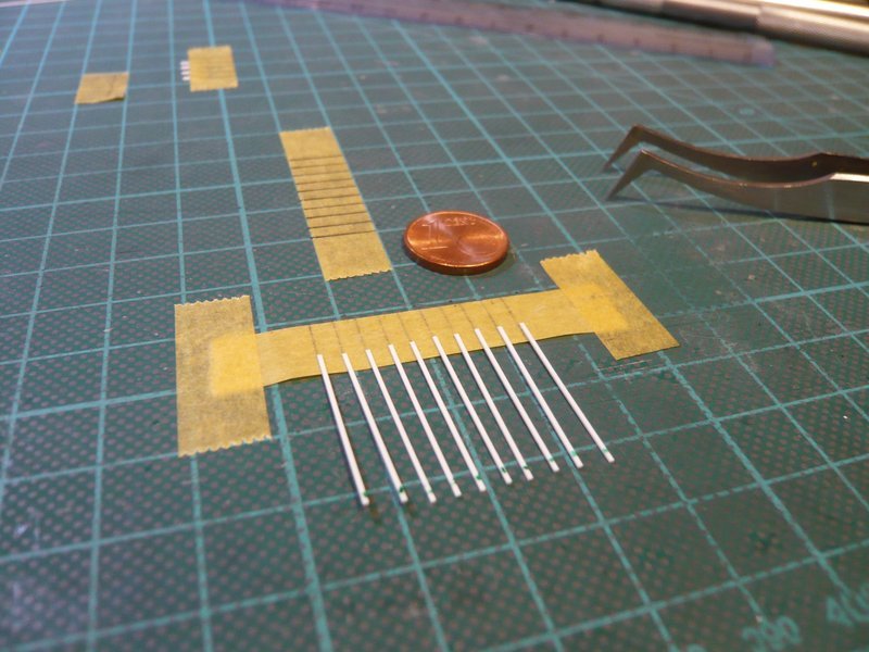 For bonding of the strips (0.25 mm x 1 mm) for the four screw connections per clamping ring with MEK, however, I have precautionally changed over to a metal sheet.  Then I have placed these four strips over the clamping ring strips and laterally fixed with tape. 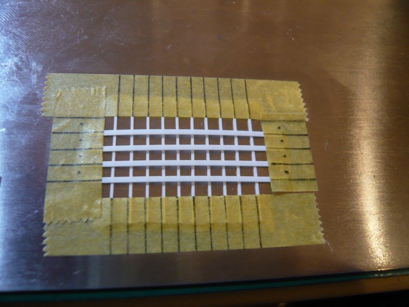 And in order for the screwing strips to lie tightly on top of each other during gluing, the lattice was still loaded by a weight. Afterwards, the superimposed strips on both sides were carefully dabbed with MEK, wherefore a brush tip MEK is really enough. 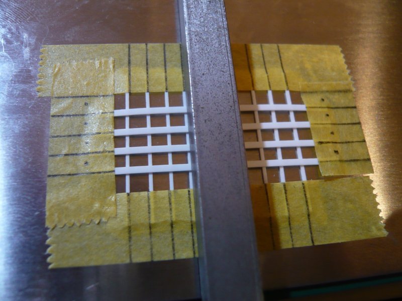 After the same gluing procedure was done on the back, the tape strips could be removed, and the clamping ring lattice was finished. 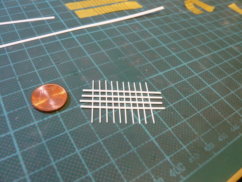 And lo and behold, the lattice is at first sight relatively stable, wherewith the lattice technique has proved itself. 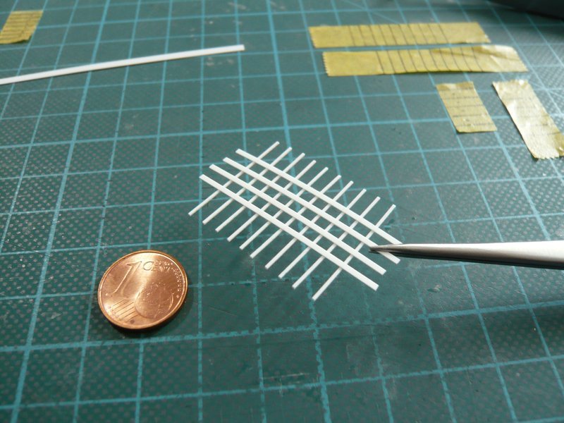 That's it for now, and next time the clamping rings will be separated.
__________________
Greetings from Germany Manfred Under construction: Launch Pad 39A with Challenger STS-6 (1:144)
|
|
#1249
01-15-2017, 04:43 PM
|
||||
|
||||
|
Hi everybody,
even if it is currently something tiring, here it goes on with the clamping rings, it is no good ...  Since the rounding of the edges on a single strip is quite difficult and obtently stressful, I have not completely separated the lattice, but only the outer overhangs are cut off. As a result, the outer side of the clamping ring, including the screw connections, can be rounded off relatively comfortably over the entire length since the lattice itself is surprisingly stable and flexible. 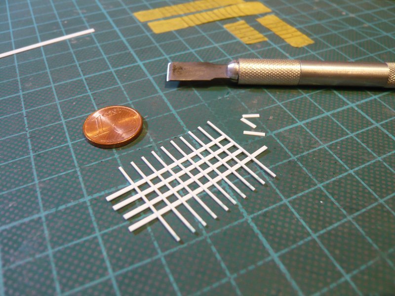 On the other side of the strip, one has to work carefully, particularly when rounding off the interstices,  for which I have made myself a 1.5 mm narrow grinding stick. for which I have made myself a 1.5 mm narrow grinding stick. 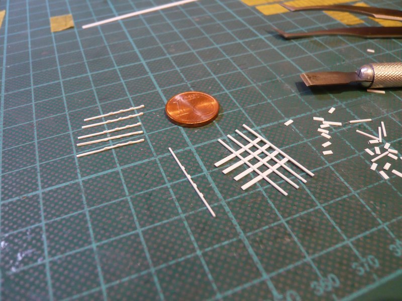 This business was very time-consuming, but then the nine clamping rings were finally (like myself) done. 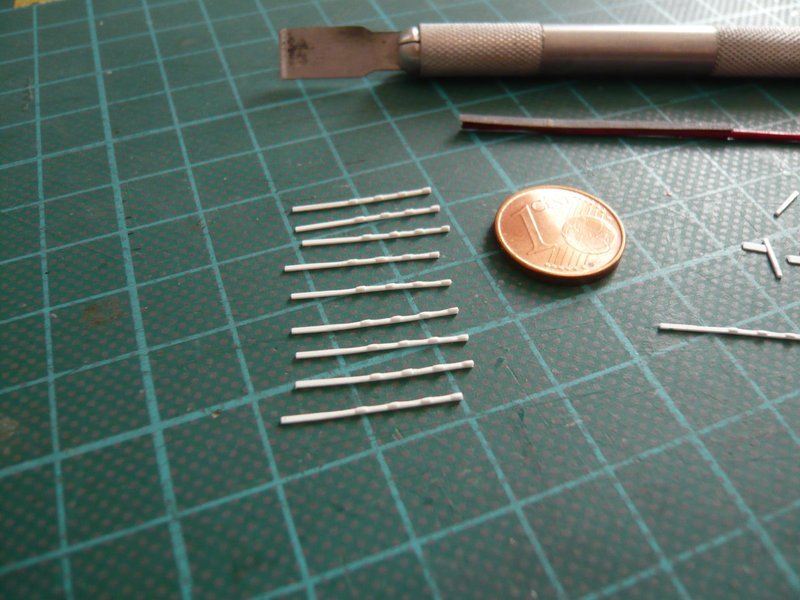 How good that I had planned a spare strip, because at one strip, during rounding off actually one screw connection was canceled.
__________________
Greetings from Germany Manfred Under construction: Launch Pad 39A with Challenger STS-6 (1:144)
|
|
#1250
01-16-2017, 05:56 AM
|
||||
|
||||
|
Hello everybody,
after the four-part clamping rings were securely stowed in a small box, I kept doing with the six-part rings, however 19 of them are needed. For the clamping rings 0.38 mm x 0.5 mm strips were again used, and 0.25 mm x 0.75 mm strips for the shorter screw connections. 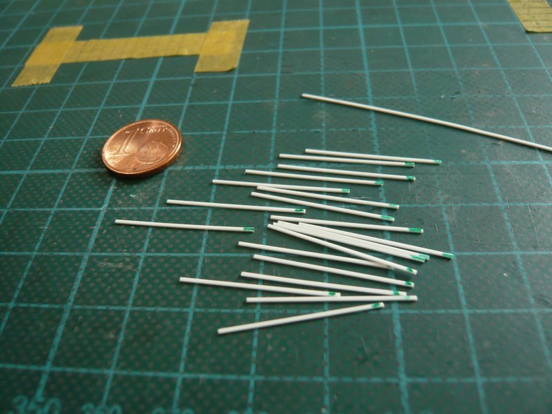 I will use the same method again to prepare two lattices each with 10 clamping rings, because the size had been okay. 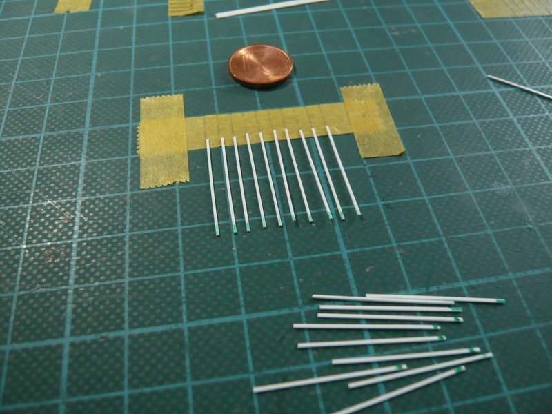 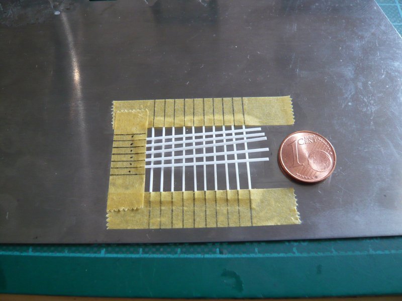 In order to hold down the screw connection strips, they had to weight again, 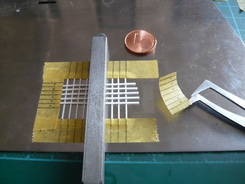 whereby I almost had forgotten one strip. 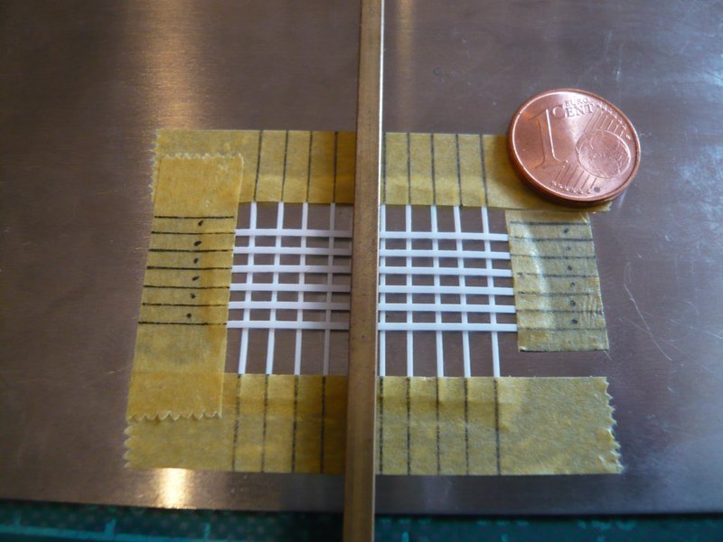 After the transverse strips were aligned once more, in order to have approximately equal distances, I have additionally two narrow masking strips glued, so that the lattice can not slip during MEK gluing. 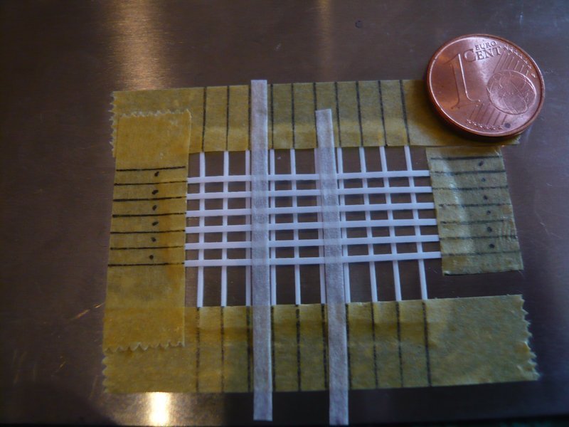 Then all the lattice junctions were glued together on the top side, 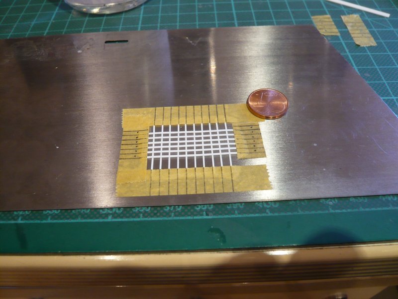 and then on the bottom. 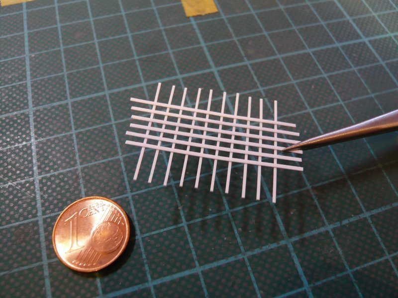 And with the first lattice again a small step was done, the next will follow soon.
__________________
Greetings from Germany Manfred Under construction: Launch Pad 39A with Challenger STS-6 (1:144)
|
 |
|
|


 Linear Mode

