


|
|
|
#1361
 06-01-2017, 08:09 PM
|
|||
|
|||
|
Thank goodness for that Manfred. Like Tonino I saw your model sitting on that high perch and my heart nearly stopped. At my age that's a Very Bad Thing. Most relieved to hear that it's safely back in its place.
__________________
This is a great hobby for the retiree - interesting, time-consuming, rewarding - and about as inexpensive a hobby as you can find. Shamelessly stolen from a post by rockpaperscissor 

|
|
#1362
06-05-2017, 03:34 AM
|
||||
|
||||
|
No more problem, now I also feel better again and can continue as if I had all the time in the world ...
 
__________________
Greetings from Germany Manfred Under construction: Launch Pad 39A with Challenger STS-6 (1:144)
|
|
#1363
06-10-2017, 08:48 AM
|
||||
|
||||
|
Hello friends,
now also the last fields on the Side 4 are newly re-glued, which looks now like new-born, 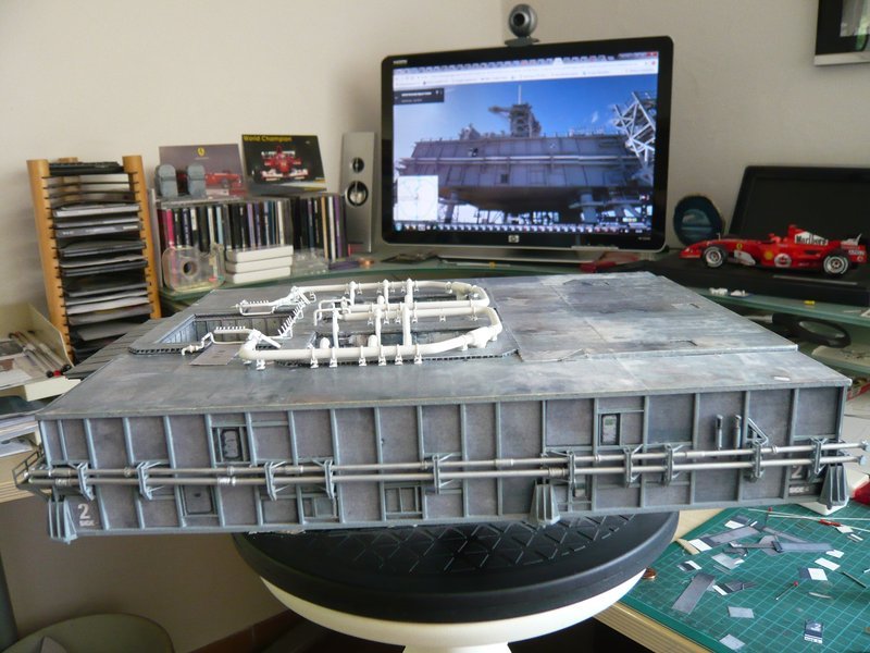 compared to the side from the paper kit 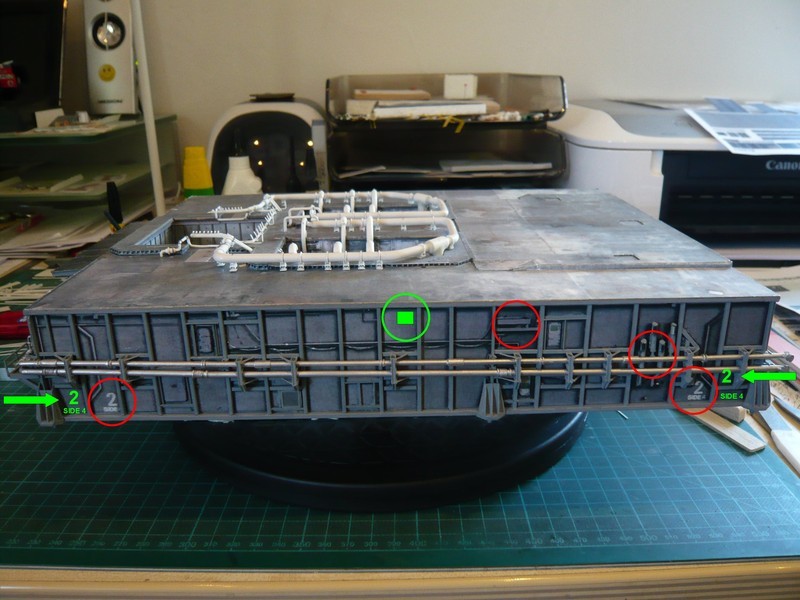 and only awaits their details.  And because we are dealing with cosmetic, I have attached the yellow markings on the LH2 Vent Line, seven in number, as can be seen on this image from the STS-8. 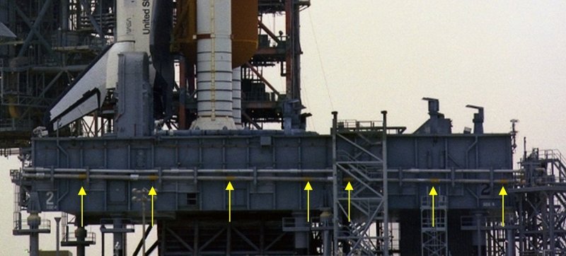 Source: NASA In order that the somewhat bulky little decals can easier cling around the pipe, I had to use Decal Soft again.  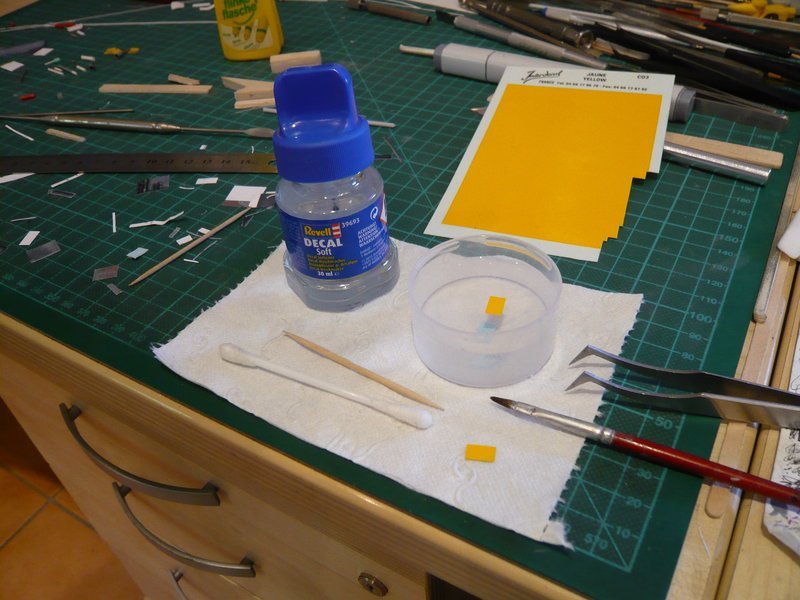 And that's how it looks on the MLP.  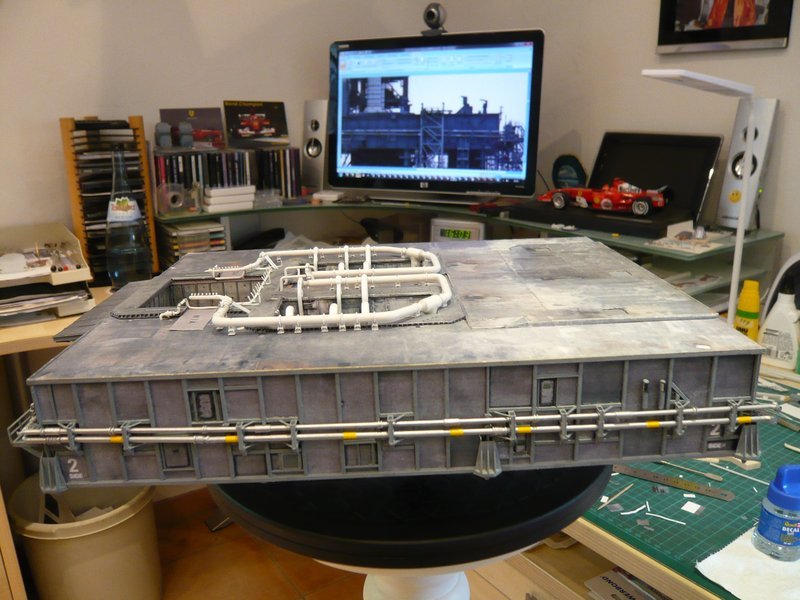 After the "renovation" of the side walls they look indeed a little bit bald, but now I could finally start with the detailing, first on the Side 2. I am still in the dark, which especially concerns the detail structure of this side during the STS-6, which does not make scratch-building easy.  I started with the through-sleeves and connecting sockets of the three ports for the ECS purge lines, 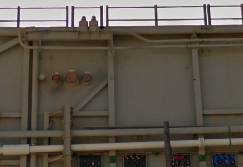 Source: NASA (Street View) for which I have separated 1 mm wide rings from the wire end ferrules, which protrude forward on the wall. The small connector to the left beside the downspout belongs to a GN2 pipe, the front of which looks like a handwheel and also sits in a through-sleeve, what I then have tried to scratch laboriously.  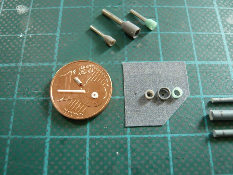 The sleeve is a piece of a wire end ferrule (Ø 1 mm) and the wheel is from a section of a rod (Ø 1 mm), which I tried to slit all around with the cutter.  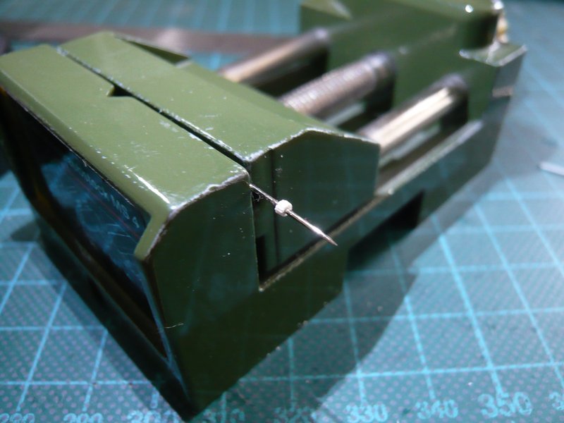 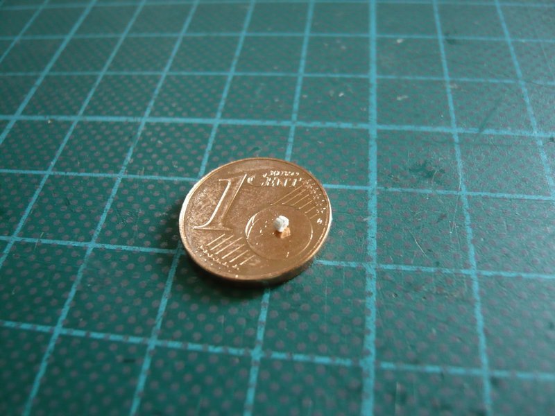 On the right lay the round bars for the connecting sockets. 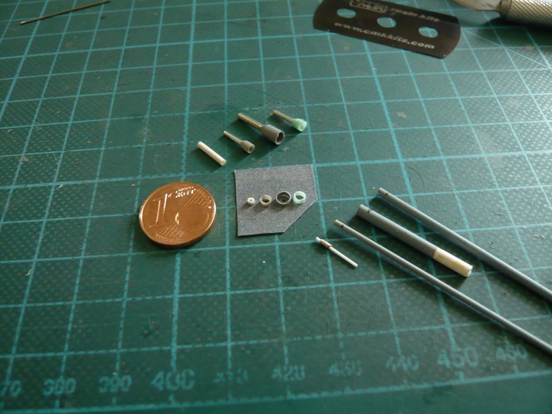 And so this part in the sleeve looks so far, an attempt was worth it at any rate.  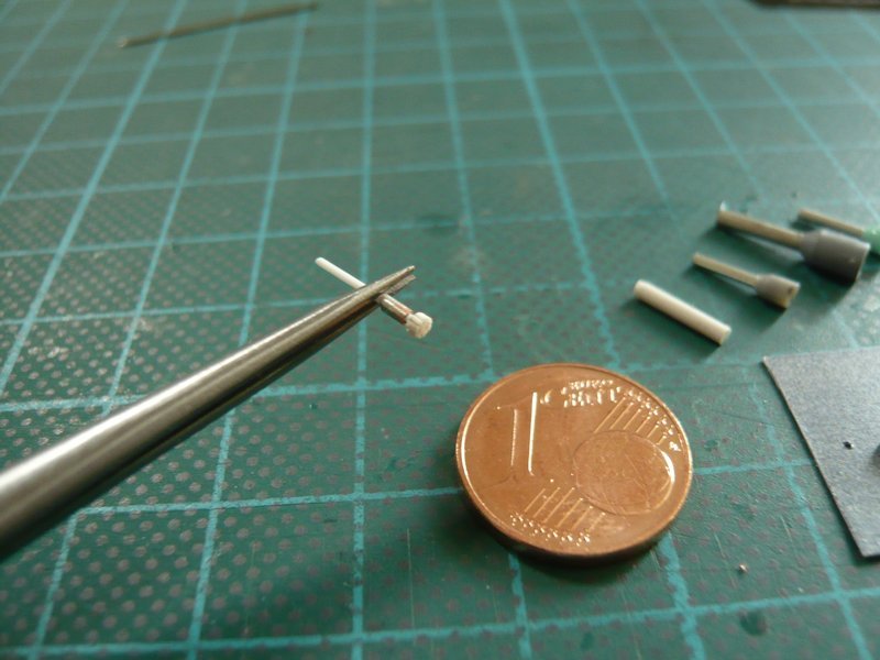
__________________
Greetings from Germany Manfred Under construction: Launch Pad 39A with Challenger STS-6 (1:144)
|
|
#1364
06-10-2017, 09:30 AM
|
|||
|
|||
|
How can it get any better? it does with each and every new photo.
|
|
#1365
06-11-2017, 05:12 PM
|
||||
|
||||
|
Thanks for your nice compliment,
 I'm glad if you like what I'm doing here and will give my best.
__________________
Greetings from Germany Manfred Under construction: Launch Pad 39A with Challenger STS-6 (1:144)
|
|
#1366
06-19-2017, 05:13 PM
|
||||
|
||||
|
Hello everybody,
next I tried to paint the caps of the connecting sockets red, first times with two test rods. 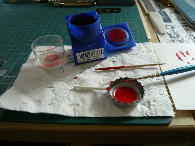 Since the lengths of the caps with the brush by hand are not to manage with uniform lenght, I have masked the rod tops accordingly. 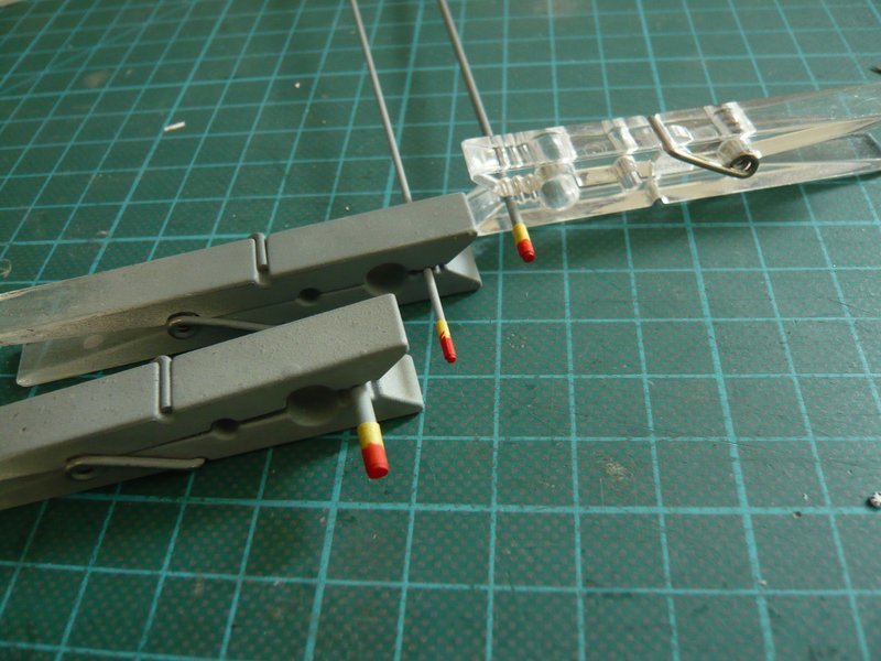 And now it looks better, to the left is a second variant of the handrail, which has only a thin disc at the front, which corresponds more to the real part, which is more likely a blind flange, 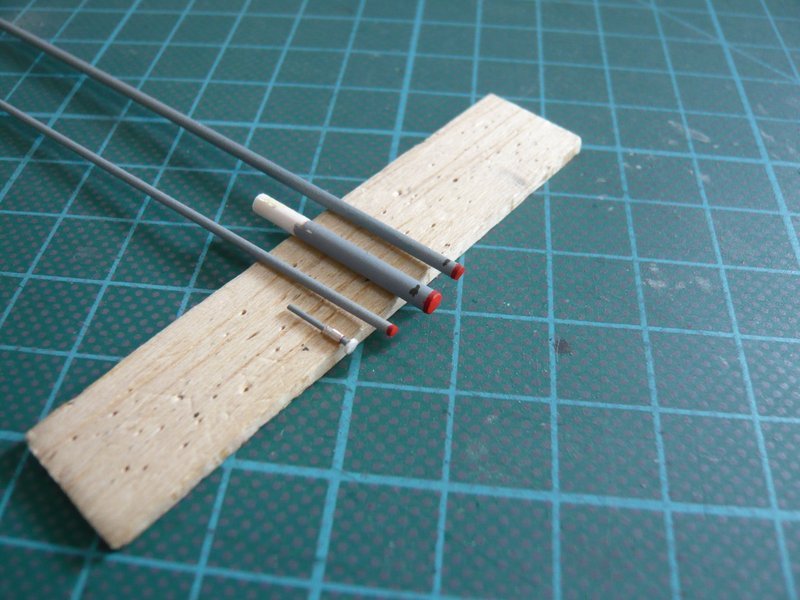 as I have now found out. 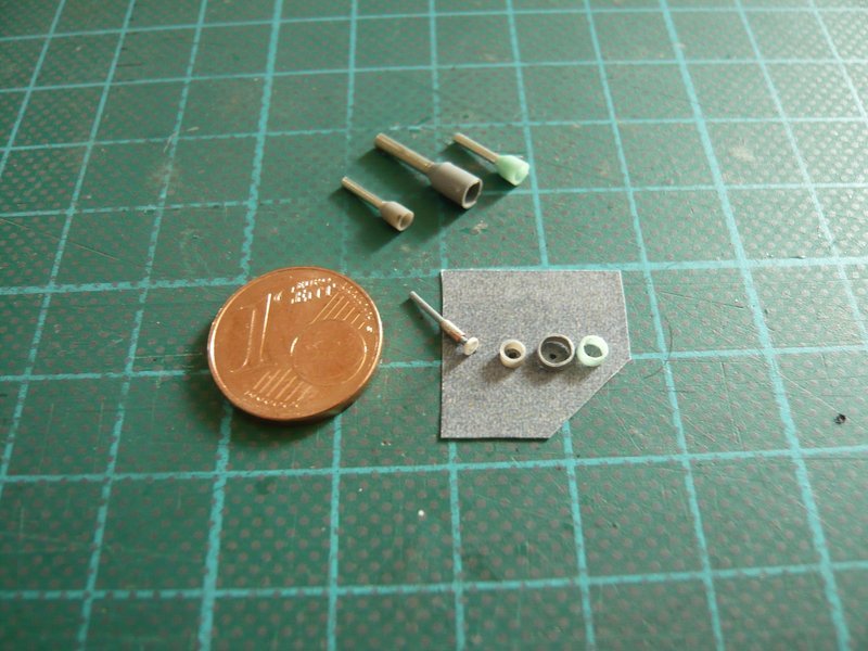 Since I would like to paint the small through-sleeves by Airbrush, I have pinned the parts on my Balsa-Holding strip, which I had used for the lampshade lacquer. 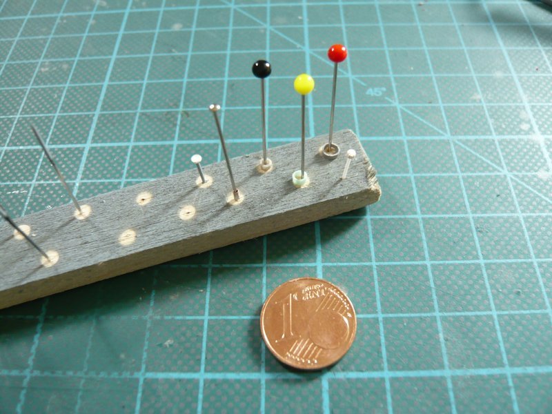 And in this airbrush job, also a few profiles for the pipes on the side walls will be sprayed, which I have already prepared. 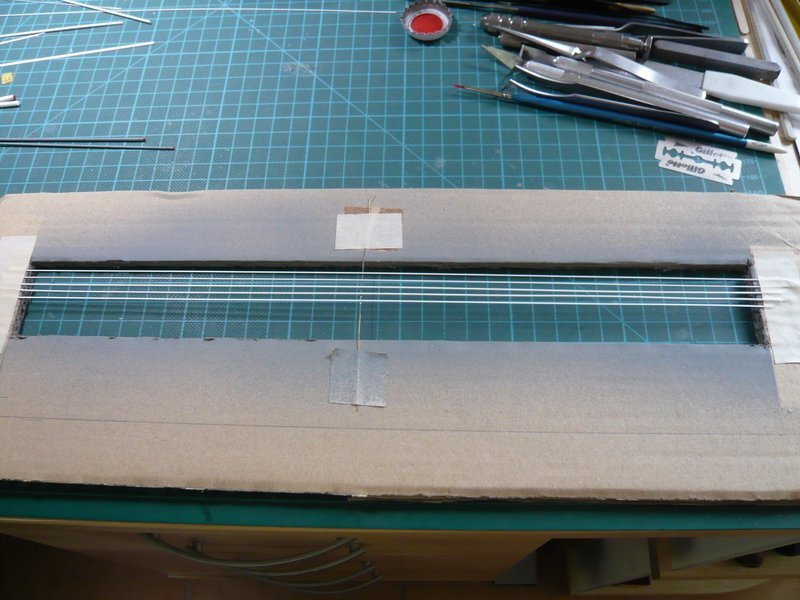 These are, inter alia, the two lines with the double kink, 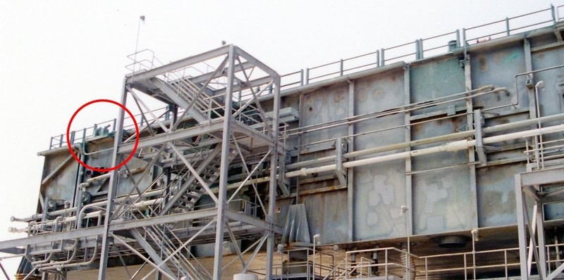 Source: apollosaturn.com (John Duncan) whose connection on this console with the two attachments was a mystery to me until now.  In the meantime, NASA has also digitized the photos contained in the so called MLP-Report and made them available online, from which I have already taken a lot of detailed information. And these reference photos (unfortunately only black and white) are predestined for detail studies because of their high resolution.   Source: Library of Congress In addition to this image as JPEG (316 KB), on which one can not see enough details, there is also a huge TIFF format (38 MB),  on which one can clearly see that the two pipes are actually connected to these two attachments, which I had so far only suspected. And on this image one can also see that the front part on the GN2 Line is probably a blind flange. on which one can clearly see that the two pipes are actually connected to these two attachments, which I had so far only suspected. And on this image one can also see that the front part on the GN2 Line is probably a blind flange. 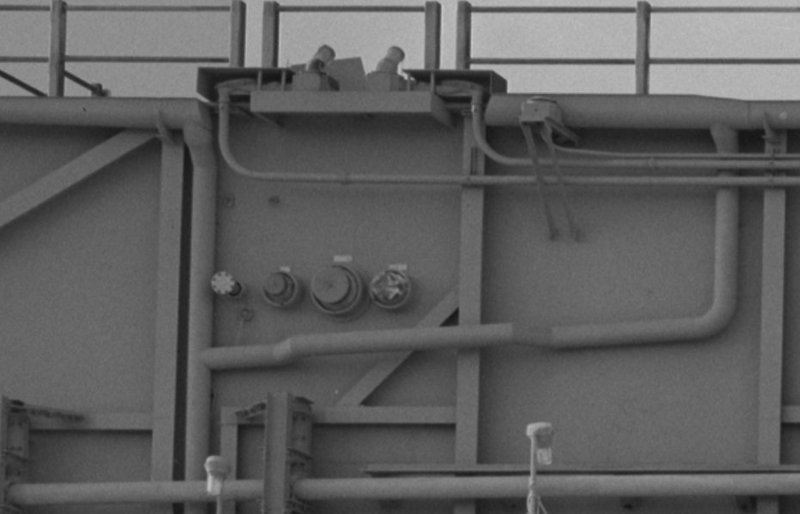 Source: Library of Congress This version of the connectors with the covers is only available on the MLP-3, on the MLP-2 they are missing , as one could already see on this earlier image. 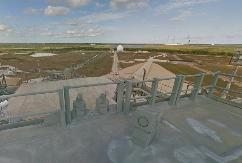 Source: NASA (Street View) In any case, similar connector caps are located in front of the attachments, as can be seen from this perspective. 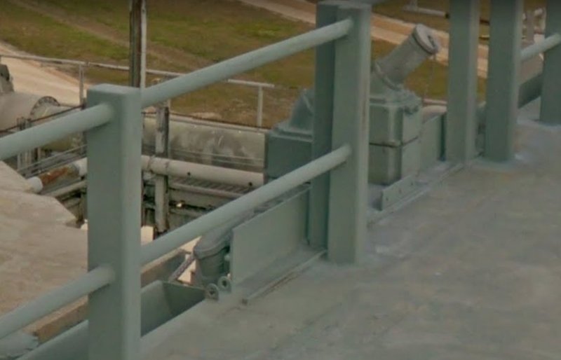 Source: NASA (Street View) That this connection console was still slightly different on the MLP-1, can be seen in this image. Source: NASA (Street View) The MLP-Report contains, among other things, also a drawing of the Side 2 from which this image section comes, from which I have determined the dimensions of the box (Fire Hose Reel). 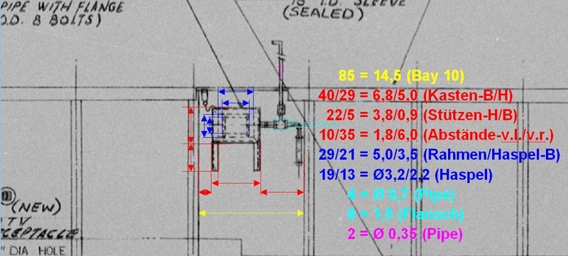 Source: Library of Congress And these are the prepared parts for the box of 0.3 mm Styrene with two support struts (0.5 mm x 1 mm), whereby I assume that these were more likely angle profiles, for which I could use an already painted brass profile (1 mm x 1 mm). 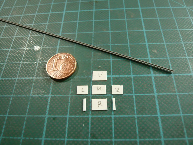 So much for the theory, which I now only need to put into action.
__________________
Greetings from Germany Manfred Under construction: Launch Pad 39A with Challenger STS-6 (1:144)
|
|
#1367
06-19-2017, 05:23 PM
|
||||
|
||||
|
Hello everybody,
here still a short flash from a first attempt to bend the two thin pipes. For this I have used copper wire Ø 0.6 mm and a copy of the Side 2 of the MLP-3 as bending template, which is why I had to correct the double kink a little bit. 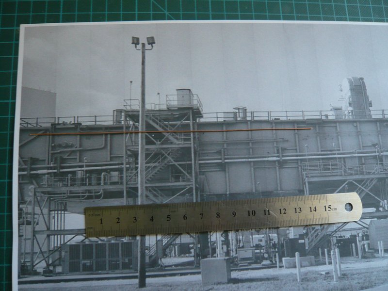 And these are the two pipes in the raw state, from which the left ends are now adapted to the attachments on the console and the right ends must be shortened and angled. 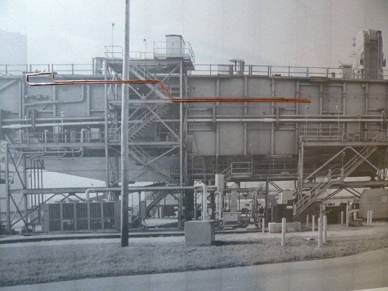 Sorry, but the light conditions are unfortunately not the best. And thus to the next pipe on this side, whereby I assume that it is a Firex line. The same line there is also on the Side 4, to which we will come later. This pipe is a bit thinner than the first two pipes, it starts somewhere in Bay 13 and then it takes the marked course to the front corner of Side 2,  Source: NASA Since on this image one can recognize the beginning of the line unfortunately just as little as on this image of the MLP-2, 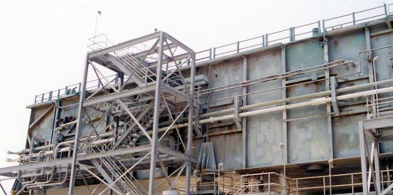 Source: apollosaturn.com (John Duncan) I have consulted again the Street View panorama of the MLP-1. And here I have found a suitable perspective, on which one can recognize,  that the line comes out of the wall of the lower MLP-B Level to the right of the door and then runs first to the top and then to the right. that the line comes out of the wall of the lower MLP-B Level to the right of the door and then runs first to the top and then to the right.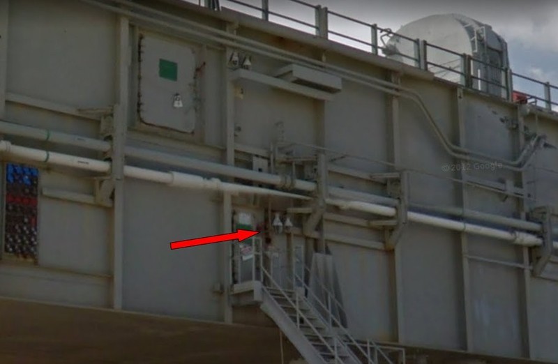 Source: NASA (Street View) Compared to the first two pipes (Ø 0.6 mm), this line should have a diameter of 0.4 mm, for which I also used Cu wire. And here the test line is temporarily layed down, but at the lower end it must be shortened and angled. 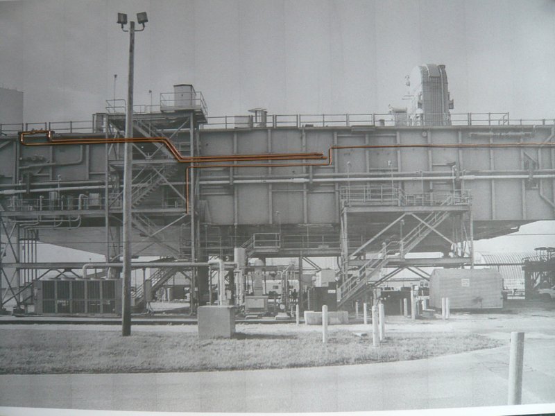 At the other end of the line at the front corner to the Side 1, I was initially not quite clear about their real run during the STS-6, provided that it already existed at that time. As can be seen in these images from John Duncan's collection (1998), the line runs around the corner to the Side 1, 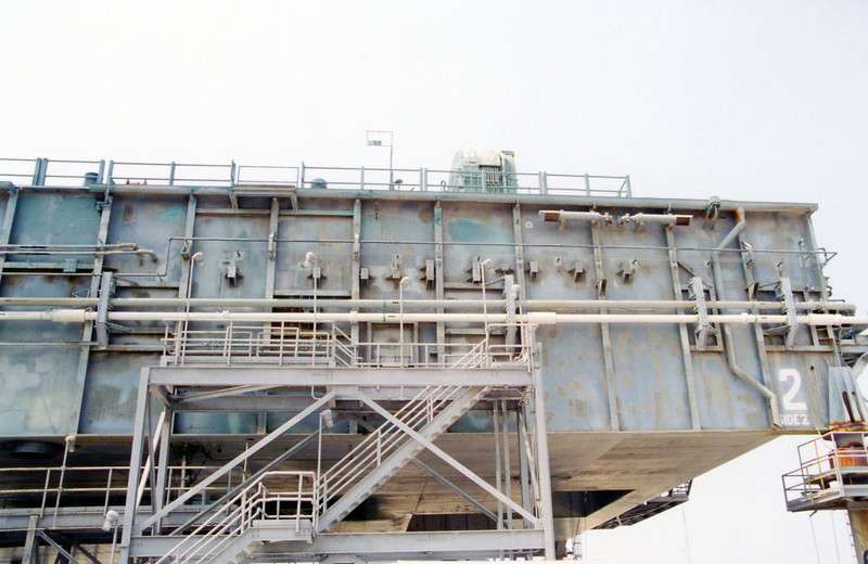 Source: apollosaturn.com (John Duncan) and flows then in the thicker Firex main line, which is running under the Blast Shields to the other end of the side and then on Side 4, where it ends in Bay 13. 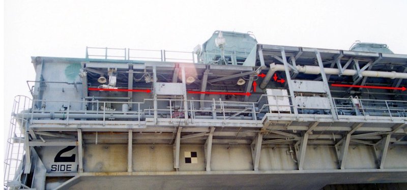 Source: apollosaturn.com (John Duncan) And now comes the surprise, .On my standard reference image of the STS-6 one can see that there was no continuation of this Firex line behind the corner on the Side 1, maybe it was extended only later up to the main line, but it is only questionable when, respectively whether at all?  Obviously, there is something else, whereat the red arrow points, to what I'll come back later. [ 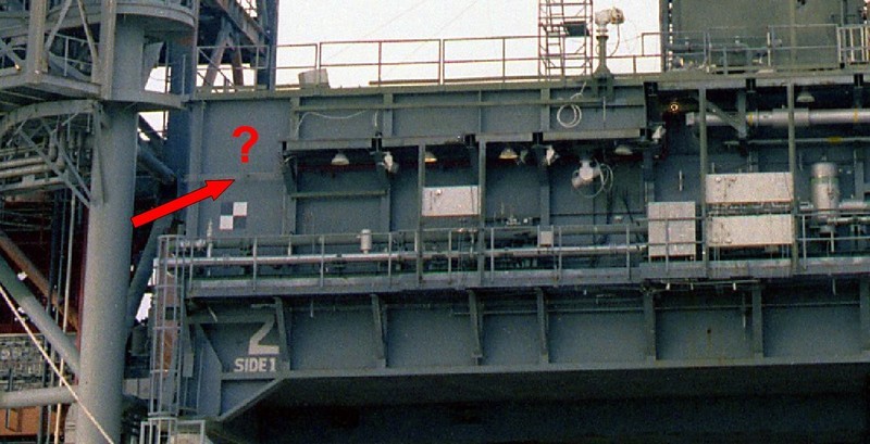 Source: retrospaceimages.com (STS-6) To the right side of the Side 1 it looks similar, where the red Firex main line ends in front of the corner and only some cables run around the corner. 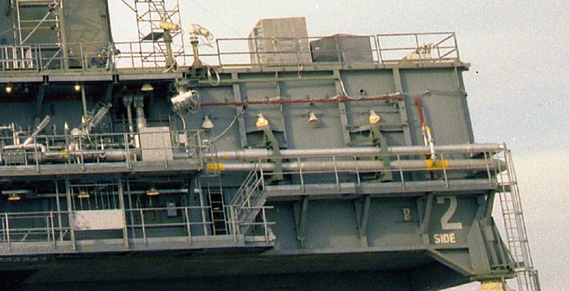 Source: retrospaceimages.com (STS-6) And so I have arrived at a point where I have to rethink everything, because that would mean that I can save myself the thinner pipe apparently, because it still did not exist at that time presumably.
__________________
Greetings from Germany Manfred Under construction: Launch Pad 39A with Challenger STS-6 (1:144)
|
|
#1368
06-19-2017, 05:26 PM
|
||||
|
||||
|
Hello everybody,
well, so is it with the details, which I wanted to start scratching, but which on closer inspection suddenly vanish into thin air ...  Therefore it is absolutely necessary to take care to the mission they are based on and whether they are relevant to the own mission. But that I did not keep in mind at John Duncan's MLP-2 images of 1998, because I was so thrilled about their details, a typical case of Not a bit of it! Therefore it is absolutely necessary to take care to the mission they are based on and whether they are relevant to the own mission. But that I did not keep in mind at John Duncan's MLP-2 images of 1998, because I was so thrilled about their details, a typical case of Not a bit of it!  Afterwards one is unfortunately always smarter, but aside from the STS-1, there are relatively few usable Hi-Res images from the first missions, especially from Side 2, where it unfortunately looks gloomy. That's why I took the trouble and have specifically investigated the first [color= blue]MLP-2 missions[/color] until the end of the 80s once again, finally to get information about these ominous Firex Lines. And these were the following missions: Challenger: 1983: MLP-6, MLP-8, 1984: STS-41B, 1985: STS-51B, STS-51F, 1986: STS-51L; Discovery: 1984: STS-41D, STS-51A, 1988: SSTS-26; Atlantis: 1985: STS-51J, STS-61B. And in doing so, I found out, that 1983 during the first missions, there was no transition of the Firex line from the Side 2 to the Side 1, but first in 1984 at the Challenger mission STS-41B, as one can clearly see in this image, especially with zoom.  Source: NASA At the previous mission STS-8, this transition did not yet exist, as one can see on this image unfortunately not so sharp, but nevertheless.  Source: NASASpaceFlight.com Forum What one can see as a shadow is the detail (?) on MLP-2, what I've already mentioned in the last post, which I will now still examine carefully.  And therefore back to the Side 2 of the MLP-2 (1998), on which one can see it also only schematically in the zoom.  Source: apollosaturn.com (John Duncan) These are actually four thin Fuel cell pipes (Ø 0.5'' = 12.7 mm) for the fuel cells of the orbiter, namely the two upper GO2 pipes and the two lower GH2 pipes. More clearly, this bundle is seen on this image from the MLP-2 at the STS-132.  Source: NASA If one really wanted to scratch these four pipes, one would need wires with a diameter of about 0.1 mm,  which I have procured some time ago. which I have procured some time ago. BTW, here is such a wire (Ø 0.1 mm) in cosy togetherness with a hair (Ø 0.05 mm) of mine, 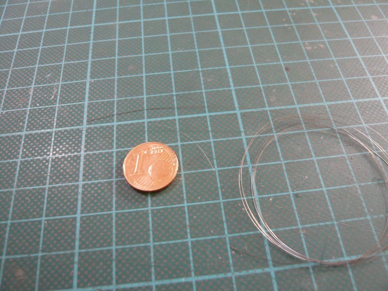 whose color however will not be betrayed.
__________________
Greetings from Germany Manfred Under construction: Launch Pad 39A with Challenger STS-6 (1:144)
|
|
#1369
06-19-2017, 06:12 PM
|
||||
|
||||
|
I remember seeing Challenger on the pad in 83. We took the bus tour that circled the pad slowly and then they let us out about 2 miles from the pad along the crawler-way to take photos. If I took any pictures back then, I'm sure they didn't turn out too great since all I had was a cheapie 110. But I'll never forget that bus ride!

|
|
#1370
06-20-2017, 12:32 AM
|
||||
|
||||
|
Lucky you!
I can understand you well, these are everlasting memories that one will never forget.
__________________
Greetings from Germany Manfred Under construction: Launch Pad 39A with Challenger STS-6 (1:144)
|
 |
|
|


 Linear Mode

