


|
|
|
#2011
 10-25-2019, 06:14 PM
|
||||
|
||||
|
I was thinking about you Tuesday....... as I passed the cleaning tank at my dentist's office!


|
|
#2012
10-26-2019, 12:35 AM
|
||||
|
||||
|
Thanks Becky for remembering on me.
 Maybe you had this picture in mind,  when my 3D Intertank was splashing in the Ultrasonic cleaning bath of the nice guys from ChiliDent ...  
__________________
Greetings from Germany Manfred Under construction: Launch Pad 39A with Challenger STS-6 (1:144)
|
|
#2013
10-26-2019, 04:02 PM
|
|||
|
|||
|
Absolutely insane! Welcome back, Mani!!! I have missed you and I am very glad that you have found a way to be here again.
|
|
#2014
10-26-2019, 04:37 PM
|
||||
|
||||
|
Thanks Marcell,
I'm very glad too, that we found a way out, and therefore the show can go on!!! 
__________________
Greetings from Germany Manfred Under construction: Launch Pad 39A with Challenger STS-6 (1:144)
|
|
#2015
10-26-2019, 04:44 PM
|
||||
|
||||
|
Hello everybody,
and today the new GH2 Press. Line made of Nickel silver wire (Ø 0,4 mm), which is bent even more precisely, whereby it can easier cling to the Cable Tray and around the LH2 Feedline.  Bending the wire was a bit more difficult, as the Nickel silver wire is less ductile than the Copper wire, but after a few tries it went smoothly. Bending the wire was a bit more difficult, as the Nickel silver wire is less ductile than the Copper wire, but after a few tries it went smoothly.  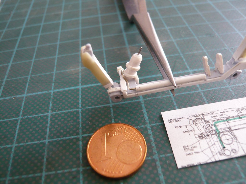 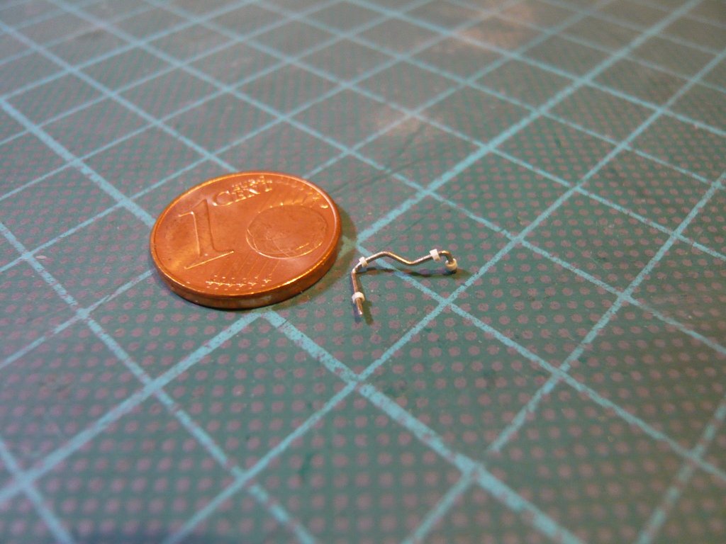 And also with the Fittings from insulating hose the line fits well.  When inserting, I always put the long end first in the opening in the Umbilical plate, 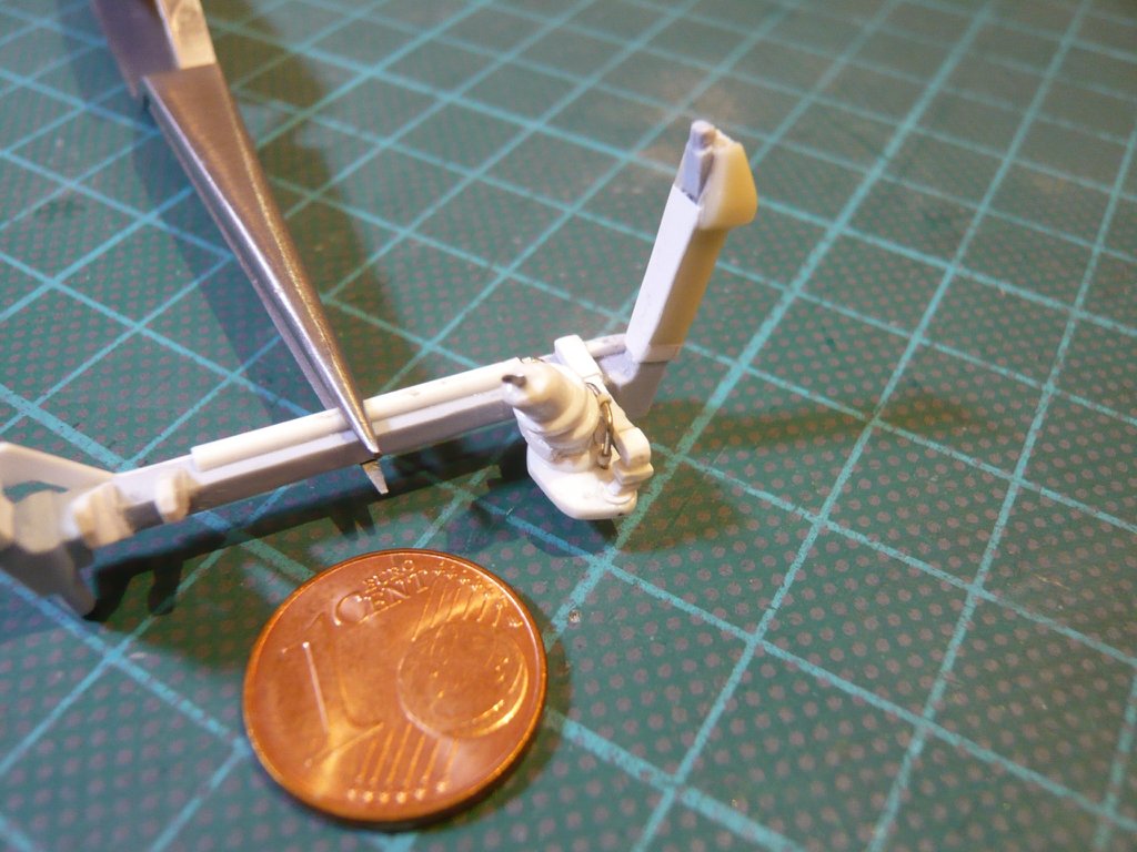 and then the front end into the in die TPS cladding of the Press. Line.  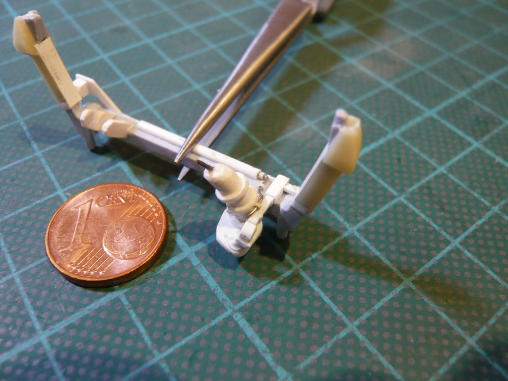 This allows me to paint the line separately and then finally insert it. 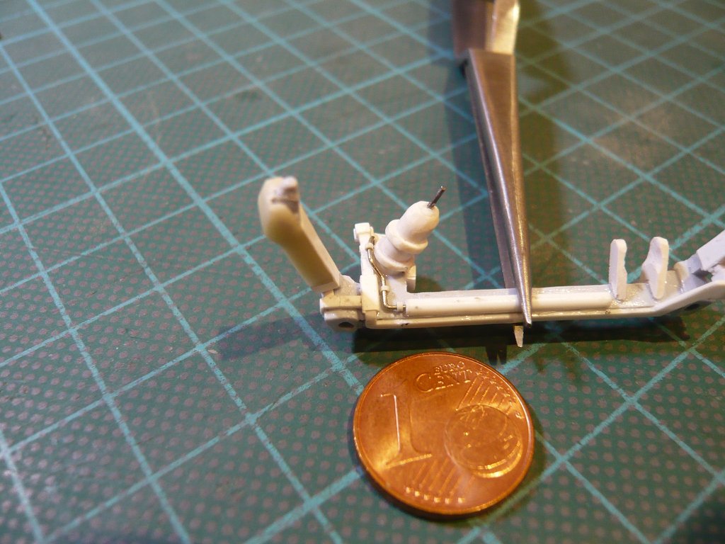 After that the LH2 Umbilical is done, I can go on with the LO2 Umbilical on the other side, where again the Cable Tray with the Supports has its turn.
__________________
Greetings from Germany Manfred Under construction: Launch Pad 39A with Challenger STS-6 (1:144)
|
|
#2016
10-27-2019, 03:18 PM
|
||||
|
||||
|
Hello everybody,
so then let's go to the LO2 Umbilical, which can be seen from behind especially in the zoom in all its beauty.  Source: NASA Observing from the front, it is noticeable that at the LO2 Feedline there is still this special Support, which is rather thin and sits directly below the LH2 Cable Tray on the Crossbeam.  Or maybe it's a part of the TPS Cladding of the Umbilical. Or maybe it's a part of the TPS Cladding of the Umbilical.  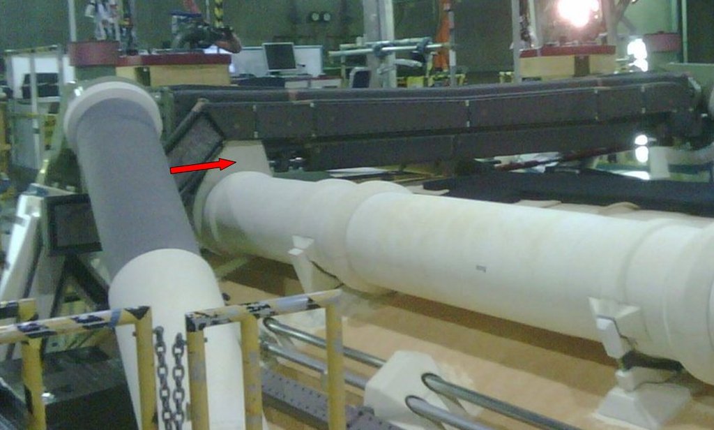 Source: forum.nasaspaceflight.com (DDG40) For the further separate construction of the ET/Orbiter Attachment, I have considered that it would be better to cut off the LO2 Feedline at this point and to glue the back bow with the LO2 Umbilical plate between the two Support Brackets and then to glue the thin support onto the front end of the bow. Then the other Support/TPS parts and the LO2 Cable Tray as well as the end of GO2 Press. Line will be installed. The front part of the Feedline is too short anyway and has to be extended up to the Fairing on the Intertank. And only after the Flour coating process and painting of the ET all lines including the Ice Frost/PAL Ramps as well as the complete ET/Orbiter Attachment will be installed on the tank. 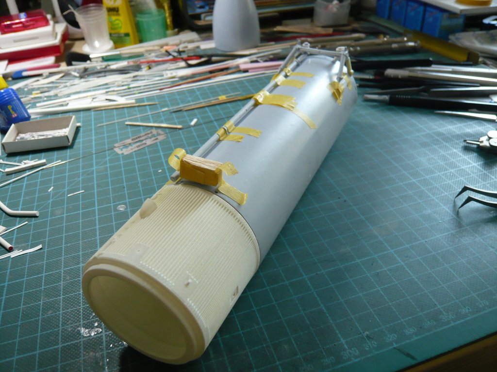 Before cutting through the Feedline I first had to find out the geometry and the dimensions of the Support-Plate, which was not that easy, because the parts are only temporarily attached.  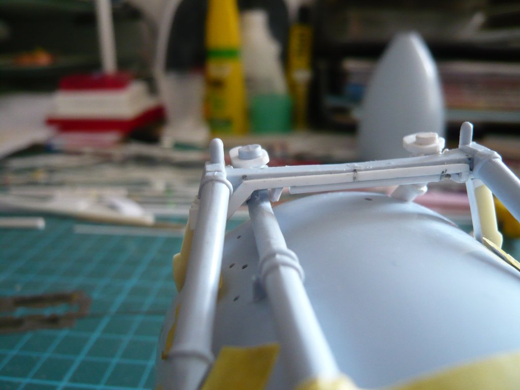 With the measured distance between Feedline and Cable Tray of approx. 2 mm I drew this little sketch, 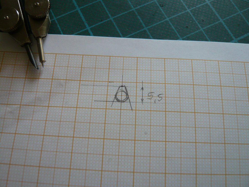 which I then transfered to Styrene (0,5 mm), 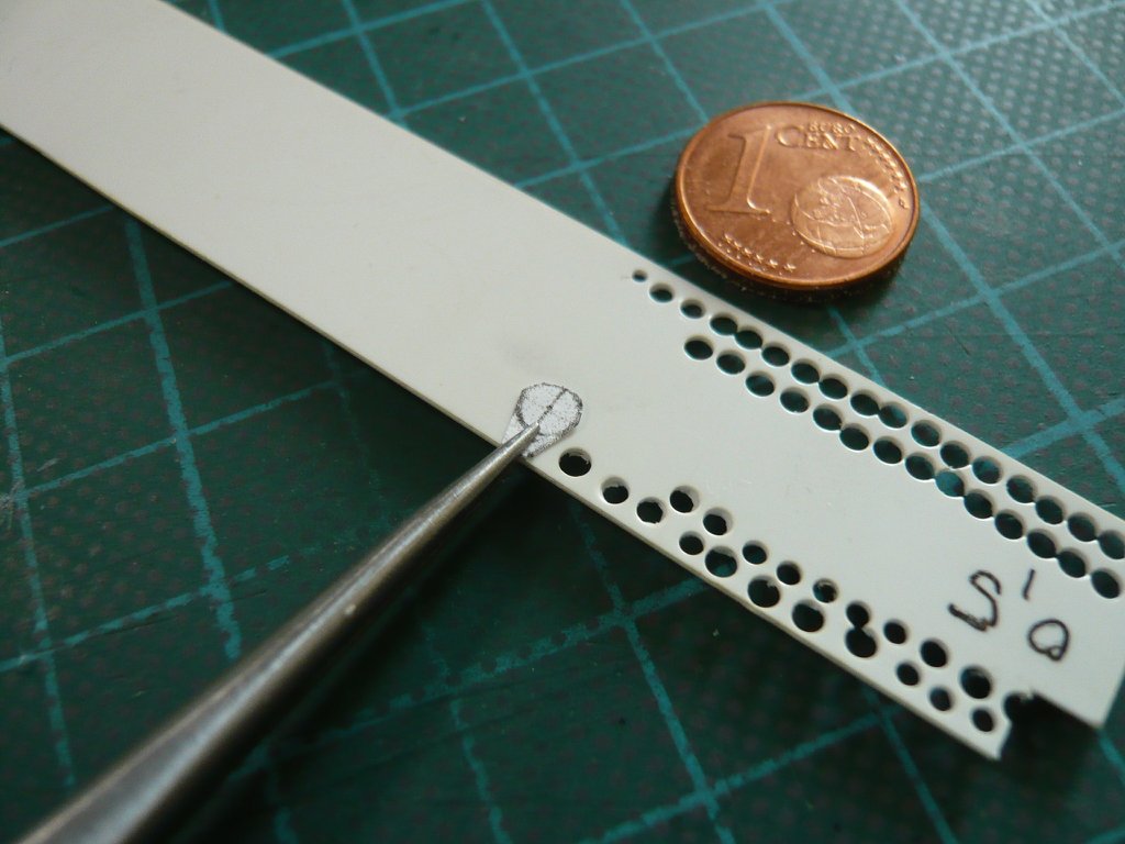 then it was punched out with the Chisel-cutter, 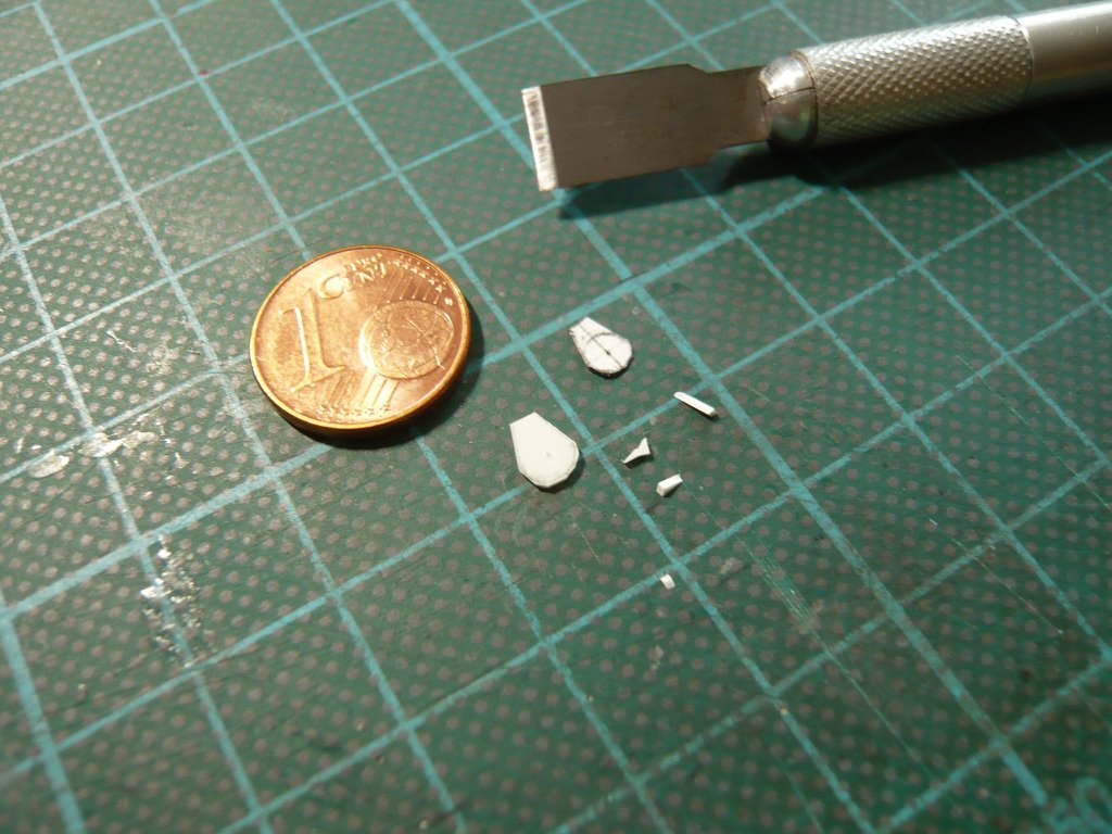 which then was sanded. 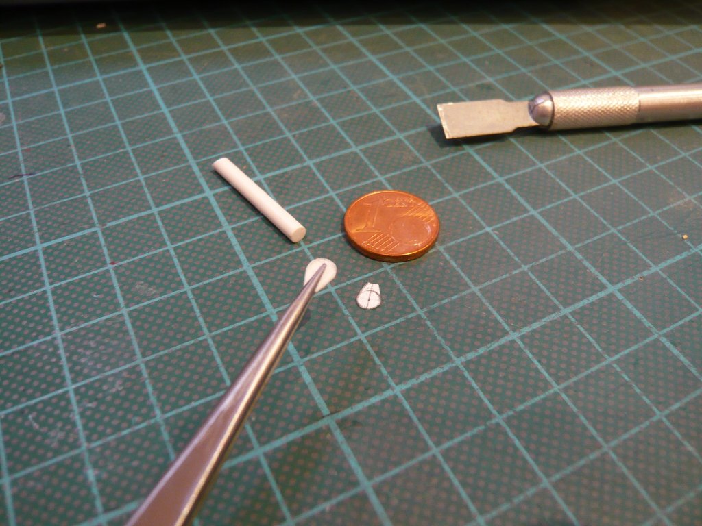 And this is how the test fitting looks on a Feedline dummy (Ø 3 mm). 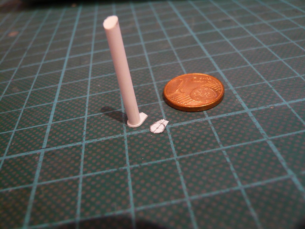 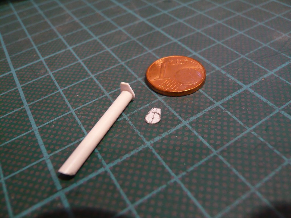 That's it then again, next follows the separation of the Feedline and the test fitting of the bow.
__________________
Greetings from Germany Manfred Under construction: Launch Pad 39A with Challenger STS-6 (1:144)
|
|
#2017
10-28-2019, 10:16 AM
|
||||
|
||||
|
Hello everybody,
the marking of the separation point on the LO2 Feedline was more difficult than expected due to the limited space conditions, but then I still succeeded. And then I bravely took the saw, and the job was done. These are the first images after the separation of the Feedline with the realization that the short bow was much harder to handle for testing, which is why I had to think of a new solution.  And so I came back to my Transparency stencil, which was made for it and only had to be slightly shortened. This allowed the bow with the stump above the Umbilical plate to be inserted into the large opening of the template and kept relatively stable.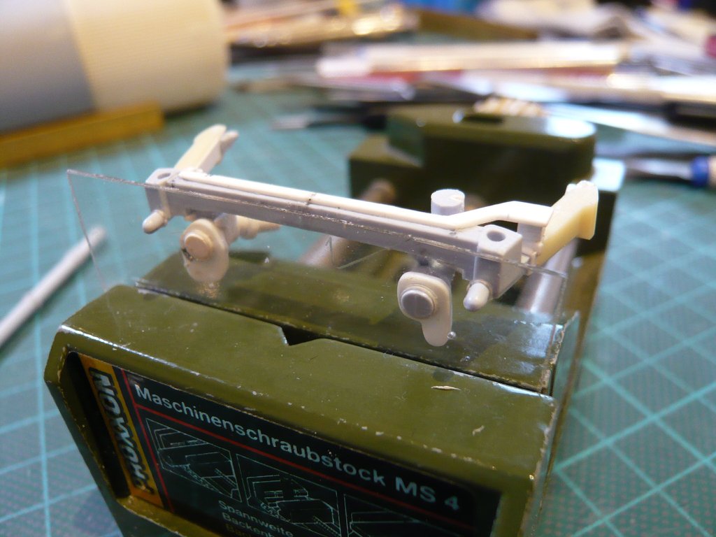 And by clamping the template in my Mini vise, the bow was easy to see from all sides.  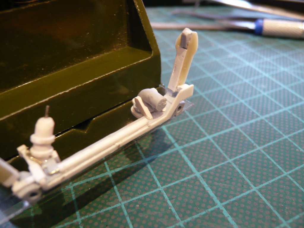 I was pleasantly surprised at how well the front of the bow did fit under the Cable Tray, 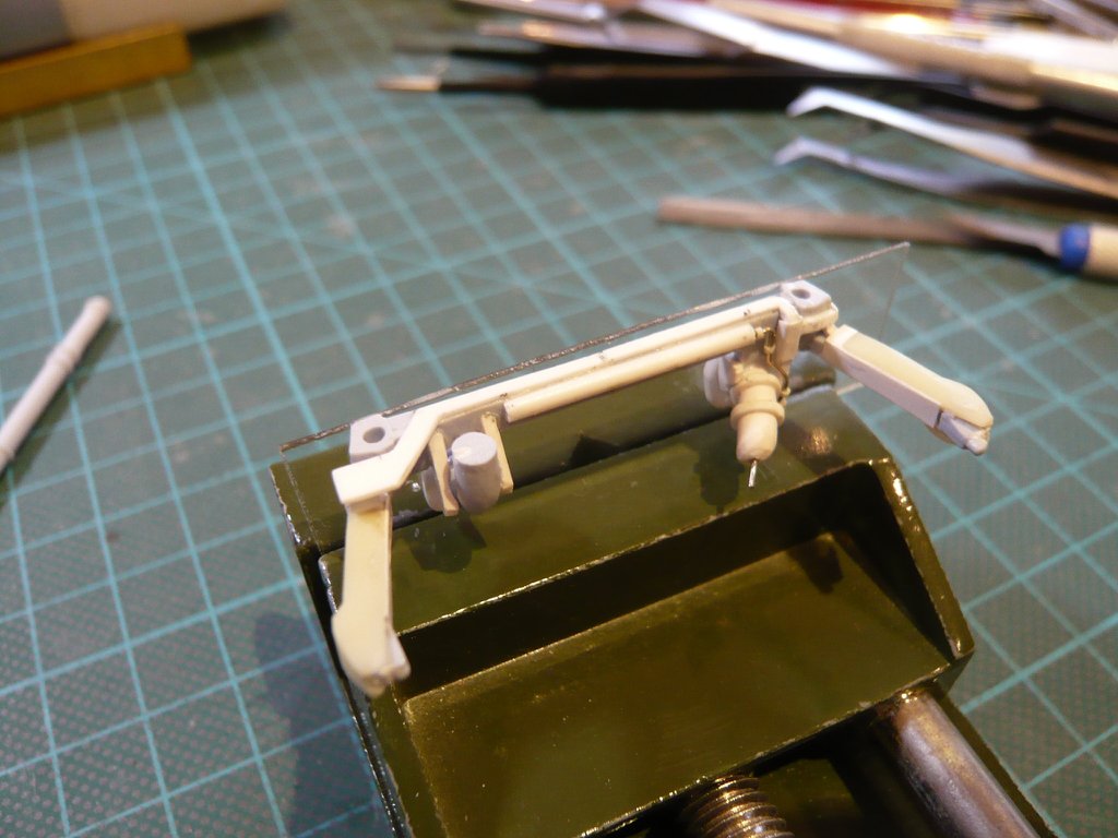 which was visible by placing the paper template. 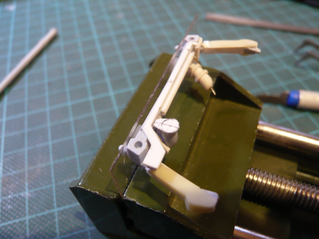 But after putting on the 0,5 mm Styrene support plate, the disillusionment came immediately,  because I had not thougt of it that the Cable Tray is also 0,5 mm thick, and the support plate with this then would be flush, but this is not correct because it must sit a little lower. because I had not thougt of it that the Cable Tray is also 0,5 mm thick, and the support plate with this then would be flush, but this is not correct because it must sit a little lower. 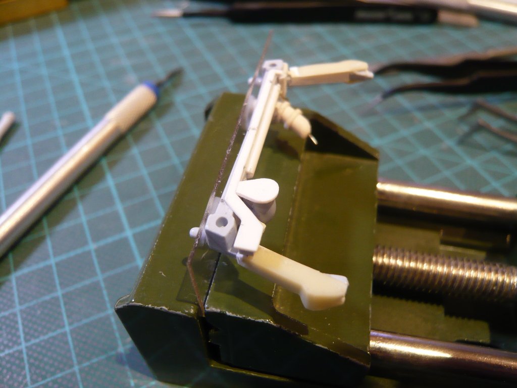 Consequently, either a thinner support plate ago, or the plate had to be ground down to about 0,3 mm, which I then have preferred. But more on that later.
__________________
Greetings from Germany Manfred Under construction: Launch Pad 39A with Challenger STS-6 (1:144)
|
|
#2018
10-28-2019, 05:36 PM
|
||||
|
||||
|
Hello everybody,
no sooner said than done! So I've sanded the Support plate between two nail files to a thickness of about 0,3 mm, and I have to say that I liked it better than before. 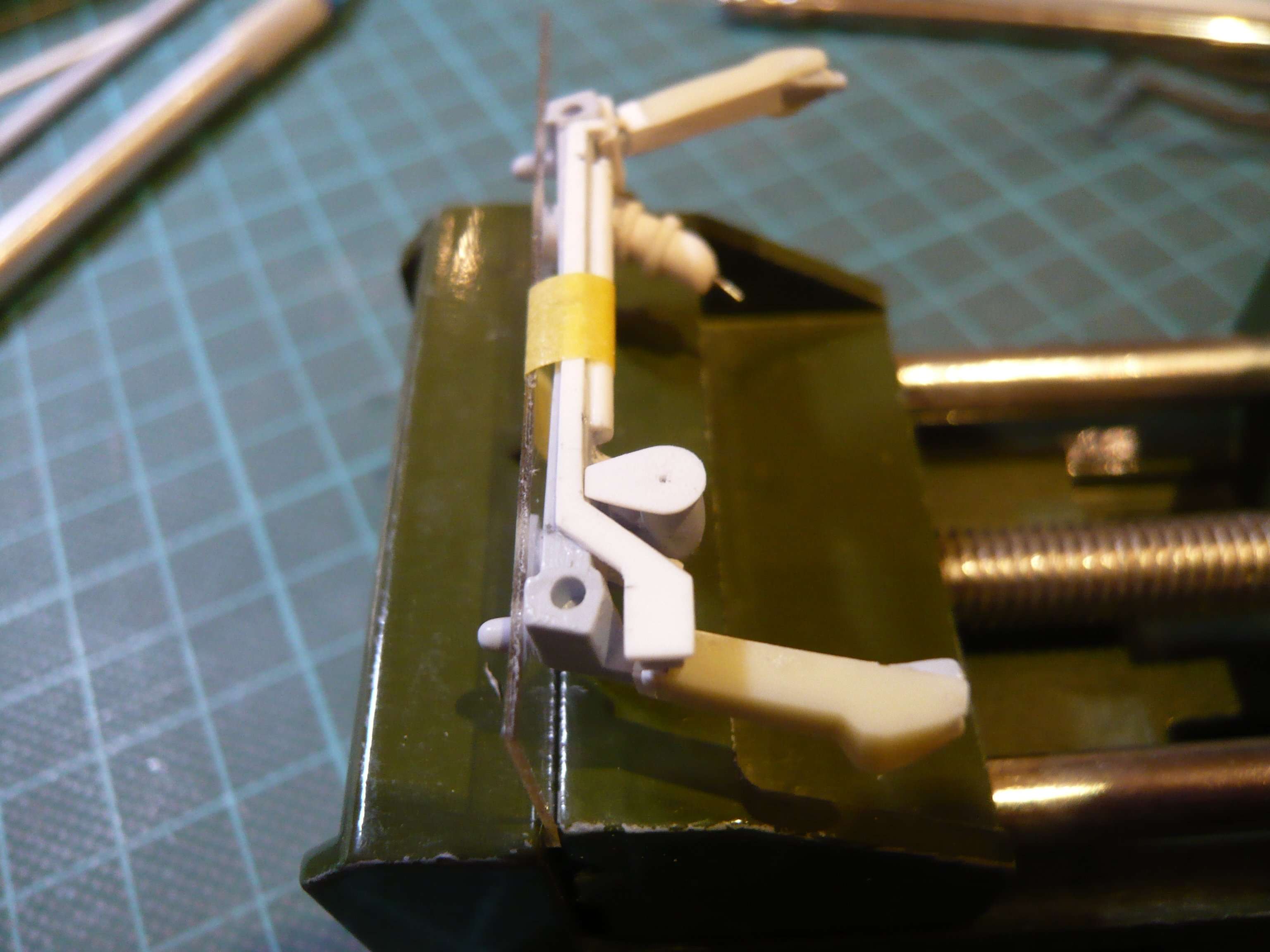 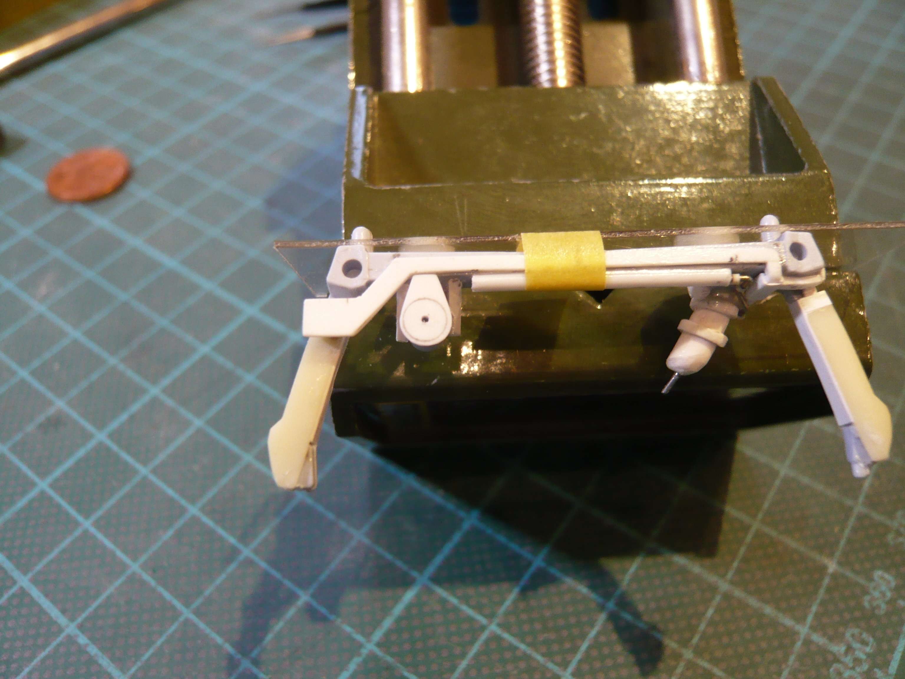 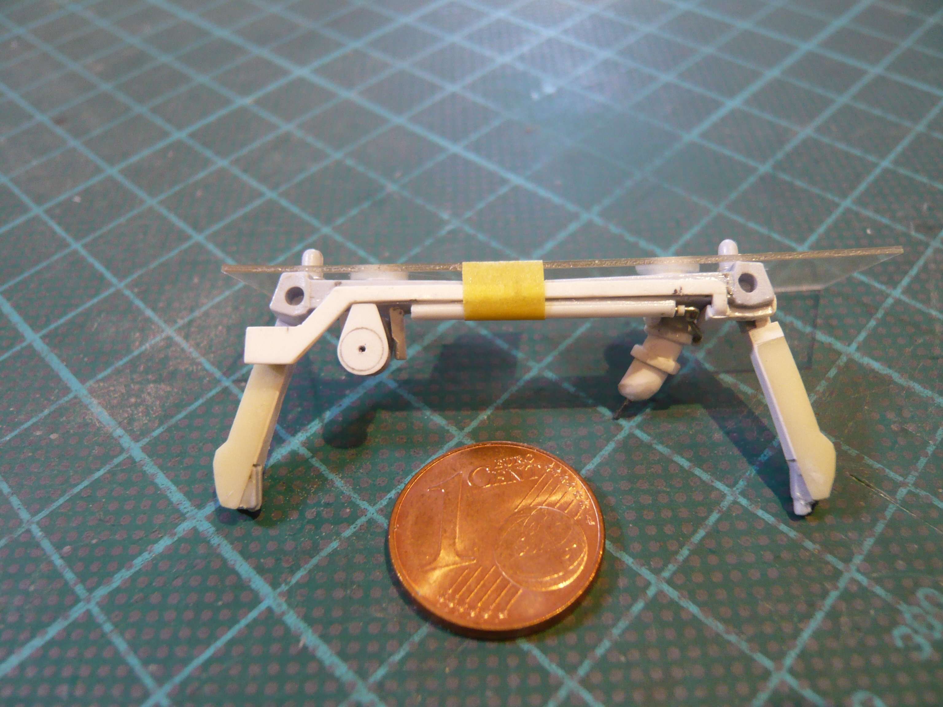 Now, the bow had to be glued as exactly as possible between the Support Brackets, but unfortunately I had to remove the stencil, which had previously fixed the position of the bow. 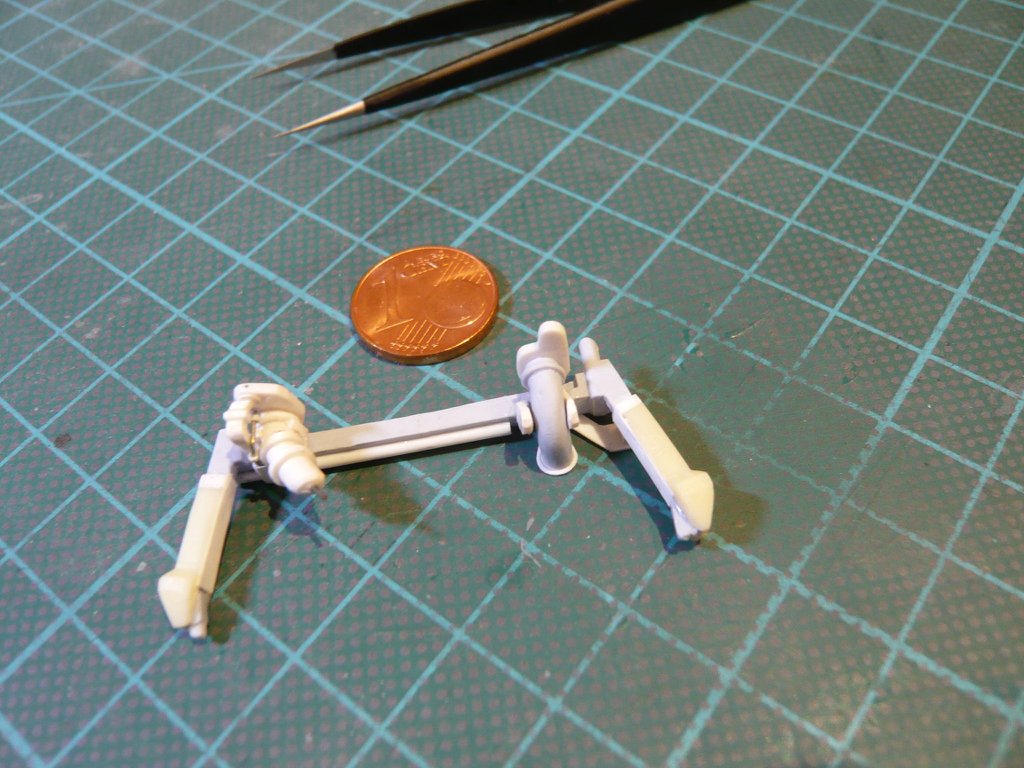 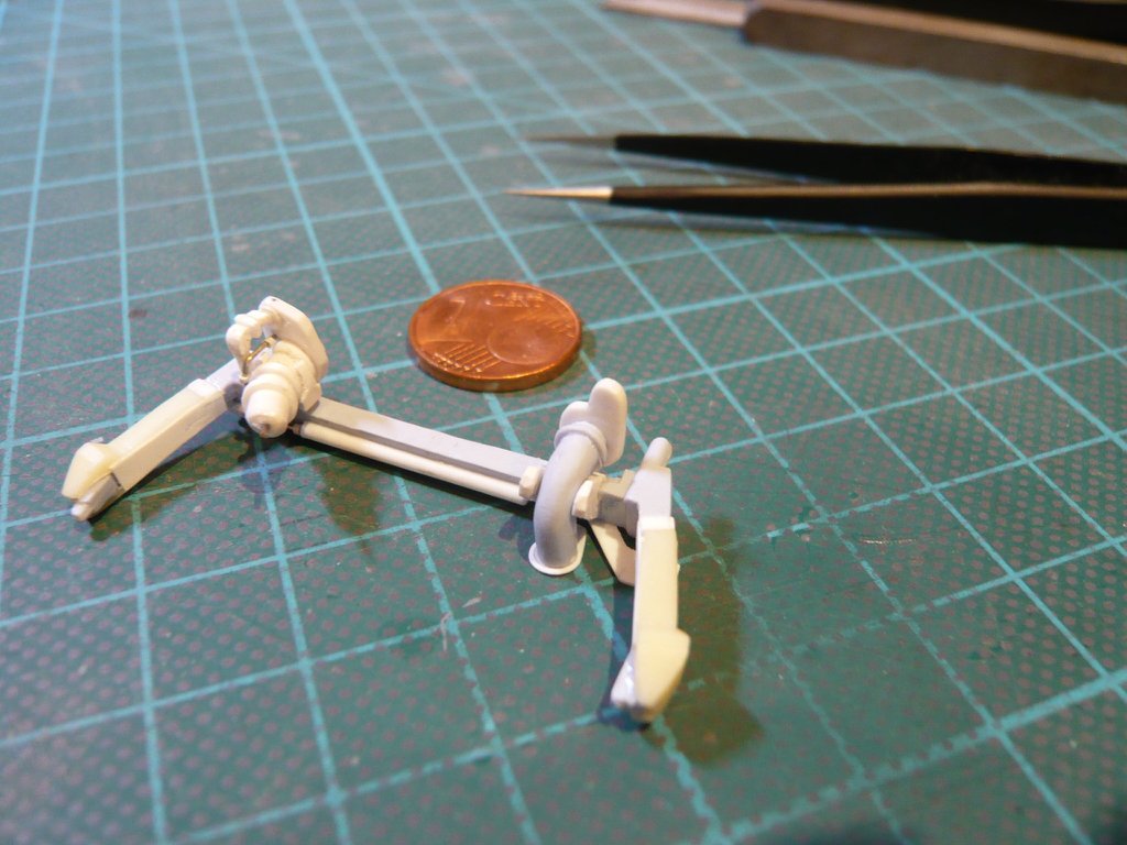 The crunchpoint here, however, is that the bow must be aligned with the Feedline, 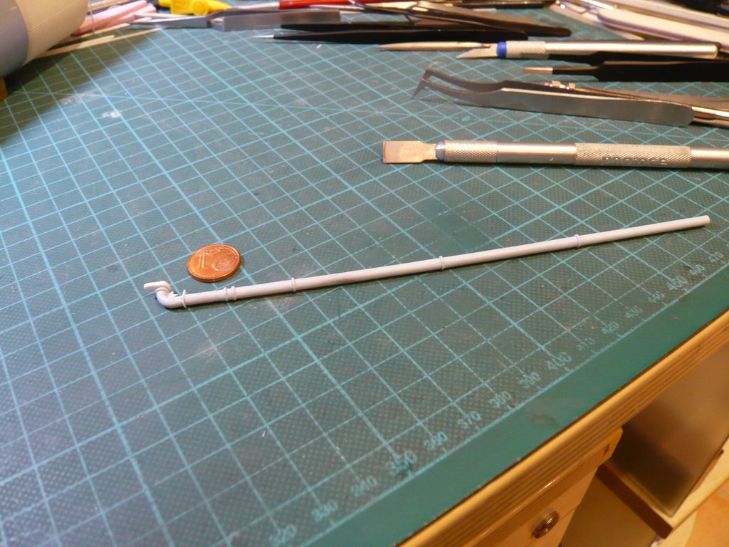 and the Umbilical Plate should lie flush against the opening of the Orbiter Door. 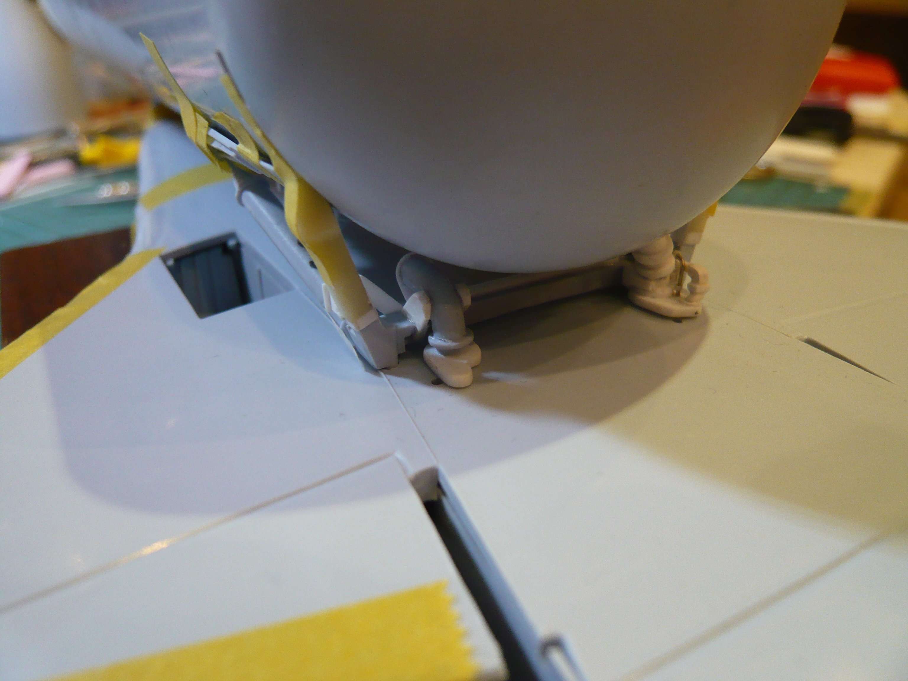 To accomplish this, I drilled the end of the Feedline in the middle and inserted a piece of Nickel silver wire as Centering aid. 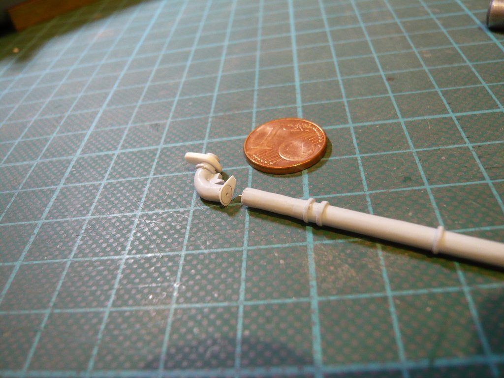  In this way I succeeded, first to glue the Support plate at the Crossbeam and then the Feedline-bow with the Support brackets, which will make the further work on the parts of the Cable Tray-TPS cladding much easier, since nothing can slip anymore. 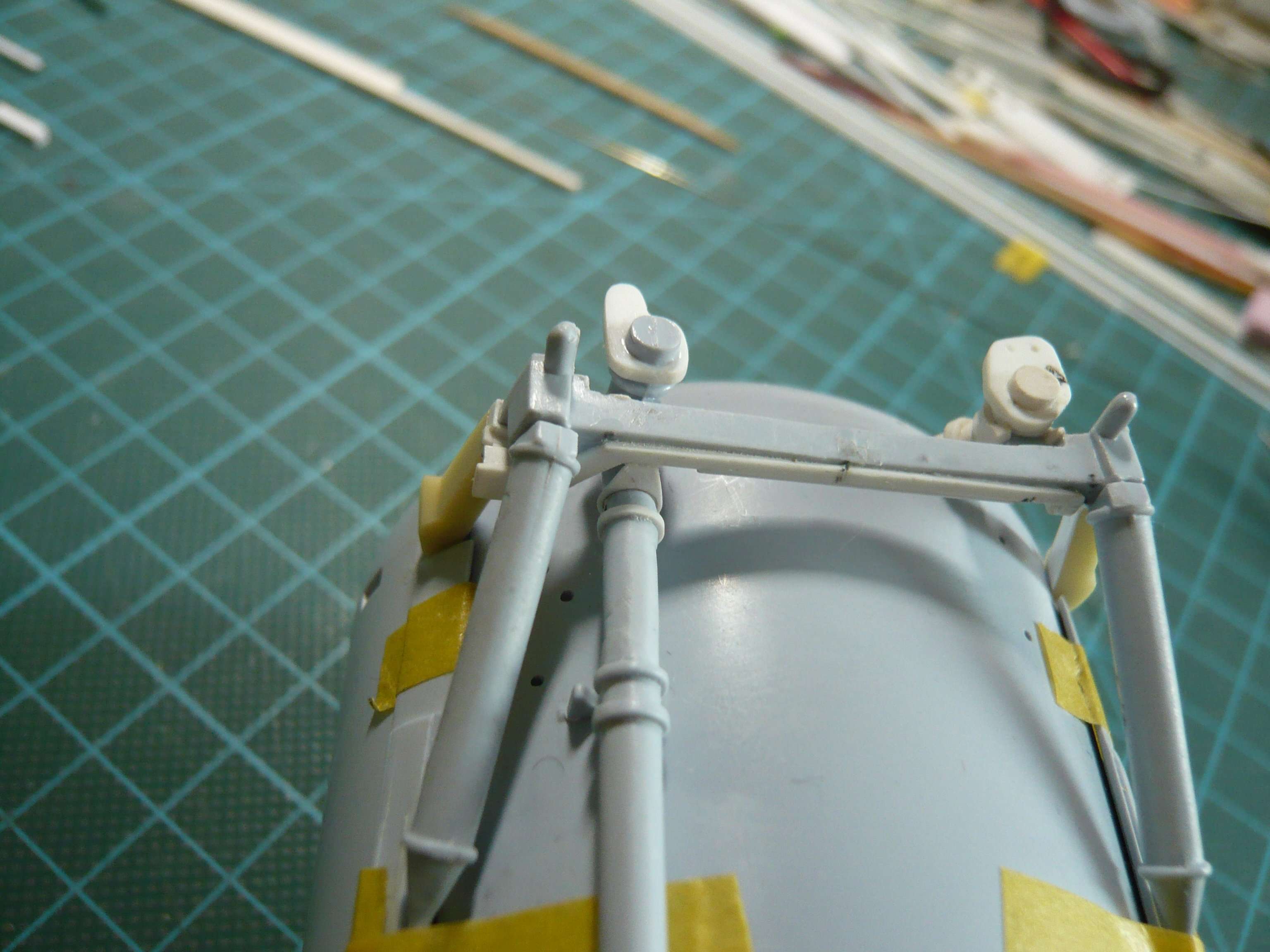 Then I've bent an Evergreen Strip (0,4 mm x 0,5 mm) under hot air around a rod (Ø 3 mm) and glued one ring of it in front of the Support plate. 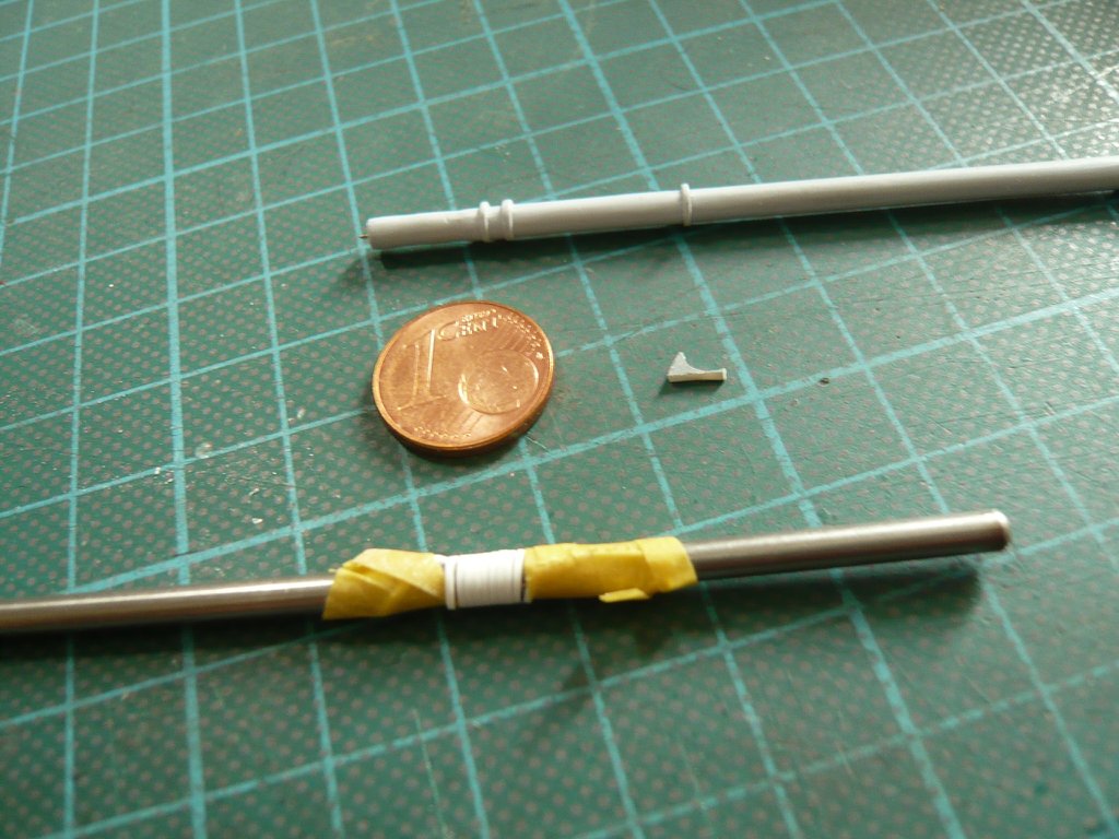 Then I've scratched the so called Pivoting Support missing at Airfix and glued it just behind the Intertank. 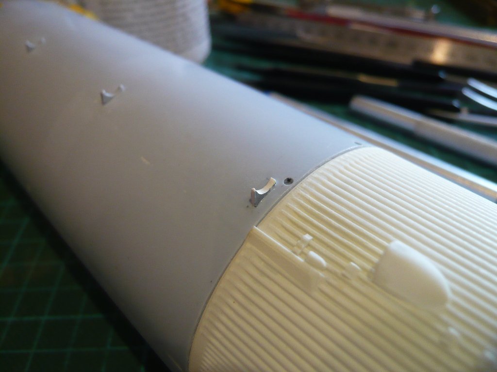 But this is only one half of the Feedline Support, as one can see in this image, as there is still a clamping ring over it, 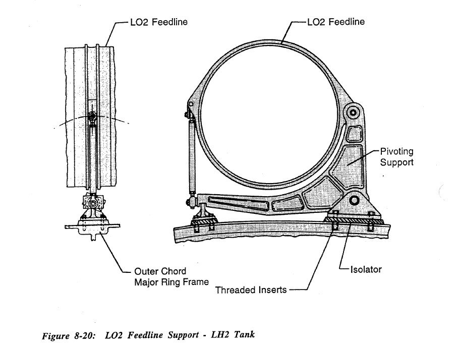 Source: System Definition Handbook SLWT, Vol. I (Lockheed Martin) which should be much narrower than at Airfix existing ring, as the comparison with the original photo shows, so I would have to modify these rings also a bit.   Source: forum.nasaspaceflight.com (Jester) Then there are also missing the wider Rings in front of the supports, which I'll scratch too. So all in all a lot of odds and ends, which is still waiting for me.
__________________
Greetings from Germany Manfred Under construction: Launch Pad 39A with Challenger STS-6 (1:144)
|
|
#2019
10-30-2019, 01:18 AM
|
||||
|
||||
|
Hello everybody,
and now to the LO2 Cable Tray along with the TPS Segments at the transition to the LO2 Umbilical Plate. As always, before the Scratch-building of assemblies and parts there is nothing like a thorough inventory and accurate detailed analysis.  ... ...  ... ... The beginning is again this photo for a better orientation, which helped me because of the direct side view already in the sizing of the Distribution box, on which I have marked the first three parts of this LO2 Umbilical assembly. Directly behind the distribution box is with the Part 1 a trapezoidal support part whose dimensions (length L, and upper and lower width) I've determined by reference to the diameter of the LO2 Feedline (Ø 3 mm).  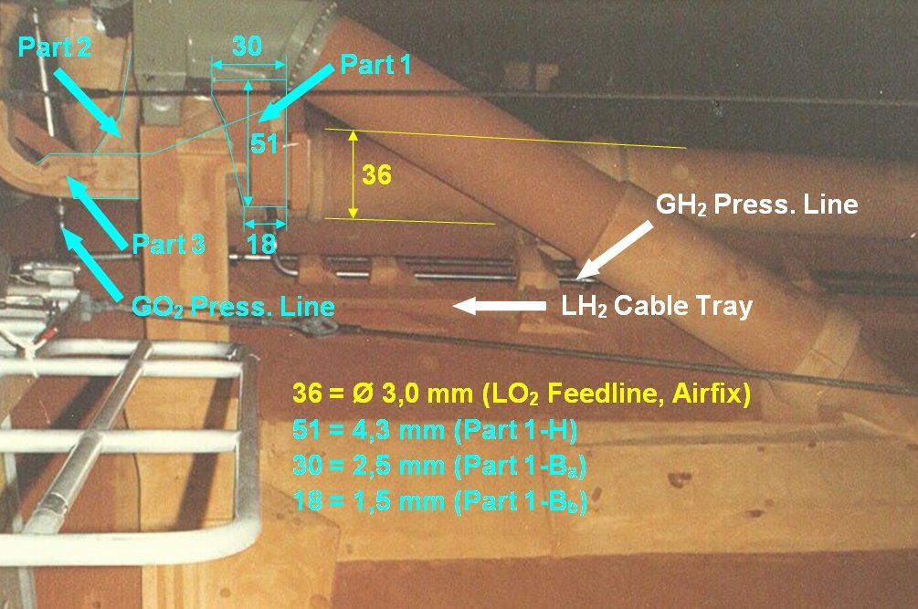 Source: georgesrockets.com (George Gassaway) On this rotated photo, one can see this here gray part a bit closer, whereby the linked original zoom is unfortunately rotated.  Source: forum.nasaspaceflight.com (DaveS) Therefore, here's still a section in original resolution, on which one can see that this part is directly connected with the Distribution box and with the LH2 Cable Tray.  And directly behind the oblique branch (Part 3) runs from the Cable Tray, which is connected with the Part 2 and passes over the Parts 4/5 to the Umbilical plate. 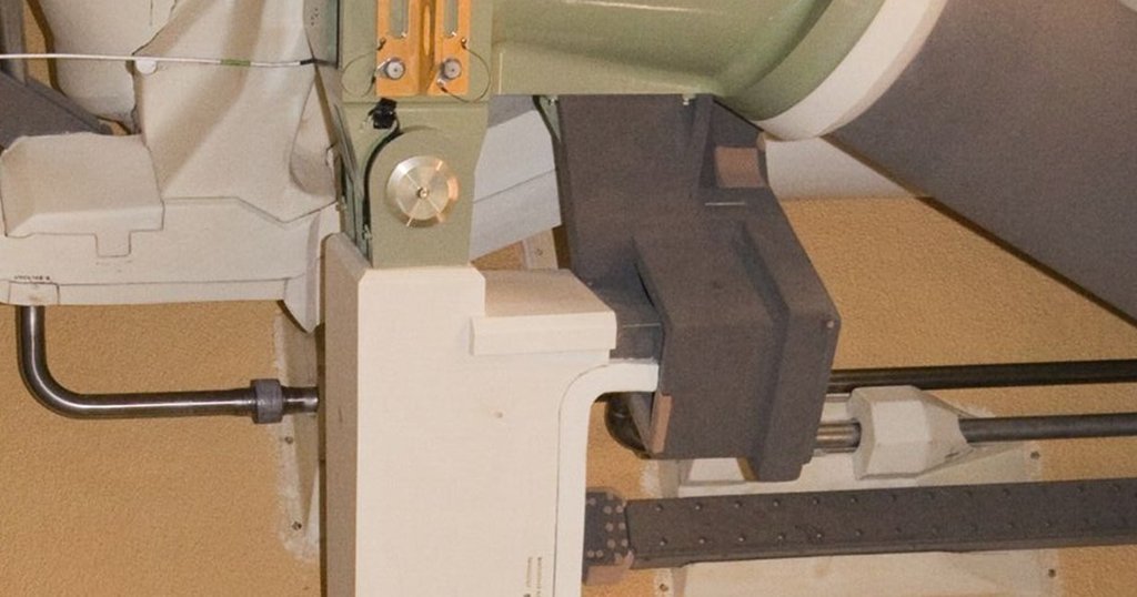 Thus, only the width of the part is missing, which I have determined from this photo, which allows me to scratch the Part 1. 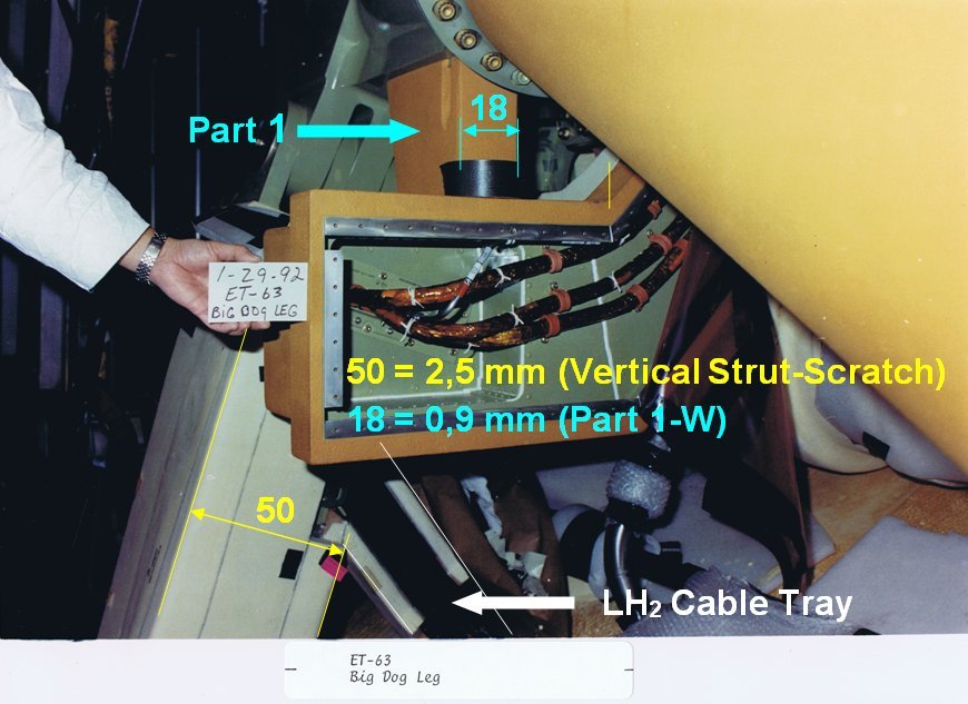 In this picture one can see the cables coming out of the vertical strut, of which one part, as just described, runs up to the LO2 Umbilical plate and the remainder to the LH2 Umbilical plate. In this rear view, the Parts 3-5 are admittedly covered by cuffs, but one can nicely see the entrance of the LH2 Cable Tray into the Vertical Strut. 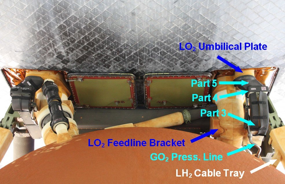 And in this order, I will now try to scratch these five parts step by step.
__________________
Greetings from Germany Manfred Under construction: Launch Pad 39A with Challenger STS-6 (1:144)
|
|
#2020
10-30-2019, 09:55 AM
|
||||
|
||||
|
I keep learning new techniques in this thread, and it's very informative on the actual subject as well. Keep it up!
__________________
"The world is big" On hold: Fuyuzuki, Zao, Zara, Akizuki, Past works: XP55 Ascender, CA Ibuki, Seafang F32, IS-3, Spitfire V, J-20
|
 |
|
|


 Linear Mode

