


|
|
|
#2071
 03-21-2020, 04:38 PM
|
||||
|
||||
|
Hello everybody,
today quickly to the Closeouts, which I transferred from the PE board to an Evergreen Styrene Sheet (0,2 mm) because it makes it easier to transfer the contour to the ET.  The part should not be glued for the time being, but only after the SOFI Pattern-Tape-Spiral has been glued on, i.e. immediately before the Flour coating. The part should not be glued for the time being, but only after the SOFI Pattern-Tape-Spiral has been glued on, i.e. immediately before the Flour coating.  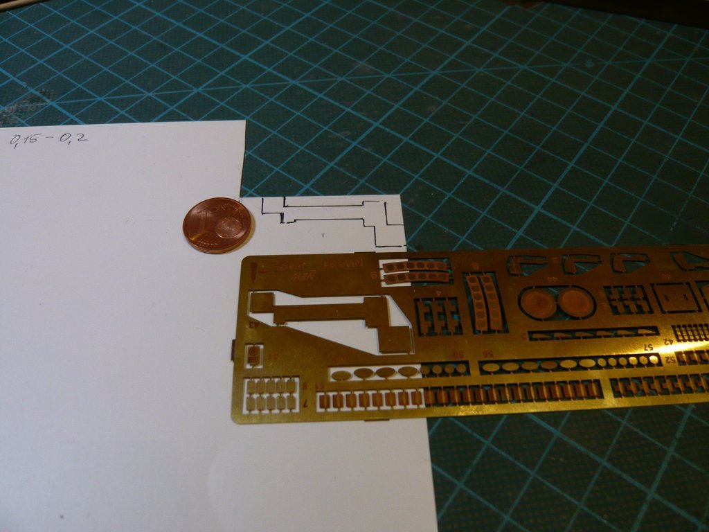 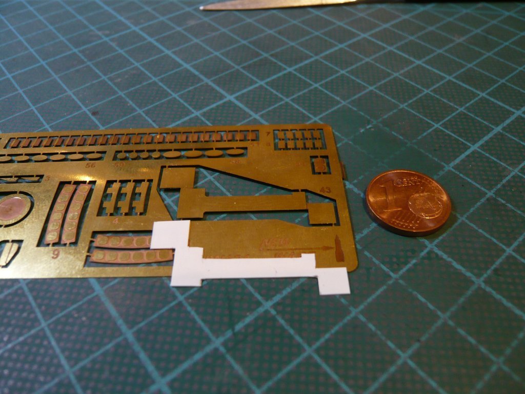 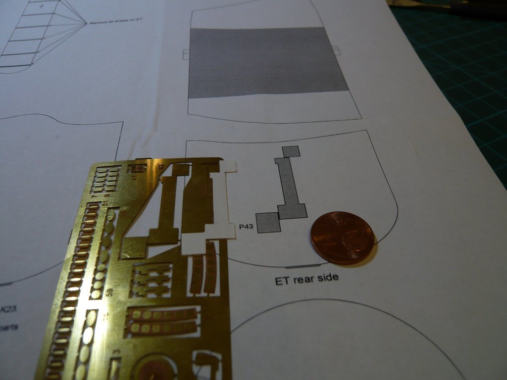 After I had determined the exact position of the Closeouts on the ET, 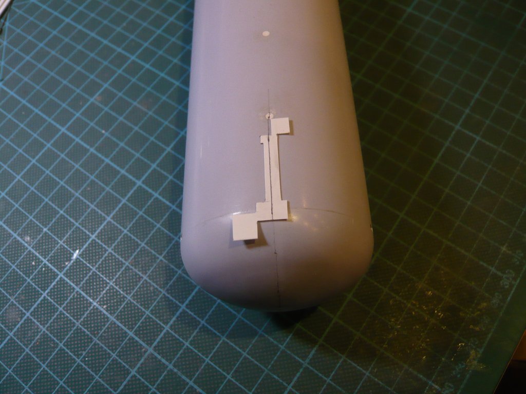 I've fixed it with masking tape (2 mm) and was able to trace the contour.  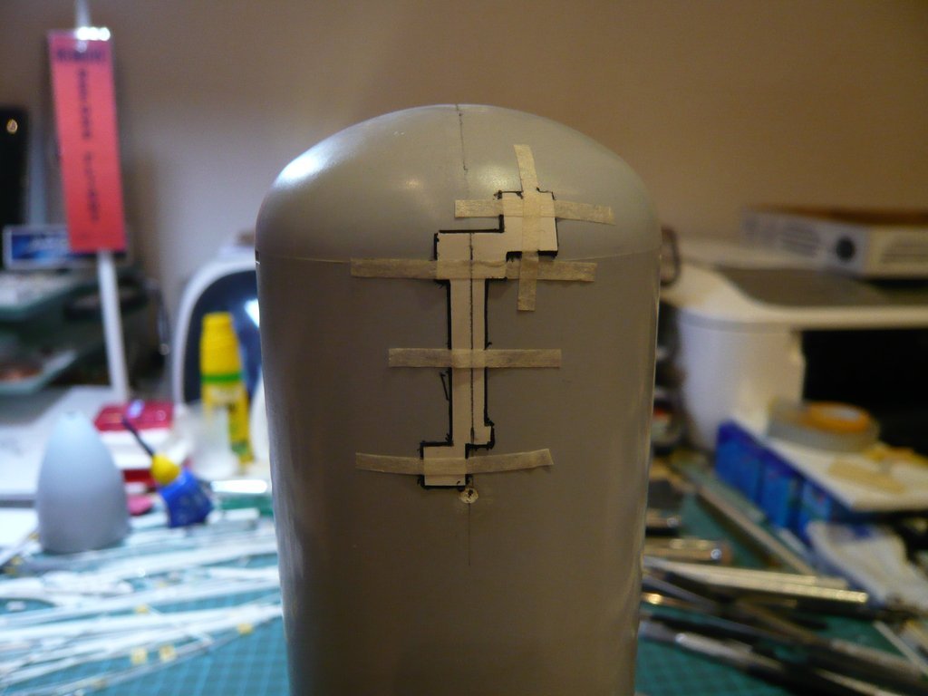 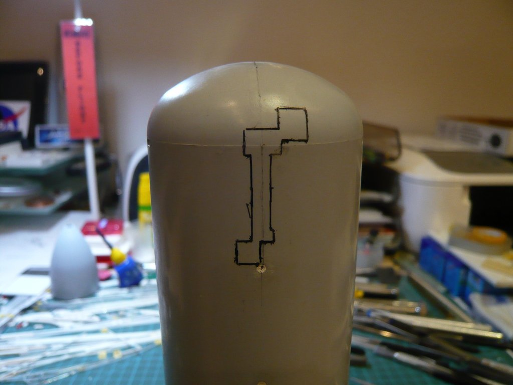 Now I can start soon with gluing on the Tape spiral and then to cut out the contour so that I can subsequently glue on the Closeouts. And with the two Longerons I will do it same way.  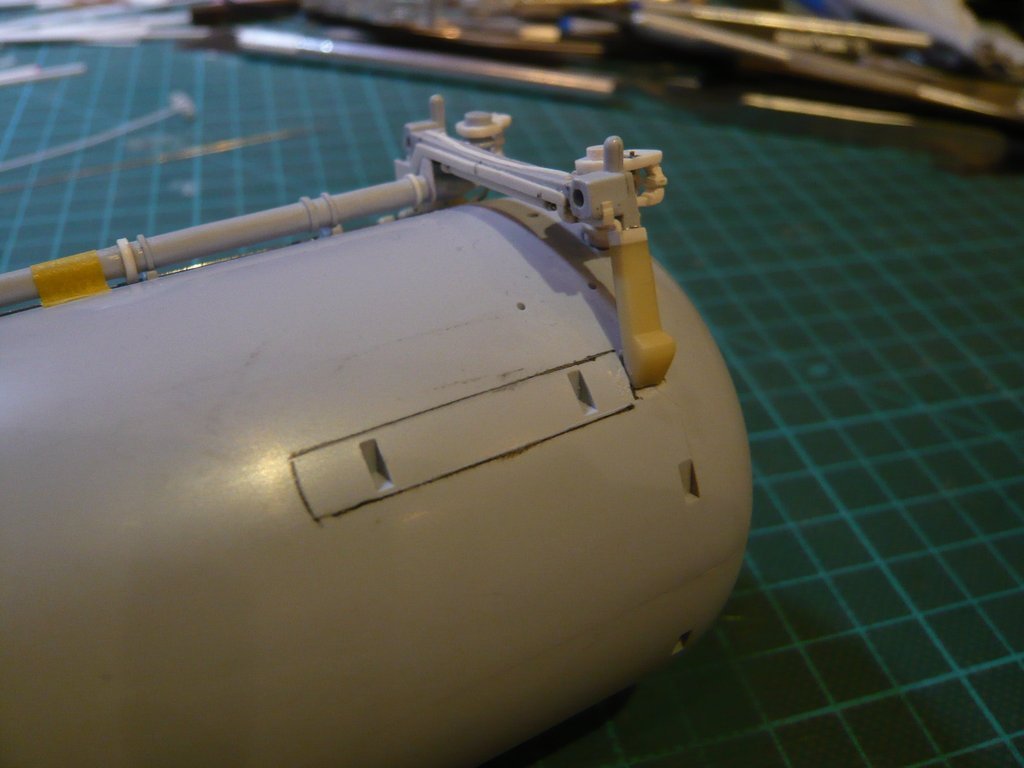 With that I would like to leave it for now.  
__________________
Greetings from Germany Manfred Under construction: Launch Pad 39A with Challenger STS-6 (1:144) 
|
|
#2072
03-22-2020, 02:09 AM
|
||||
|
||||
|
Hello everybody,
today I want to present you a small update, regarding some small details at the Thrust struts and Longerons, which I still would like to modify because the original items look a bit different than in the Airfix Kit.  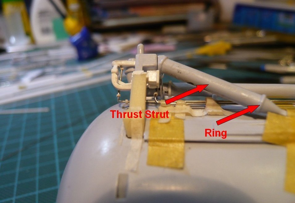 As one can see in this image of the ET-6, the diameter of the Thrust strut in the front part is a little bit larger and the front ring a little wider. 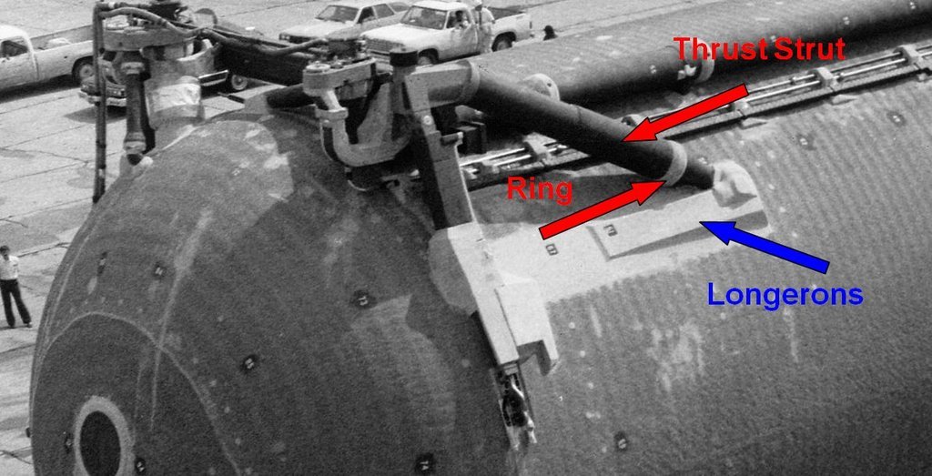 Source: forum.nasaspaceflight.com (Jester) But at the ET there are still a few little things like these Thrust Struts and Longerons, which I still would like to modify because in the original they look a little different than in the Airfix Kit. As one can see in this image of the ET-6, the diameter of the oblique struts in the front half is slightly larger and the front ring is a little wider,  Source: forum.nasaspaceflight.com (Jester) which one can see more clearly in this image of the ET-33 (STS-36), from which I determined the dimensions for the sheath. 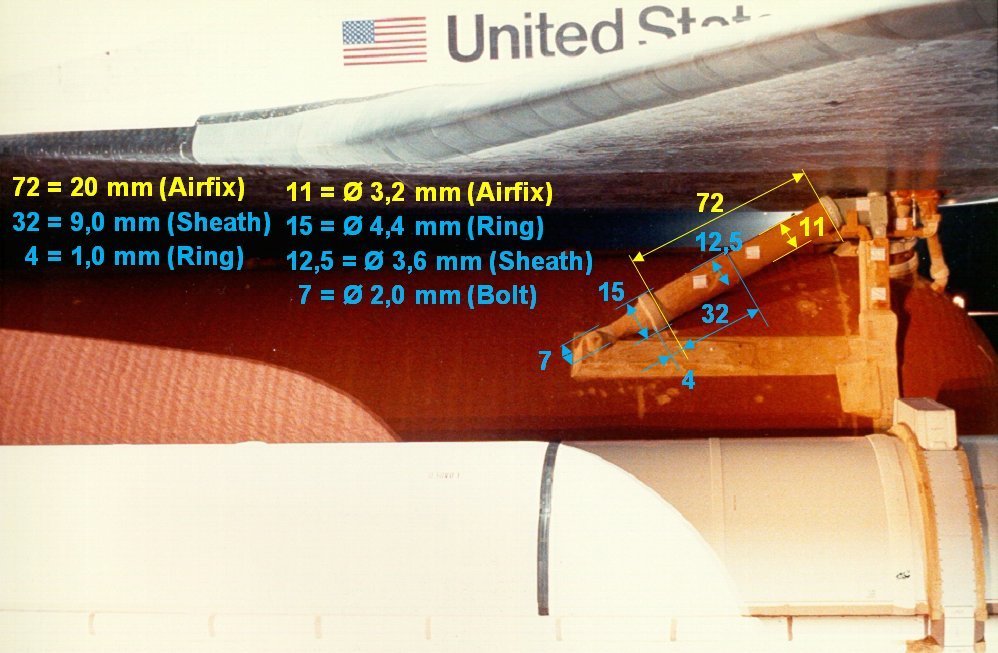 Source: georgesrockets.com (George Gassaway) As can be seen from this, the sheath in 1:144 should only have a wall thickness of 0,2 mm, which makes the selection of a suitable material somewhat difficult, since insulating hose, I like to use for such things, for inner diameters of approx. 3 mm but is too thick-walled and this time is eliminated. So I had to think about something else  and first had thought of adhesive film, as it can often be found in the supermarket as a price label. To do this, I cut a 9 mm wide strip and wrapped it around the strut a few times until it had a diameter of approx. 3,6 mm. and first had thought of adhesive film, as it can often be found in the supermarket as a price label. To do this, I cut a 9 mm wide strip and wrapped it around the strut a few times until it had a diameter of approx. 3,6 mm. 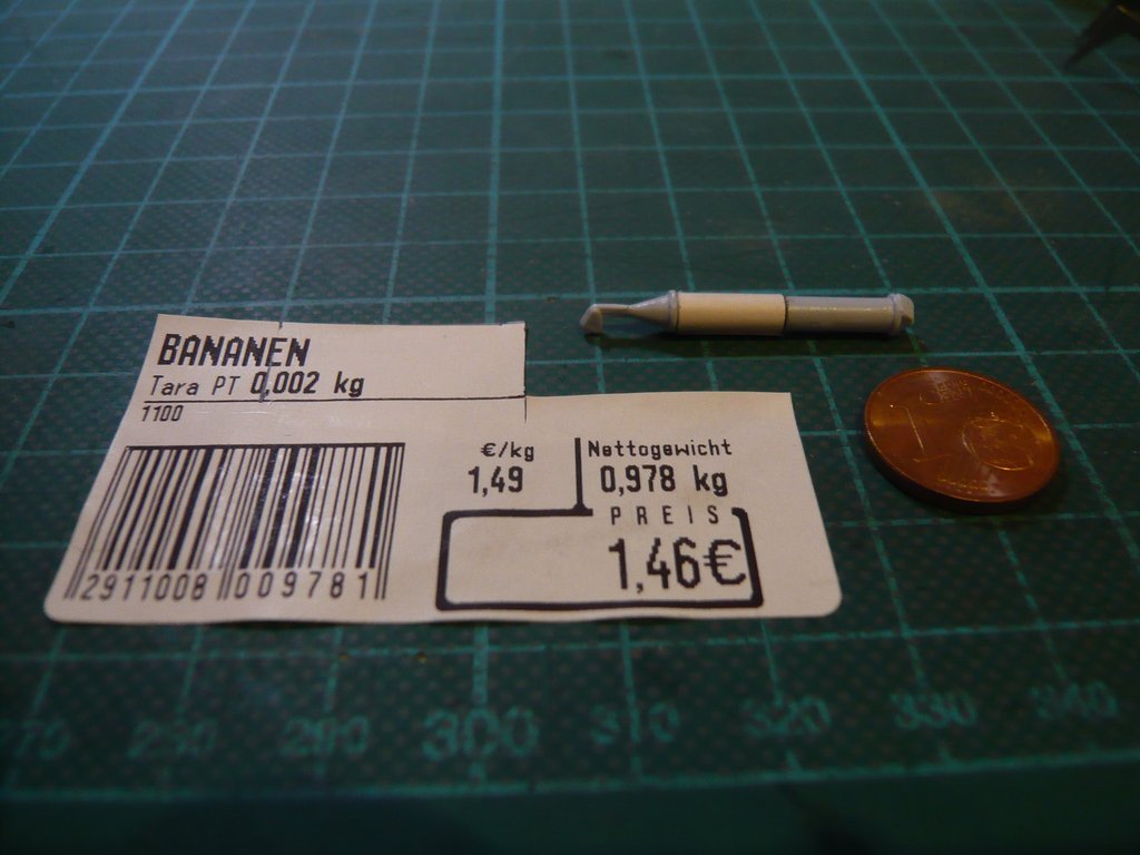 That would also work if necessary, but then one would have to accept the overlap at the end of the winding, which gradually opened again, which I didn't like.  Then I came up with the following idea,  and these were the well-known Drinking straws, some of which I had put aside a long time ago. Their diameter is indeed a bit too large at 5 mm, but the wall thickness of approx. 0,2 mm would fit to get the required Ø 3,6 mm. and these were the well-known Drinking straws, some of which I had put aside a long time ago. Their diameter is indeed a bit too large at 5 mm, but the wall thickness of approx. 0,2 mm would fit to get the required Ø 3,6 mm. 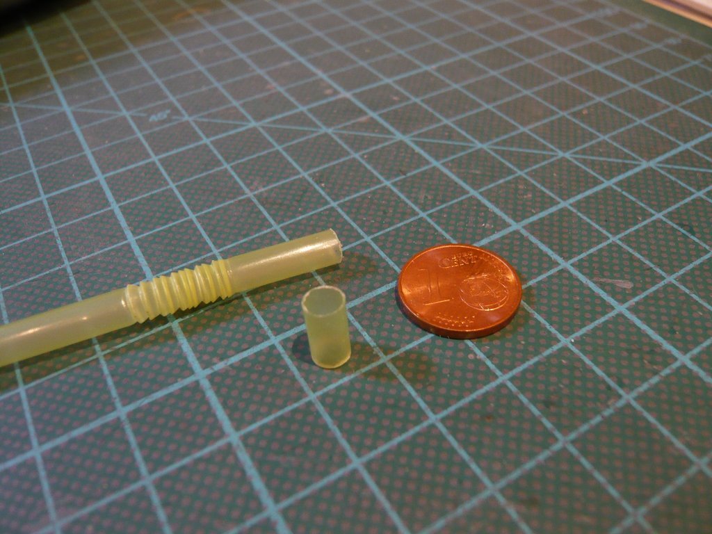 To do this, I've slit a 9 mm long sheath lengthways and then wound it as tightly as possible on a steel rod with a smaller diameter (Ø 2,5 mm) and fixed it with a clothespin, 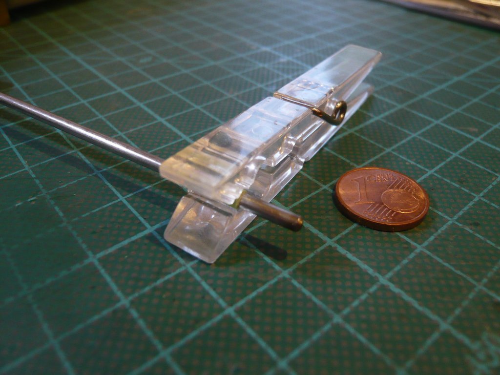 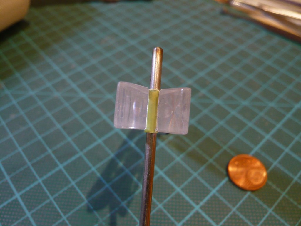 and then placed in a hot water bath for a few minutes for molding. 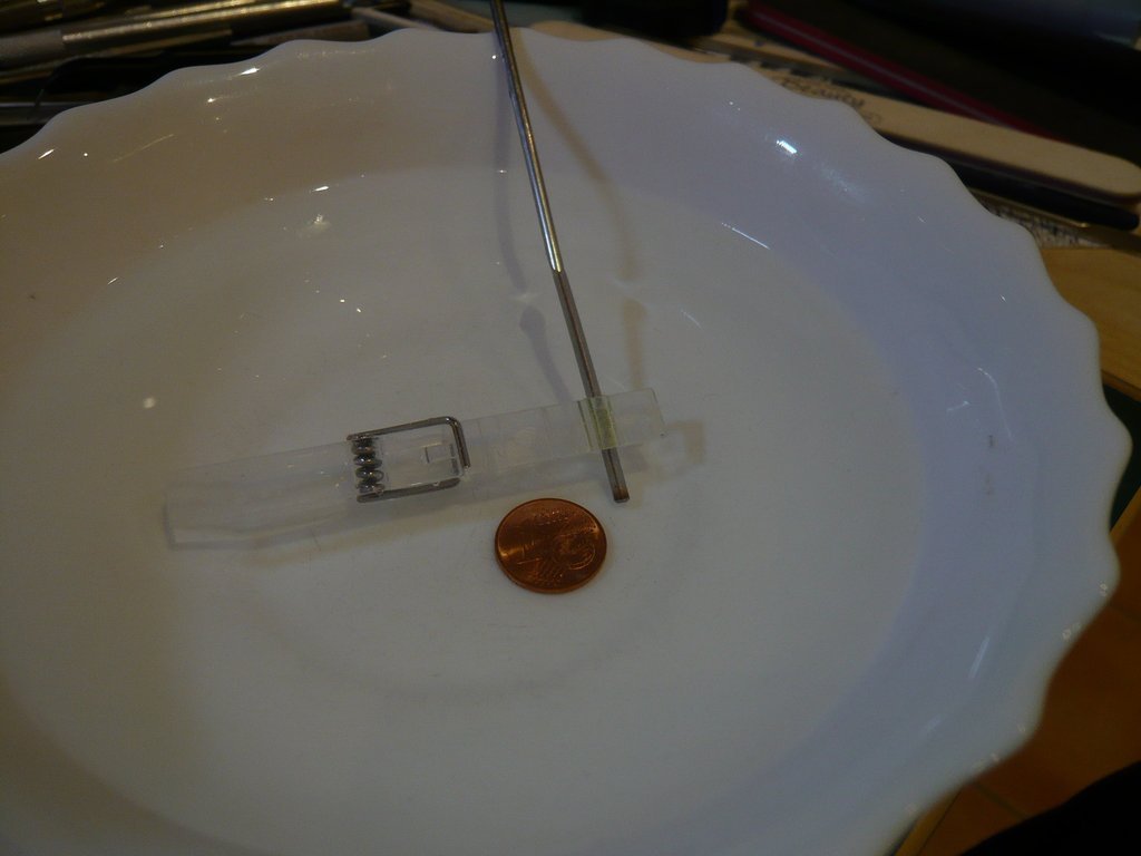
__________________
Greetings from Germany Manfred Under construction: Launch Pad 39A with Challenger STS-6 (1:144)
|
|
#2073
03-22-2020, 02:11 AM
|
||||
|
||||
|
The circumference of the resulting wrapped sheath I've then shortened accordingly,
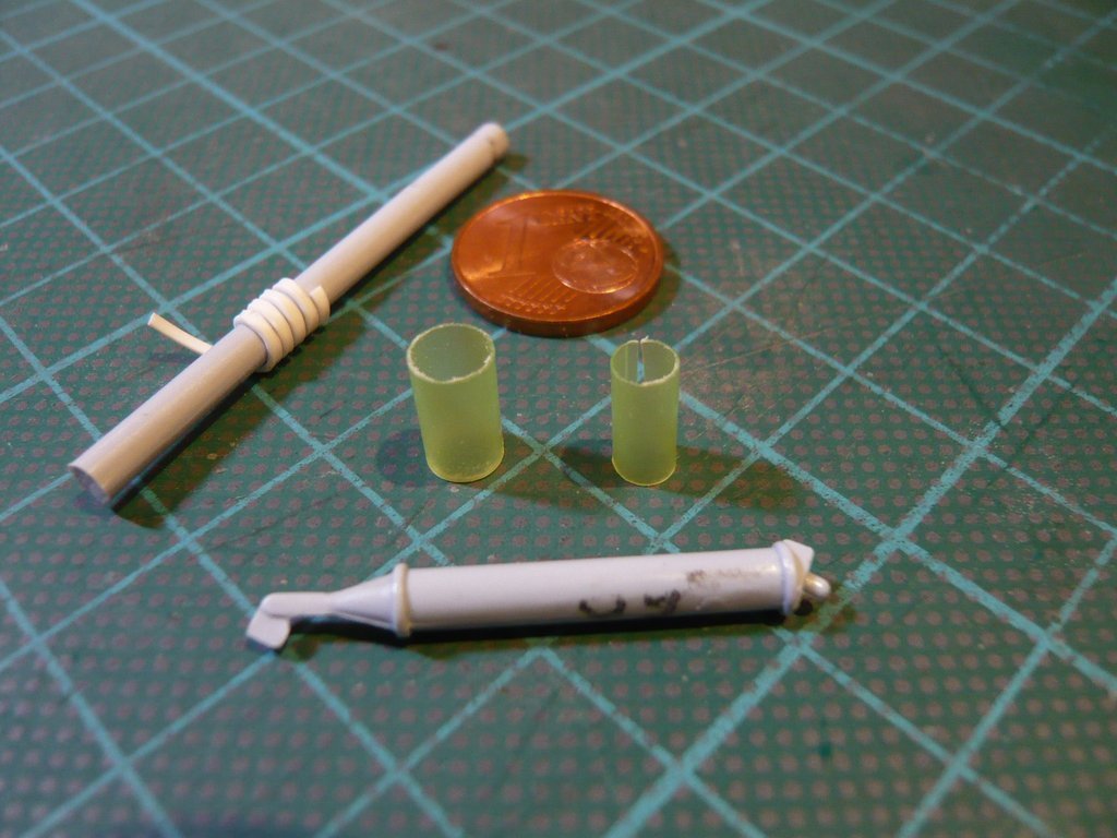 so that there was no overlap on the Airfix strut. By the way, on the left in the image one can already see the prepared spiral for the wider front rings (0,5 mm x 1 mm). 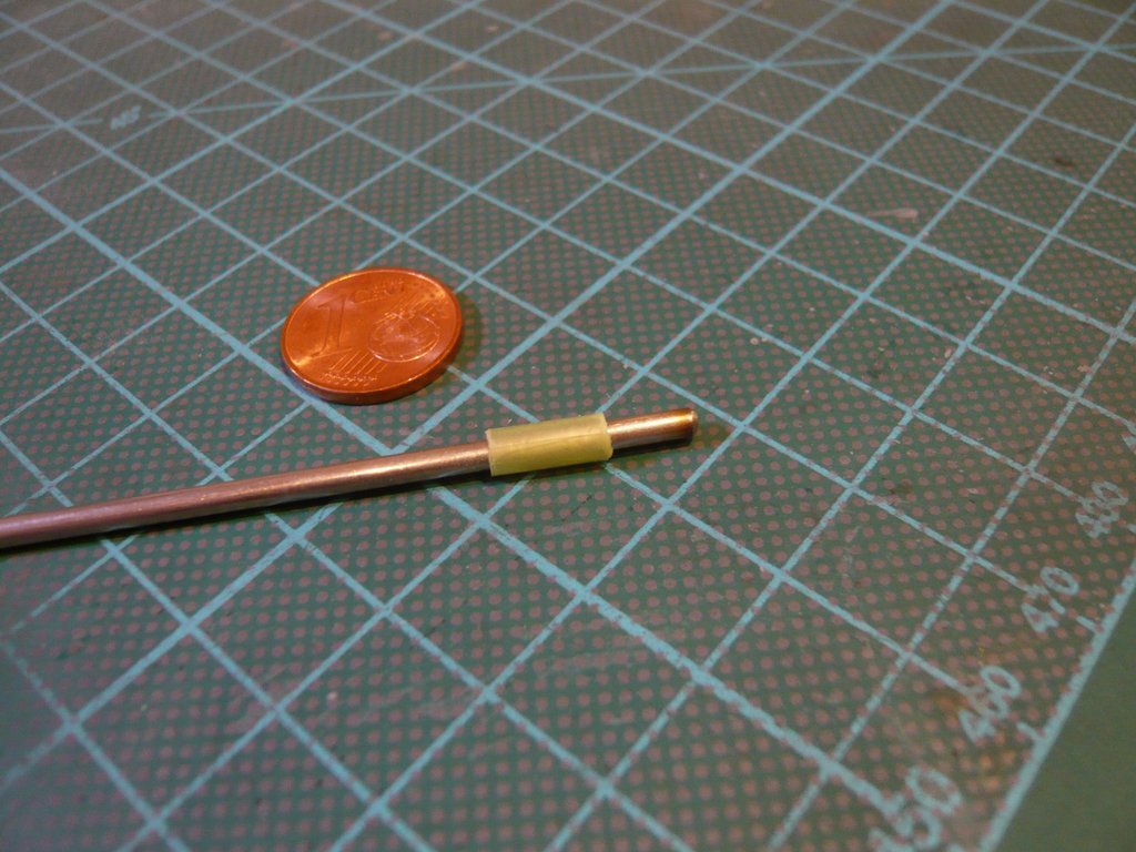 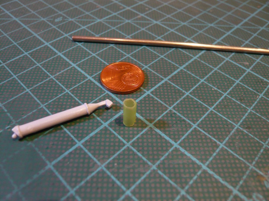 And as the test measurement showed, the required diameter of the sleeve was actually 3,6 mm. 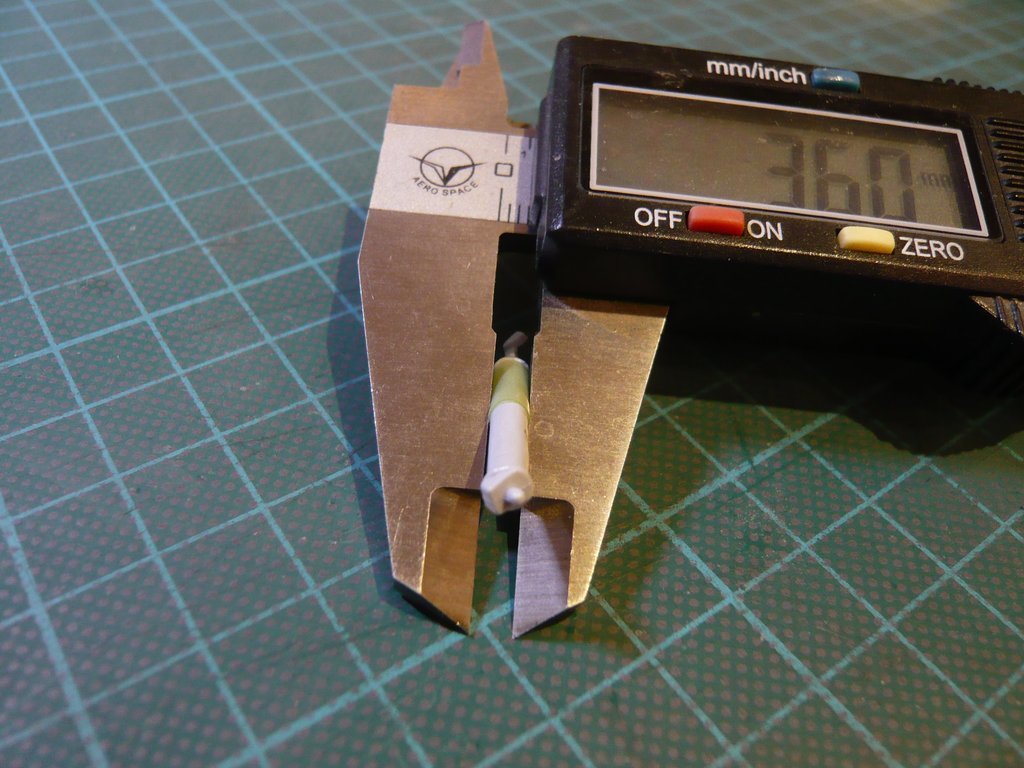 Here one can see a comparison of both variants, whereby I've chosen for the lower one. 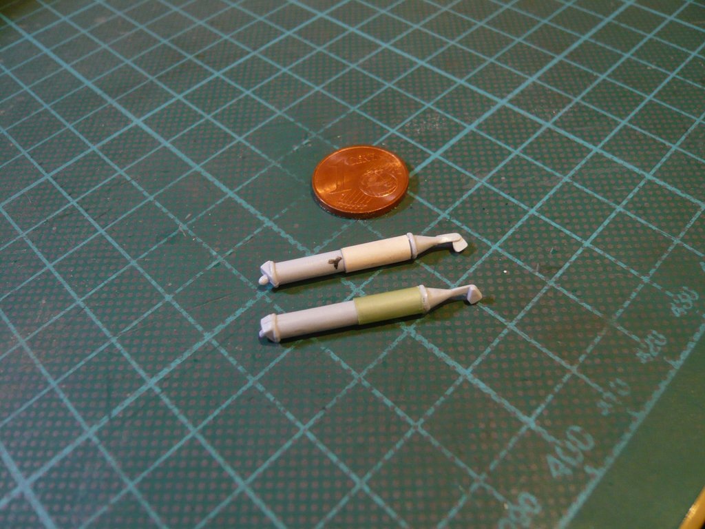 Before I could glue the sheaths onto the struts, I first had to remove the rings that were too narrow to be able to thread on the wider rings, 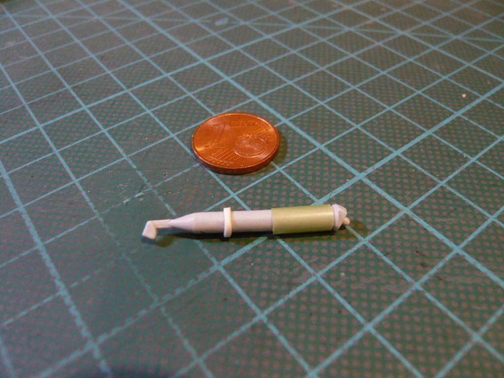 that are already glued here. 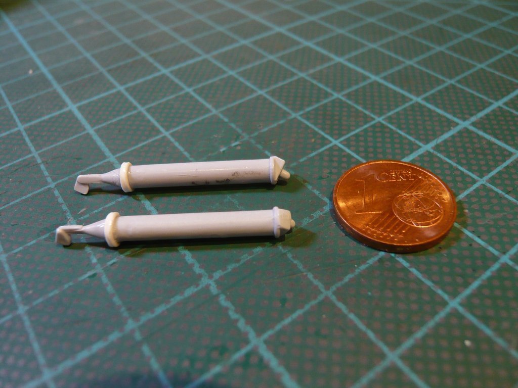 Then the sheaths could be pushed on and glued. 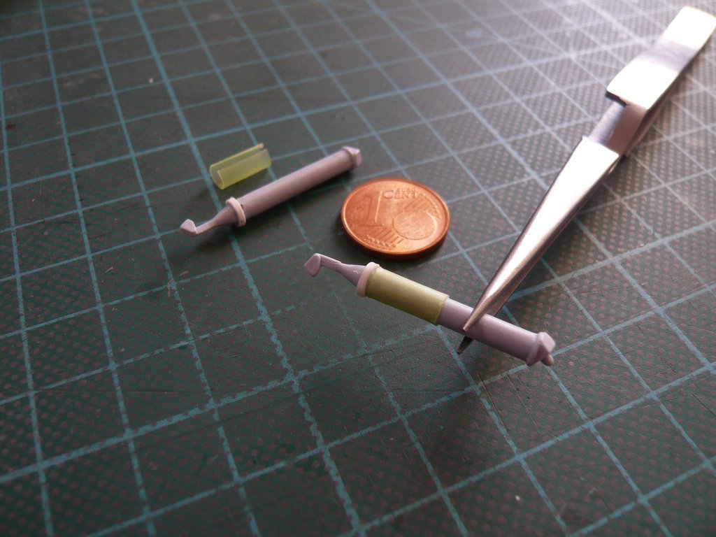 And now still for the modification of the Longerons, for what I've used again Apoxie Sculpt, of which both components had to be mixed in a 1:1 ratio by kneading, 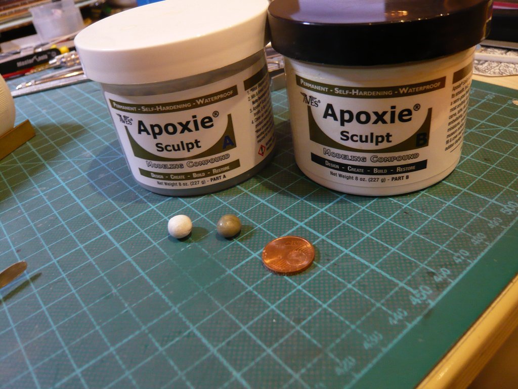 until a bright color appeared. With that it was then possible to fill in and model the middle areas between the slants, 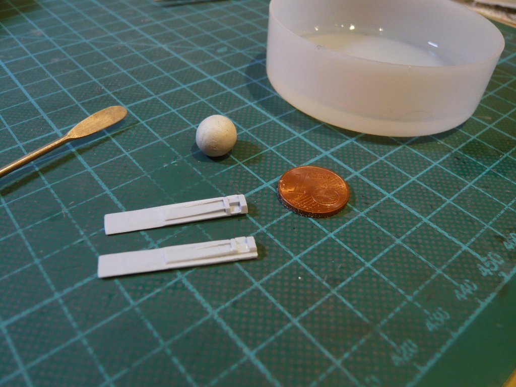 in order to match them to the shape of the real Longerons. In this condition I've let everything dry, 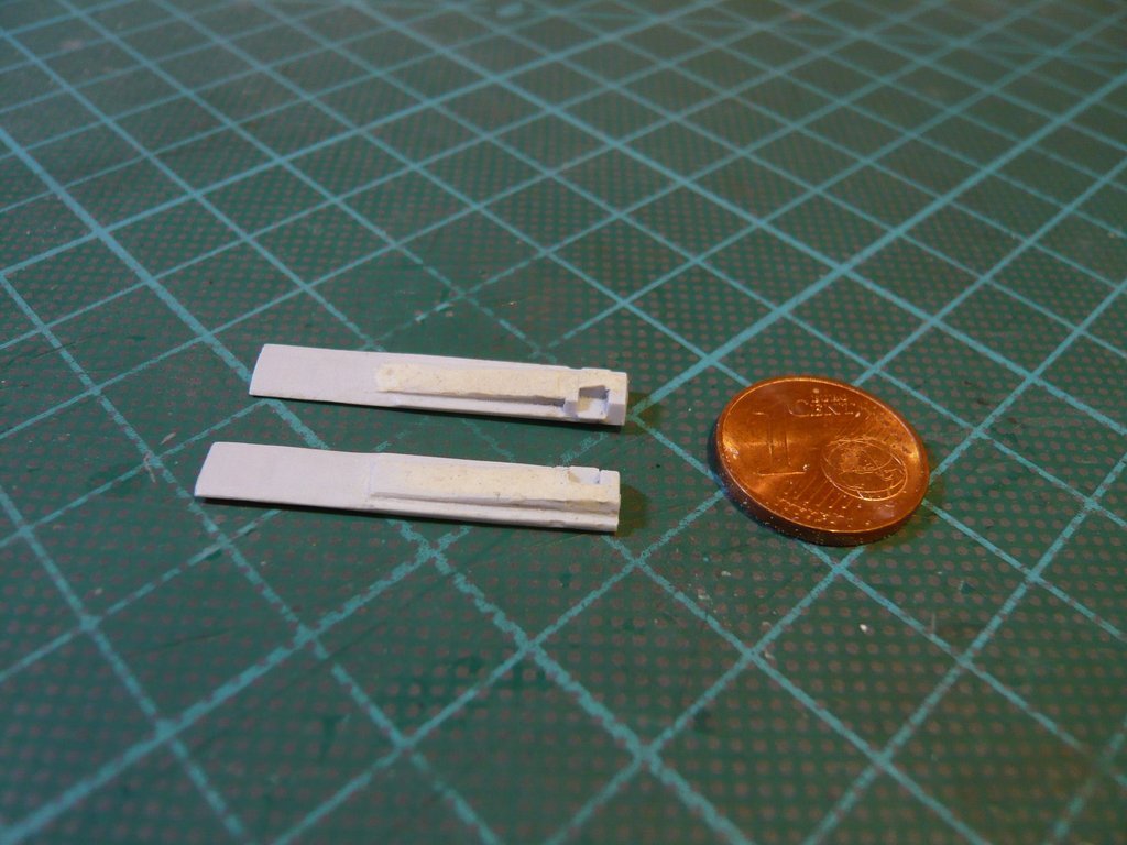 and then carefully sanded from all sides. The Thrust Struts are only temporarily layed up and have yet to be glued in. Then the front connecting bolt can also still be scratched. 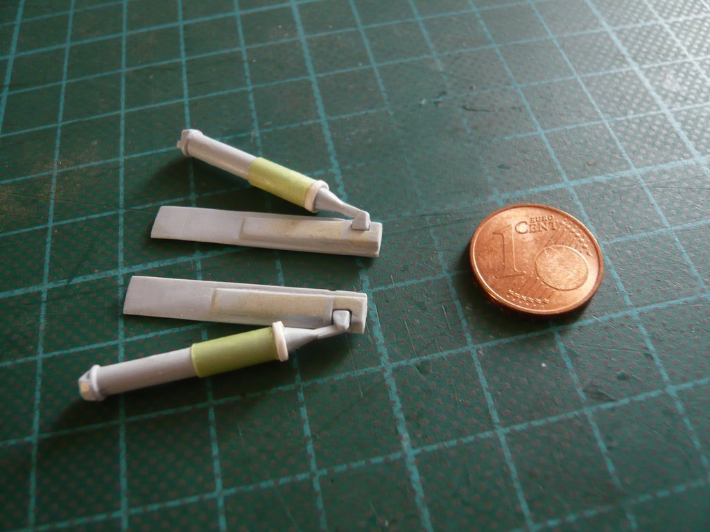 And finally, here is the ET with the temporarily layed up struts and Longerons.  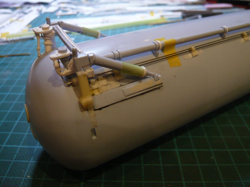 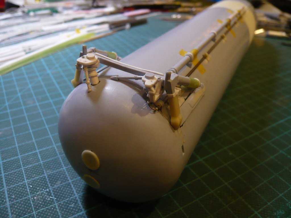 With that it's enough for today. 
__________________
Greetings from Germany Manfred Under construction: Launch Pad 39A with Challenger STS-6 (1:144)
|
|
#2074
03-22-2020, 10:41 AM
|
|||
|
|||
|
As ever, wonderful work Manfred and great explanations and photos.
Really good you are back on the forum. Regards Kevin
__________________
Normally the most advanced tech I use is a pencil.
|
|
#2075
03-22-2020, 05:09 PM
|
||||
|
||||
|
Thanks Kevin for your staying tuned, the journey can go on.
 Hello friends, for the masking of the connection areas of the ET Attachments before the Flour process, one interface is still missing, and that is the one between the ET Vertical Struts and the SRB Aft Attach Struts, Source: forum.nasaspaceflight.com (Jester) which were unfortunately not taken into account in both the Airfix Kit and the Newware Kit, which results in this gap, which of course should not exist there. 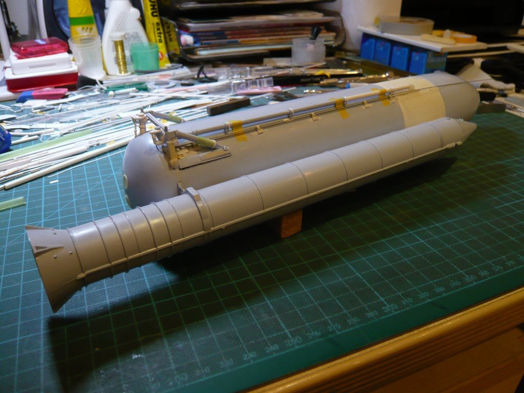 Via the local cable connections running in the Cable tray and through the Upper Strut, u.a. the ignition of the SRB Separation Motors took place, which initiated the separation from the ET after the burnout of the Boosters. As one can see from the following image, the round cladding of the Upper Strut cannot be overlooked, 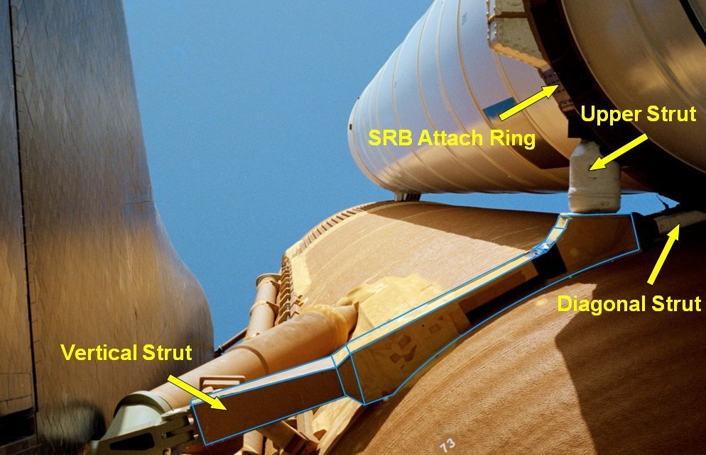 Source: forum.nasaspaceflight.com (woods170) and is not nearly just a puny thing like at the dainty Airfix Strut,  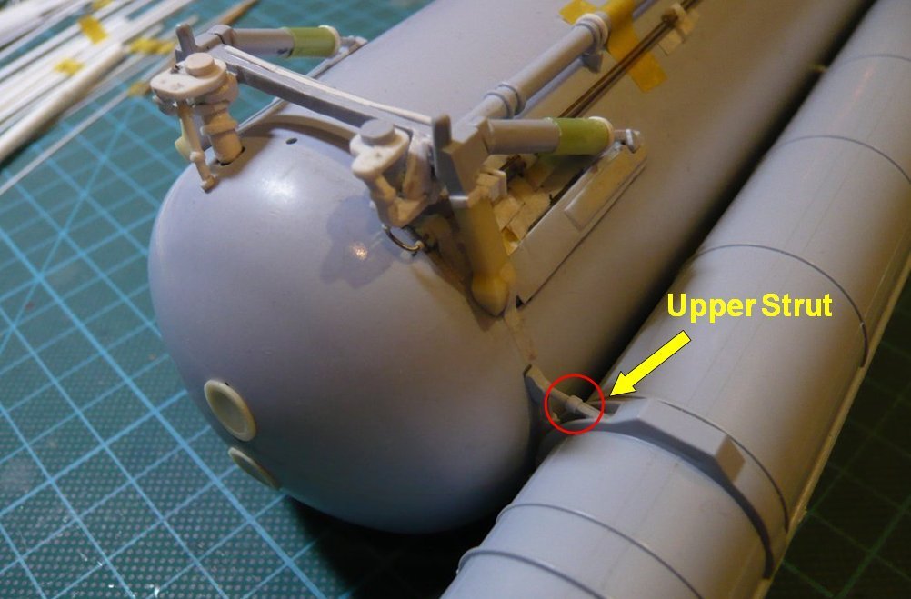 which can also be seen in this photo by Steve Patlan,  Source: live.staticflickr.com (Steve Patlan) who was close to the action at the time and has great photos in his albums.  Source: live.staticflickr.com (Steve Patlan) This comparison inspired me to show these details at the interface in a more real way, whereby I was starting with the cladding of the Upper Strut. But since I had already glued the struts at the right SRB, I've taken the struts of the left SRB and first removed the annoying bobble. 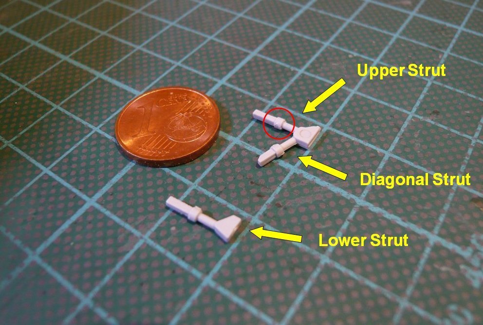 Then I've drilled off a Styrene Rod (Ø 3 mm) step by step up to Ø 1,4 mm, 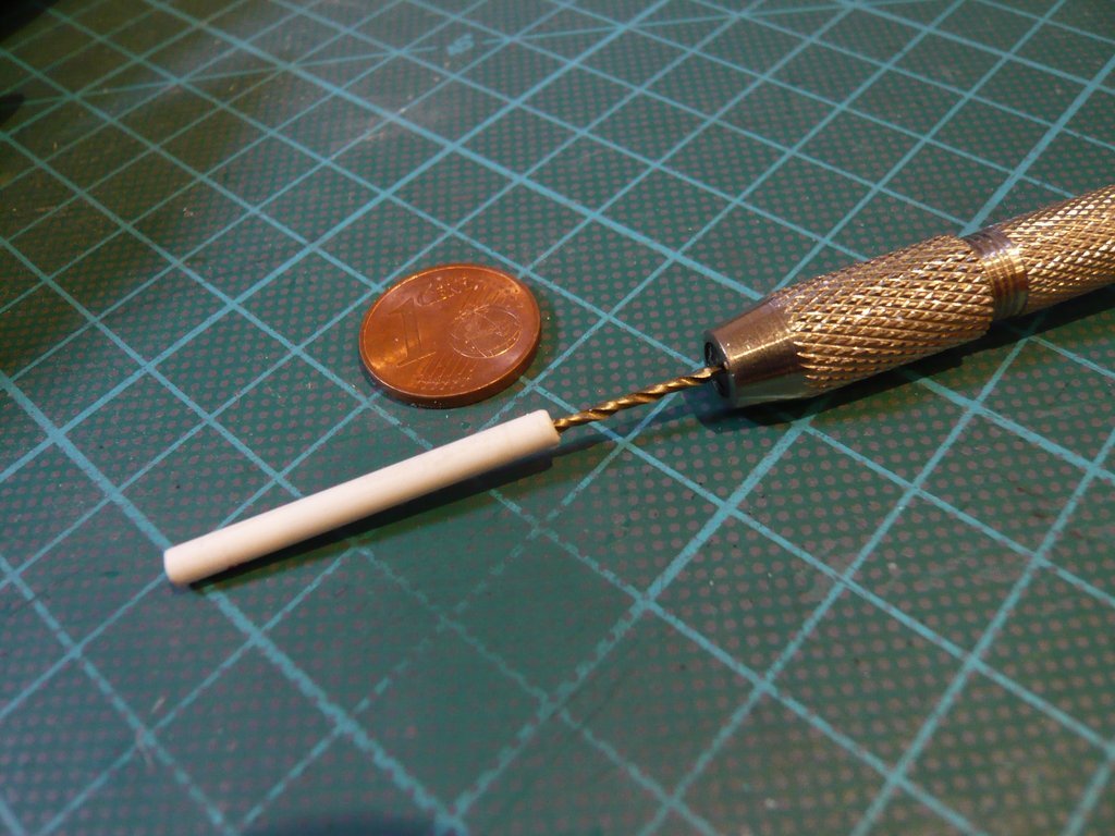 so that a separated sleeve of it could be pushed over the strut. In between there was placed a punched disc (0,25 mm, Ø 3,4 mm), 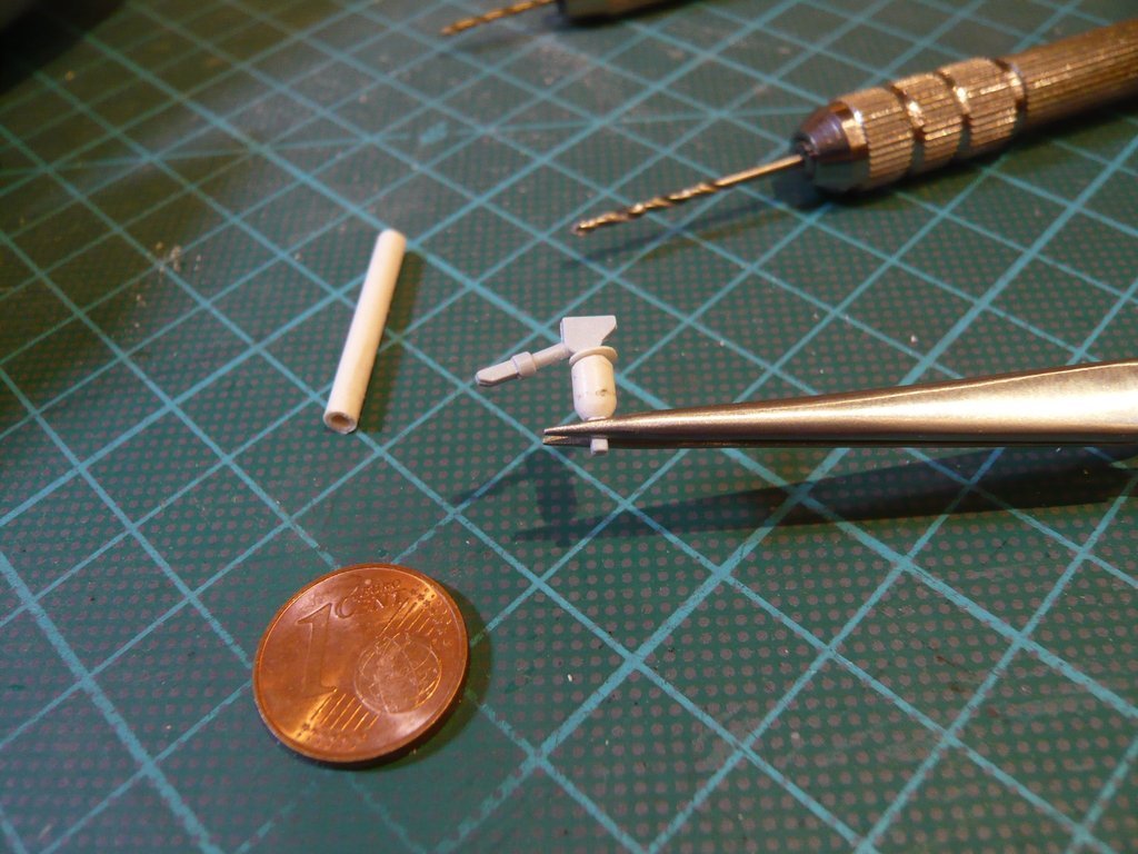 which then was glued together with the sleeve on the strut, which already looks more similar to the original strut. 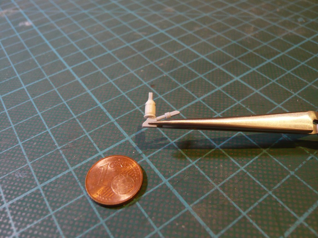 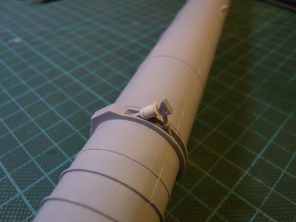 The same procedure I will now carry out on the right SRB Strut, for what I will carefully separate it off the booster.  And now once again to the connecting cable tray between ET and SRB Attach Ring, for what I once again did use this overseeable photo of the ET-32 ( STS-32) by George Gassaway, what I've turned by 90° for better orientation, from which I've also determined the dimensions (in mm) of the individual details.
__________________
Greetings from Germany Manfred Under construction: Launch Pad 39A with Challenger STS-6 (1:144)
|
|
#2076
03-22-2020, 05:11 PM
|
||||
|
||||
|
Therein one can also see well the green drawn TPS Cladding, which lies in front of the Cable Trays like an oblique ramp and should have a similar protective function like those of the elongated LH2/LO2 PAL Ramps in front of the cable trays in the middle and front tank area.
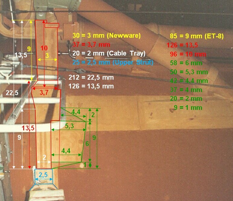 Source: georgesrockets.com (George Gassaway) With these dimensions I have drawn this sketch (1:1), 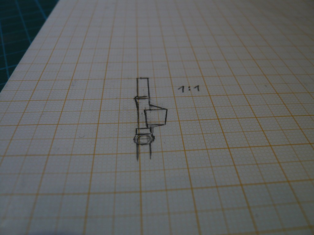 which I then have put onto the interface to try on, with which I can mark the masking areas on the ET. 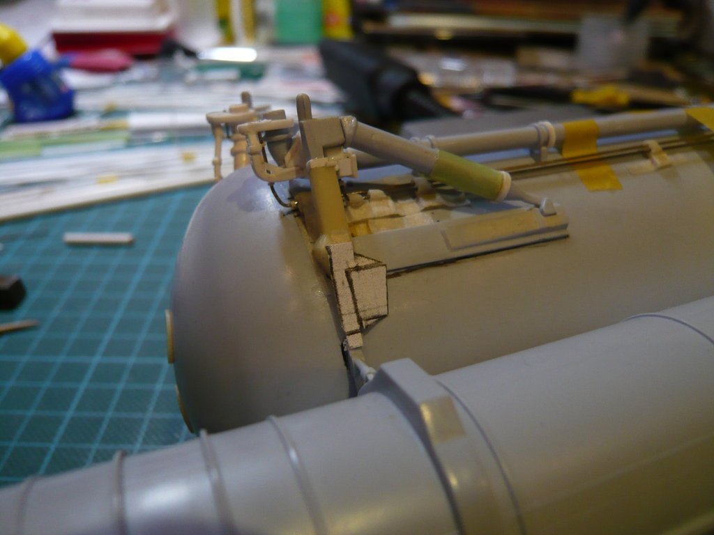 The remaining dimensions for scratching the parts I've determined from this side view, 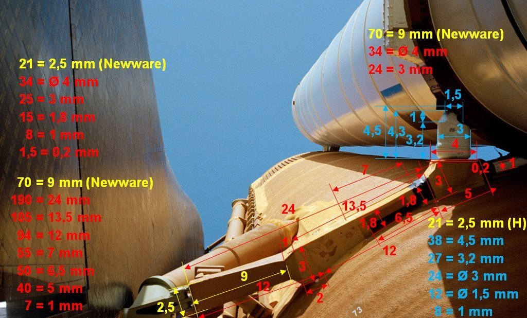 Source: forum.nasaspaceflight.com (woods170) wherewith again a further small step was done.
__________________
Greetings from Germany Manfred Under construction: Launch Pad 39A with Challenger STS-6 (1:144)
|
|
#2077
03-23-2020, 09:03 AM
|
||||
|
||||
|
Hello everybody,
in the meantime, the second SRB Upper Strut (right) has also been modified by the thicker sleeve, but the strut, unfortunately, could not be removed from the bonding without being damaged and therefore has to be lengthened somewhat, so that the distance of the booster from the ET is correct. 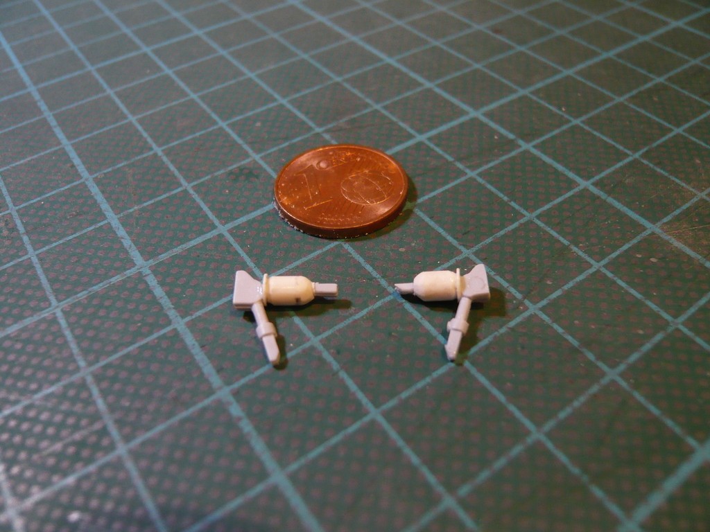 For the test fitting onto the ET, I was able to use it like this for the time being. Then I've marked the contours for the Longerons and Cable Trays, incl. TPS cladding, 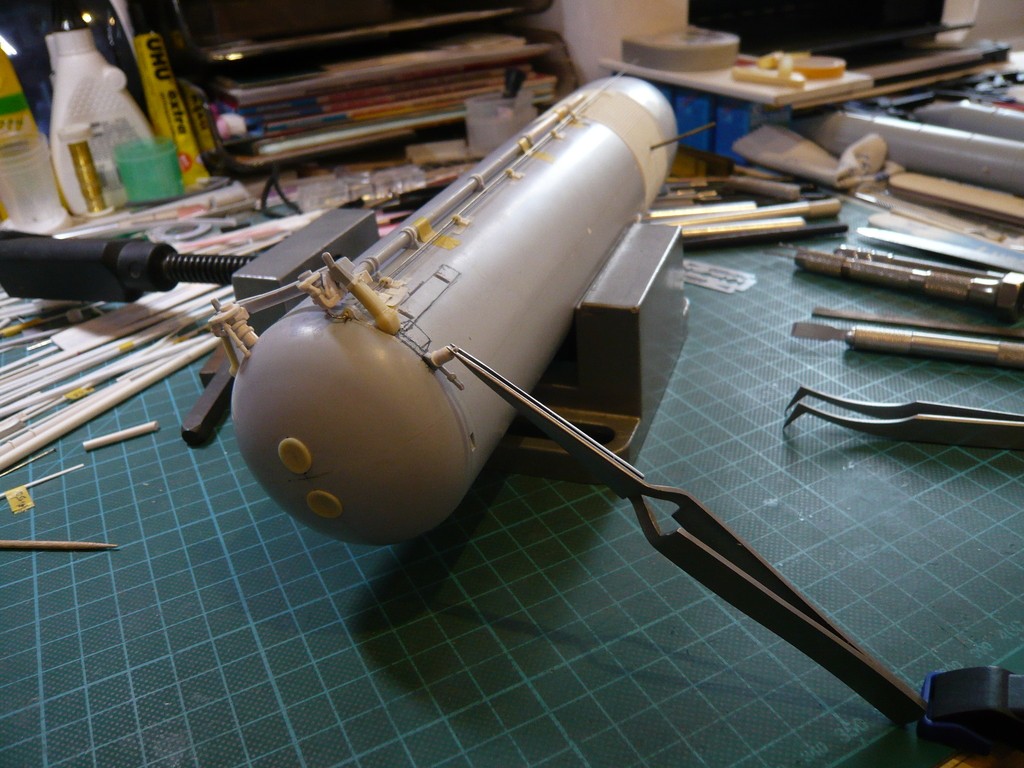 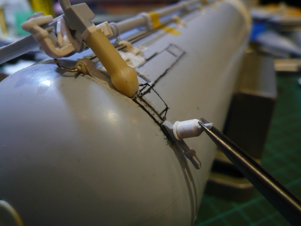 and then taped them off with tape so that I can expose the adhesive surfaces again after the flouring and priming/painting. 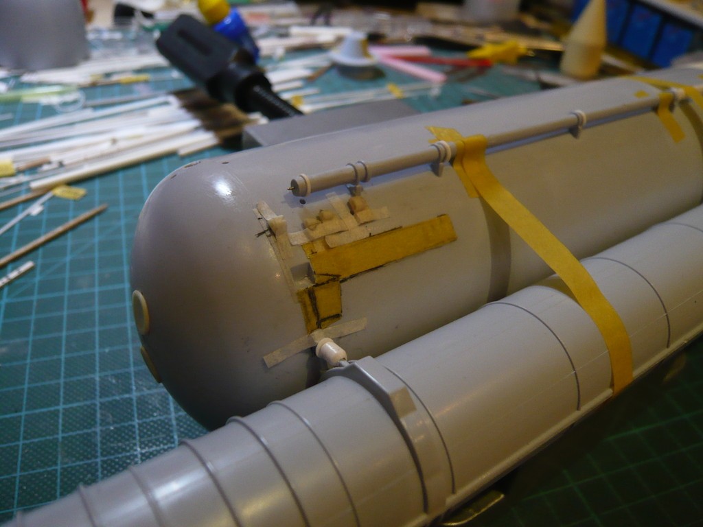 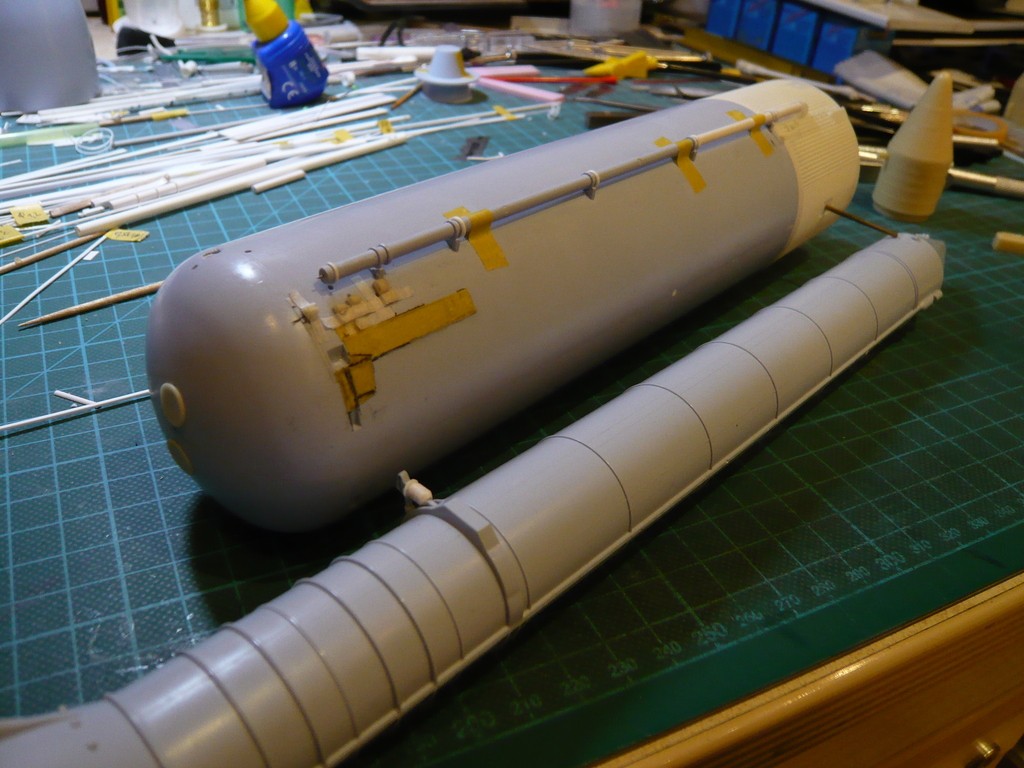 Then I took a closer look at and measured the SRB front parts (SRB Forward Skirts) from the Newware Kit, the surface of which is surprisingly finely structured and therefore looks much more real than that smooth from Airfix, 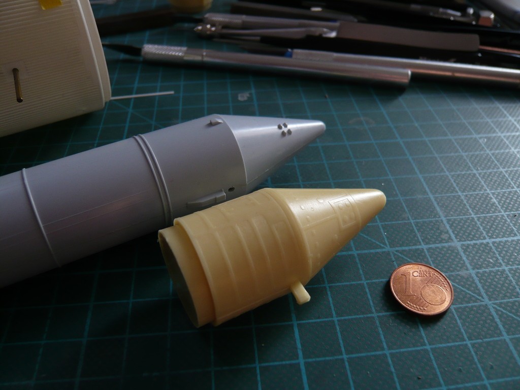 whereby they come pretty close to the original. 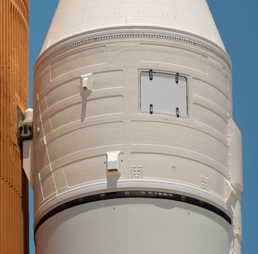 Source: NASA Since the Newware Kit is specially designed for the Revell Shuttle Stack, the question arose whether the SRB Forward Skirts would also match the Airfix-SRBs. But since the diameters of the SRBs of both kits are surprisingly the same (Ø 26 mm), I was relieved and have carefully cut off the front part with the fine saw. 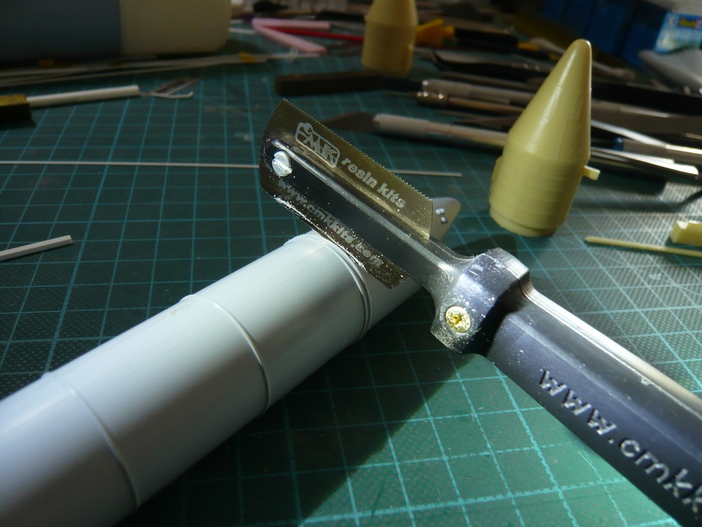 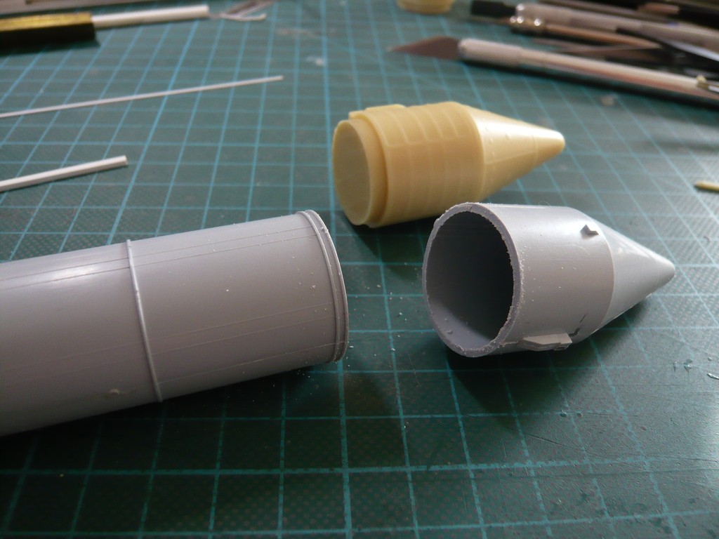 And lo and behold, the Newware Forward Skirt makes a good match with the Airfix booster  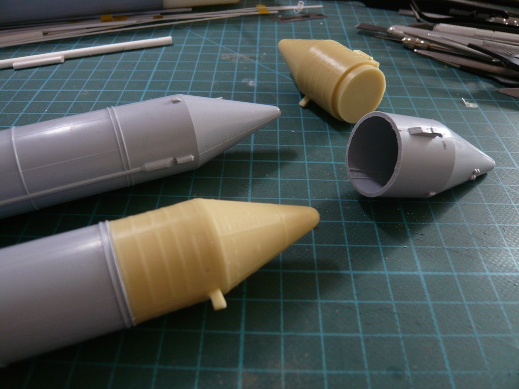 Now I just have to drill the hole for the brass support rod in the right place and take care that the drill does not run away in the Resin part.  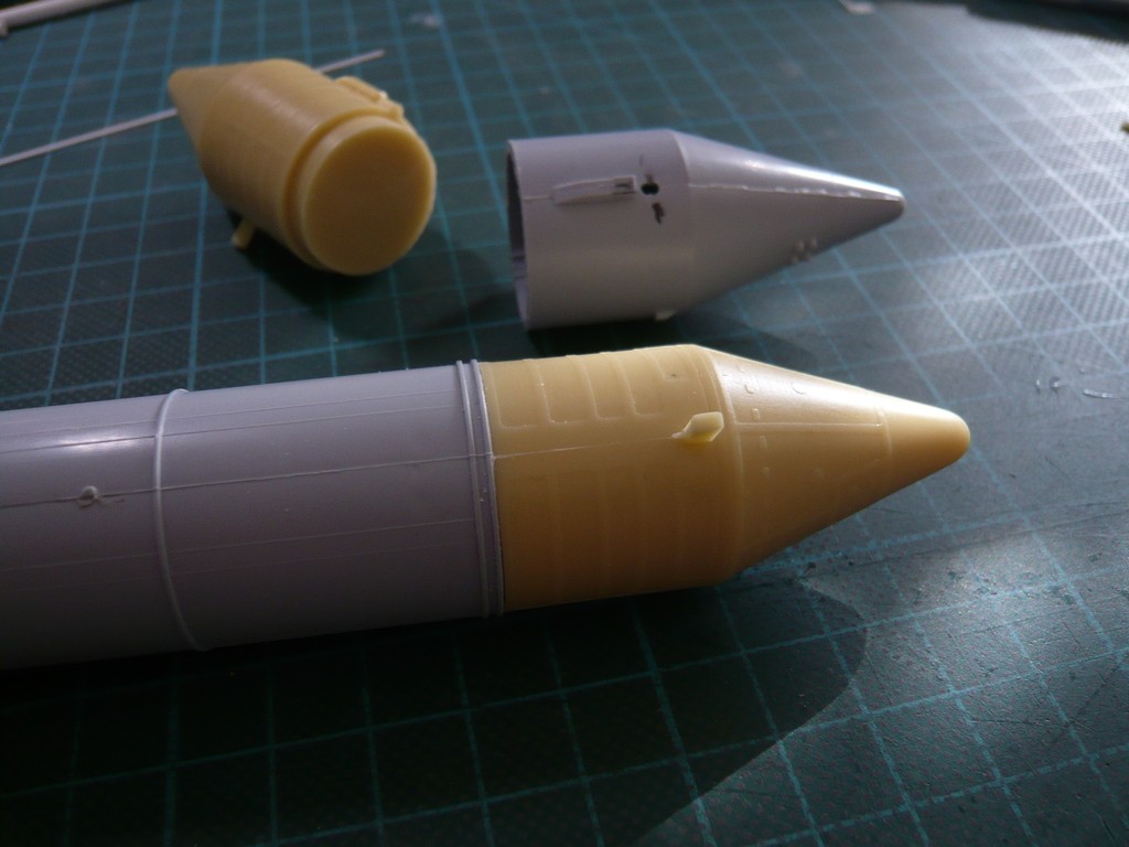 So I'm still trying to figure out how to do it best ... are there any thoughts?  We will see ...
__________________
Greetings from Germany Manfred Under construction: Launch Pad 39A with Challenger STS-6 (1:144)
|
|
#2078
03-24-2020, 01:53 AM
|
||||
|
||||
|
Hello everybody,
BTW, I actually don't need to drill 25 mm deep, because 5 - 10 mm should also be enough if I shorten the brass support rod on both sides accordingly. Therewith the boosters' forward attachment point should be fixed sufficiently and, together with the rear SRB Aft Attach Struts, ensure a stable three-point support of the boosters. This is this circled wedge-shaped Fastening part (SRB/ET Forward Attach Fitting) between the ET and the SRB, in each of which is a Separation Bolt, which is blown up together with similar bolts in the rear SRB struts when the SRBs are separated from the ET and thus releases the booster. 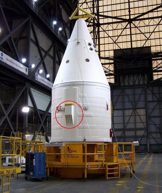 Source: NASA 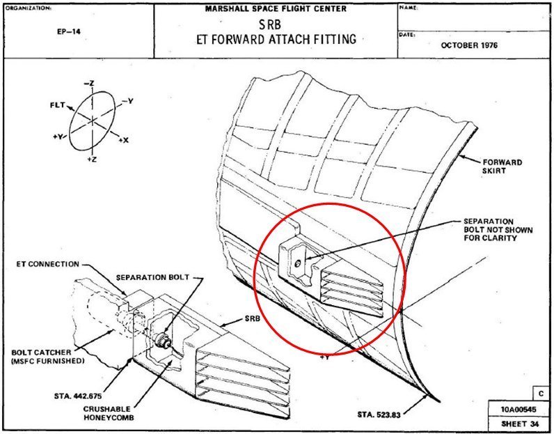 Source: Marshall Space Flight Center, Space Transportation System HEAR No. TX-116 As one can see in this image, this fastening wedge is in place on the Airfix booster, but it is missing on the Newware SRB Forward Skirt, what in turn proves that apparently no kit is perfect. 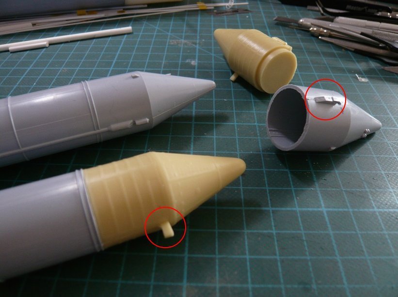 Therefore I will scratch this wedge-shaped part and glue it to the attachment point behind the drilled hole for the support rod, with which the attached booster will be glued onto the ET, which should ensure a sufficient hold.  And these 5 - 10 mm deep drilled holes should be carried out by hand with the appropriate caution and care, I hope so.
__________________
Greetings from Germany Manfred Under construction: Launch Pad 39A with Challenger STS-6 (1:144)
|
|
#2079
03-24-2020, 12:28 PM
|
|||
|
|||
|
Spacerunner's Master Class continues! HOORAY!!! Go, Mani, go!!!
 Kind regards from Vreden and stay healthy! Marcell
|
|
#2080
03-24-2020, 12:59 PM
|
||||
|
||||
|
Thanks Marcell for coming back to me.
I was already worried about you, my friend ... My journey is far from over, so stay tuned and take care, especially keep your safety distance!!!
__________________
Greetings from Germany Manfred Under construction: Launch Pad 39A with Challenger STS-6 (1:144)
|
 |
|
|


 Linear Mode

