


|
|
|
#2241
 08-22-2020, 01:49 AM
|
||||
|
||||
|
Thanks my friend for looking in on me,
 and stay tuned. and stay tuned.I'm holding on to my dreams and go on my way again.  
__________________
Greetings from Germany Manfred Under construction: Launch Pad 39A with Challenger STS-6 (1:144) 
|
|
#2242
08-24-2020, 04:40 AM
|
||||
|
||||
|
Hello everybody,
with this update I want to briefly inform you about the current status.  In the meantime I have thought of a solution for laying the first four lamps in the red circle on the MLP-Side 1, whereby the LED wires are laid in such a way that they cannot be seen afterwards.  In an intensive exchange of ideas with my German Raumcon friend McPhönix, who built the ingenious Mega power bank for the complete pad lighting for me, we agreed upon a solution, in which the cabling between the power bank and the MLP takes place via the front Pedestal at the right-hand corner of the MLP.  Who would like to find out more about the structure of this power bank can look into his thread Lighting of models, unfortunately only in German.  After repeated detailed examination of the previous splitting of the three LED circles on the MLP-Side 1 I came across a tricky problem considering the sometimes very cramped spaces under the roofs of the MLP, related to the Lamps 5-7 in the yellow circle,   Source: retrospaceimages.com - STS-6 High-Res. Image Library which I have marked with the yellow arrow in this image.   The following two images once again show the cramped conditions circled on site.   After the laying the first four lamps (1-4) of the yellow line, I would then have to climb up with the last three lamps (5-7) from the ceiling above the lower Access Platform along the stairs there up to the upper Access Platform above the LH2 Valve Skid followed by pulling the strand with the three lamps through a real eye of a needle between the support struts of the LH2 Transport Line, which would be almost impossible. In addition, the LED wire would then hang freely in the space in front of the tubes on the MLP wall.  To find a way out of this dilemma, I changed the division of the LED circles once again, which can be seen in the following images. Therefore I've extended the red circle by a lamp, 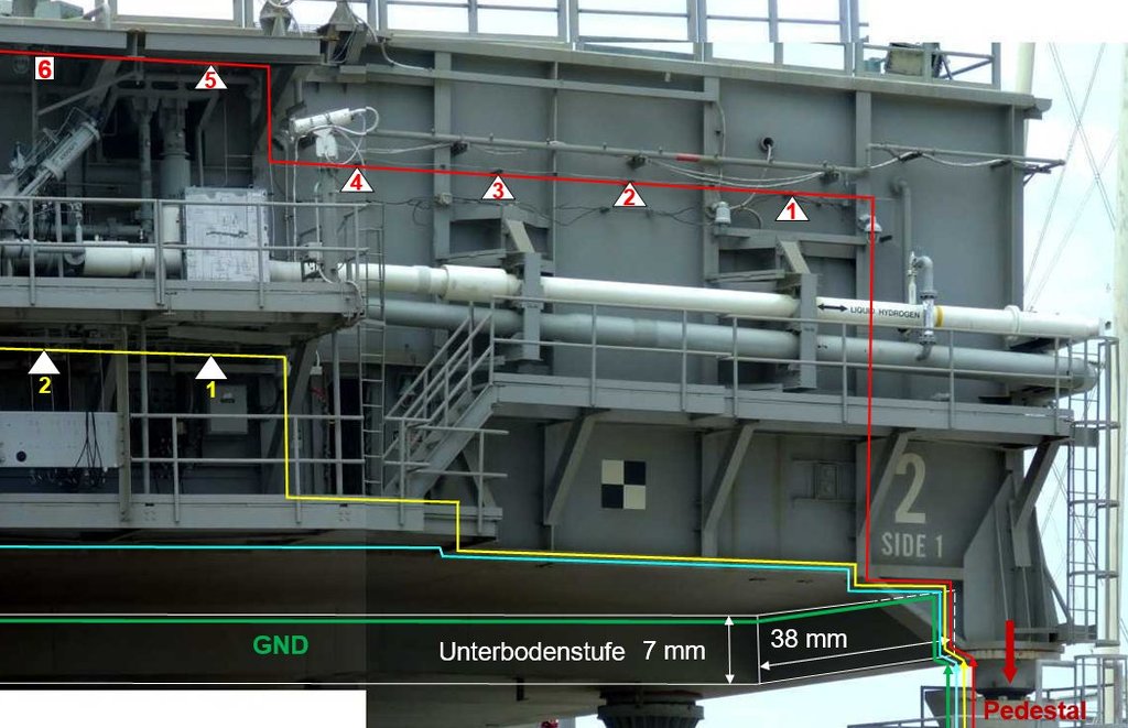 Source: capcomespace.net which now ends with the Lamp 8 at this needle eye and is led on the rear wall to the return conductor (GND). Thus the yellow LED circle only has still four lamps (1-4). The remaining two lamps (6/7) of the originally yellow circle now form the beginning of the light blue circle (1/2), 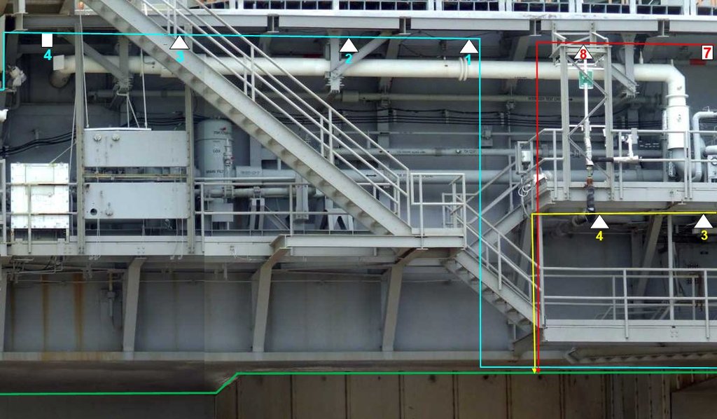 Source: capcomespace.net which now includes eight lamps. 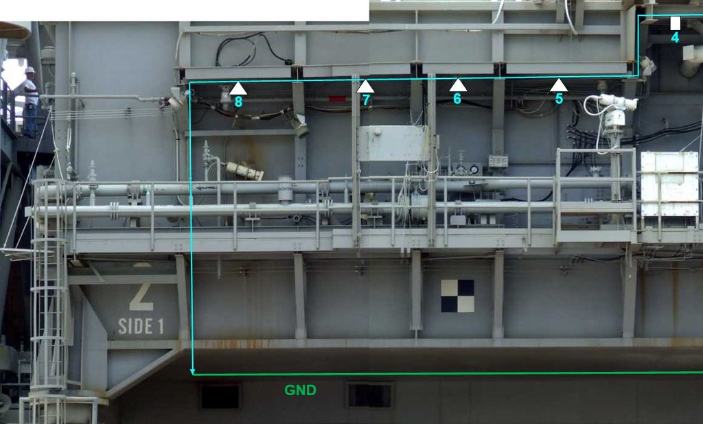 Source: capcomespace.net With this redistribution, the laying of the LED circles should now be a bit easier, I hope so.
__________________
Greetings from Germany Manfred Under construction: Launch Pad 39A with Challenger STS-6 (1:144)
|
|
#2243
08-29-2020, 02:27 PM
|
||||
|
||||
|
Hello friends,
let's go on. And therewith back to the first LED circle (1-8, red), of which the first four lamps are somehow attached to the MLP wall, the question is only how?   On this already shown part from a photo montage from the Side 1 of the MLP-2 I had conjectured inlet pipes for the lamp cords at the fastening points of the lamps, laying in the middle of the wall's frames.   Source: capcomespace.net That's why in a first version I used a Styrene rod (Ø 0,7 mm) to hold the lampshades, which I've glued with UV adhesive onto the lampshade.  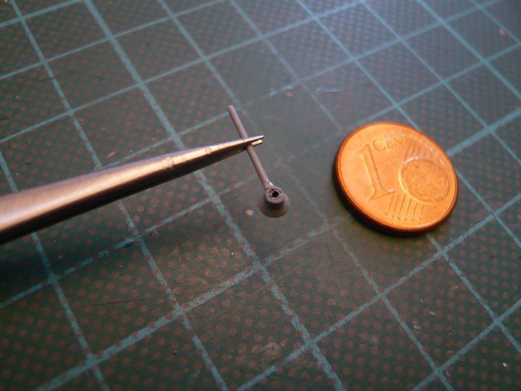 To facilitate tests for the assembly and cabling of the first four LED lamps on the MLP wall, I made a true-to-scale copy of Side 1 from David Maier's paper kit as a template and then glued four vertical struts from the used styrene profiles,  as well as temporarily placed a lampshade, which should not lie against the wall directly. as well as temporarily placed a lampshade, which should not lie against the wall directly.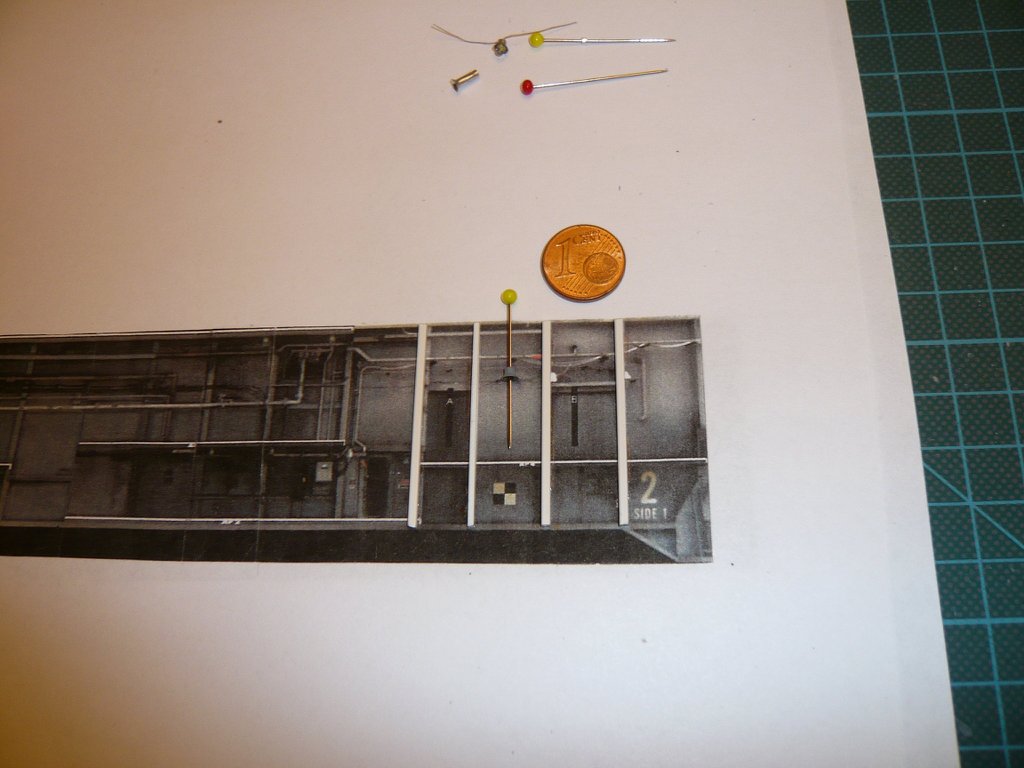 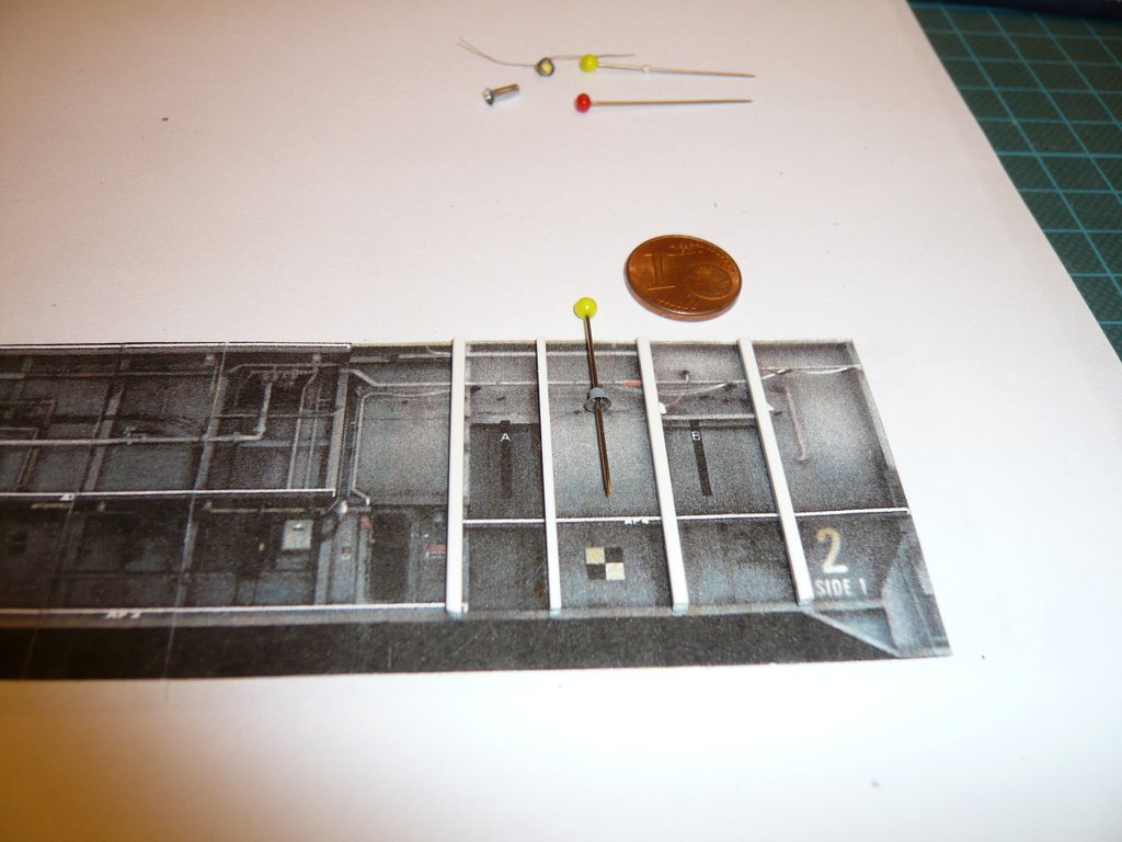 Here the lamp with the holding rod is plugged into the wall, which would make this a useful attachment variant. 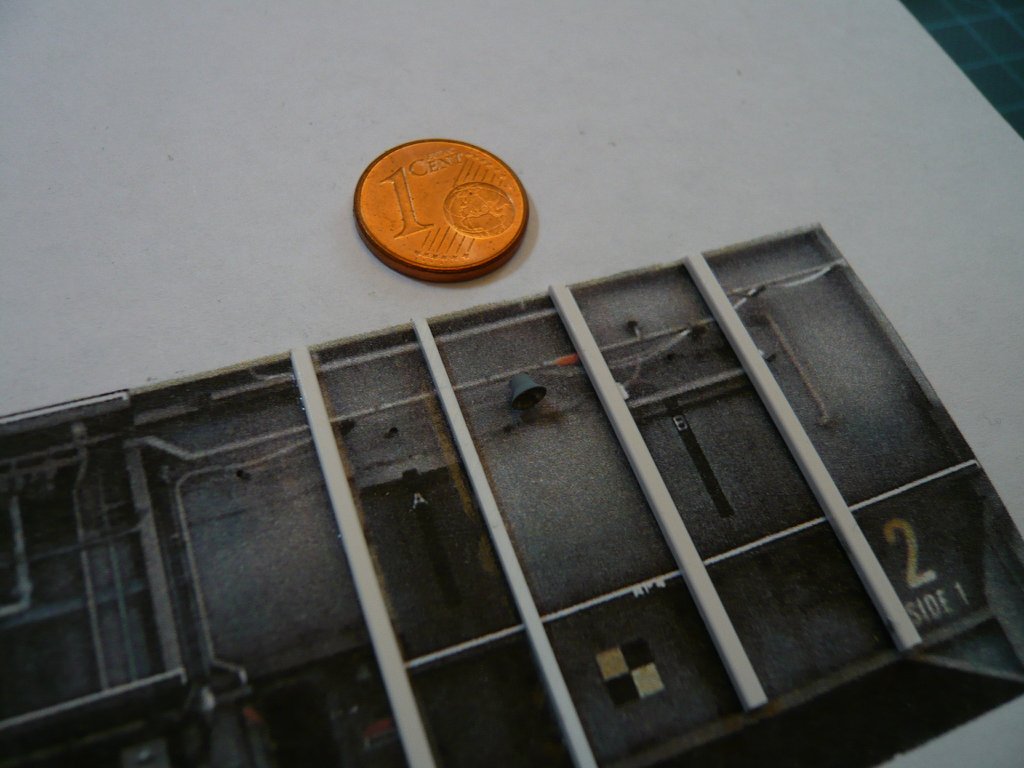 In the meantime I've remembered the great Launch Pad 39A Reference Photos by Troy McClellan, on which one can see at maximum resolution (3x click) that those are not tubes but Angle profiles to which the lamps were attached during the early STS missions, which were later replaced by other lamps like these ones here. 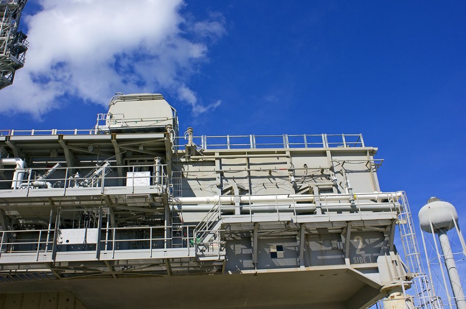 Source: Troy McClellan On this image section I've measured some details and found that the angles, scaled to 1:160, are only 0,4 mm x 0,4 mm "large" and protrude slightly beyond the wall struts towards the front, i.e. they should be approx. 2 mm long, thereby the lampshades (Ø 2,8 mm) would be slightly in front of the wall. [img]  [/img] [/img]But such small angle profiles there are not available neither made of styrene nor brass, whereby the smallest brass angles are 1 mm x 1 mm, which would be a bit too big.  So I was thinking about how and from what one could scratch such small angles. But more on that tomorrow, have a nice day.
__________________
Greetings from Germany Manfred Under construction: Launch Pad 39A with Challenger STS-6 (1:144) Last edited by spacerunner; 09-01-2020 at 04:46 PM.
|
|
#2244
08-30-2020, 03:12 AM
|
|||
|
|||
|
I'm sitting in front of the screen with my jaw on the floor. You continue to amaze me! But yes, I do think it would be possible to incorporate the wires into the design. If you look at the real thing the wires are indeed visible on the outside, so why shouldn't they be visible on the model, too. That shoudl mak things "a bit" easier.

|
|
#2245
08-30-2020, 05:55 AM
|
||||
|
||||
|
Thanks Marcell for your nice compliment and your well-meant tipp.
I will think about it.
__________________
Greetings from Germany Manfred Under construction: Launch Pad 39A with Challenger STS-6 (1:144)
|
|
#2246
08-30-2020, 06:00 AM
|
||||
|
||||
|
Hello everybody,
and back to the small angles. First I've tried to convert the smallest Evergreen-H profile (1,5 mm x 1,5 mm) into an angle. 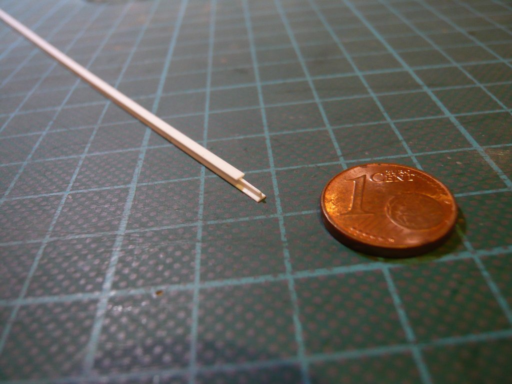 which after several cuts was 0,7 mm x 0,7 mm, but with legs 0,2/0,3 mm instead of 0,1 mm.  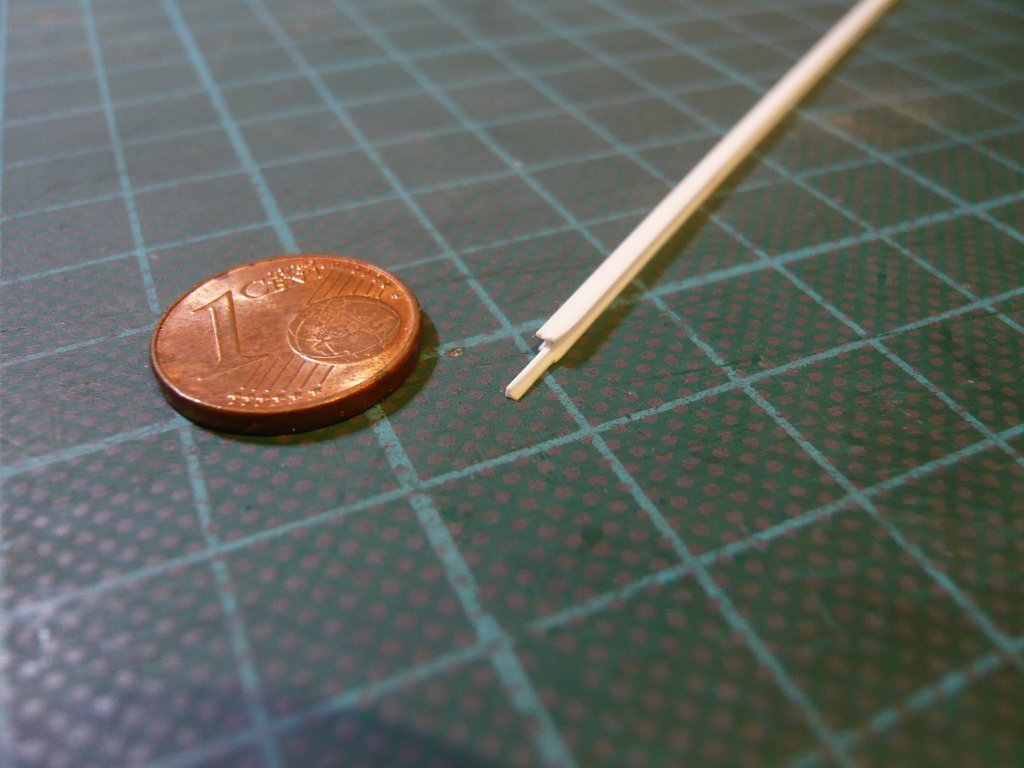 Then I remembered the Gutters on the MLP upper deck, for which I used Aluminum sheet (0,1 mm). So it was worth a try to make a possible small angle out of it, although the thought of it may seem rather crazy ... As a bending aid, I had thought of steel rulers (approx. 0,5 mm), which should enable a similarly small leg length. No sooner thought than done! 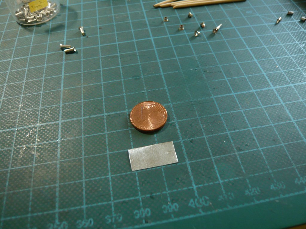 Since it is almost impossible to immediately bend a 0,5 mm narrow strip at right angles, I've started with a lot of overhang and then clamped the piece of sheet metal onto a sheet of steel, 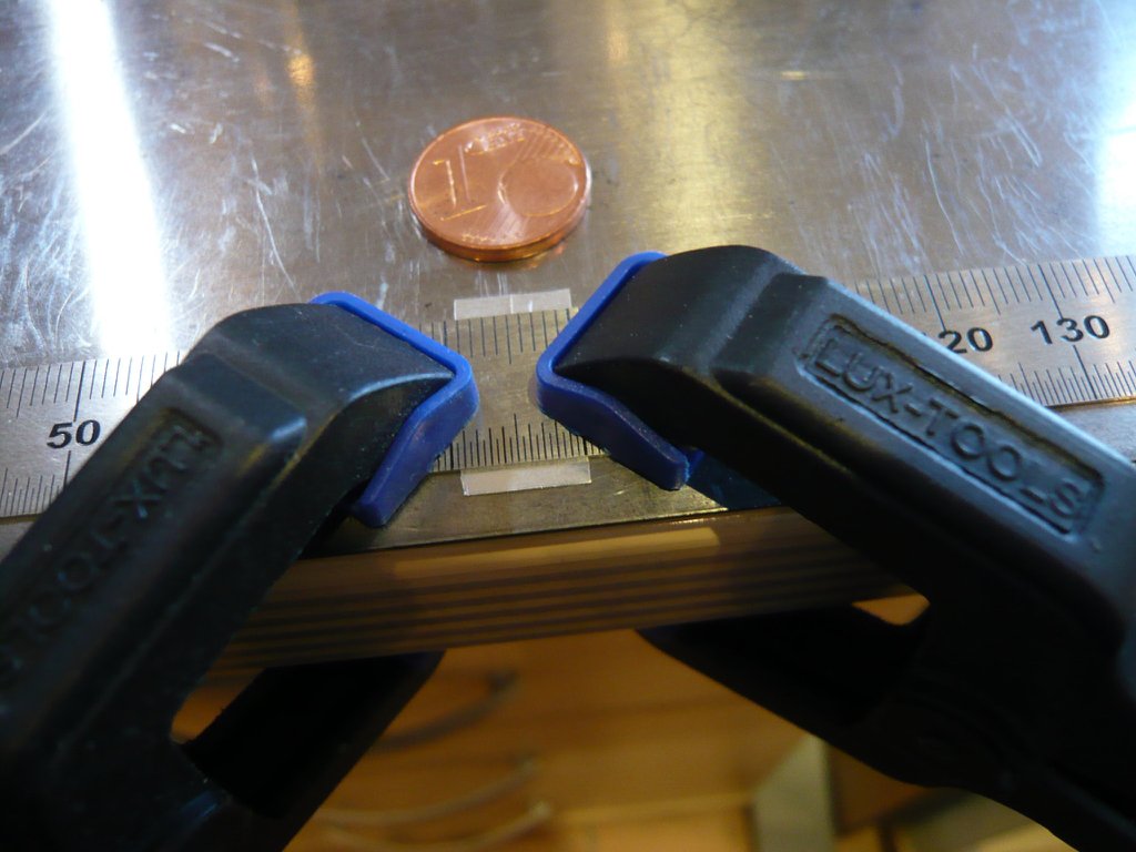 and have bent this strip vertically upwards. 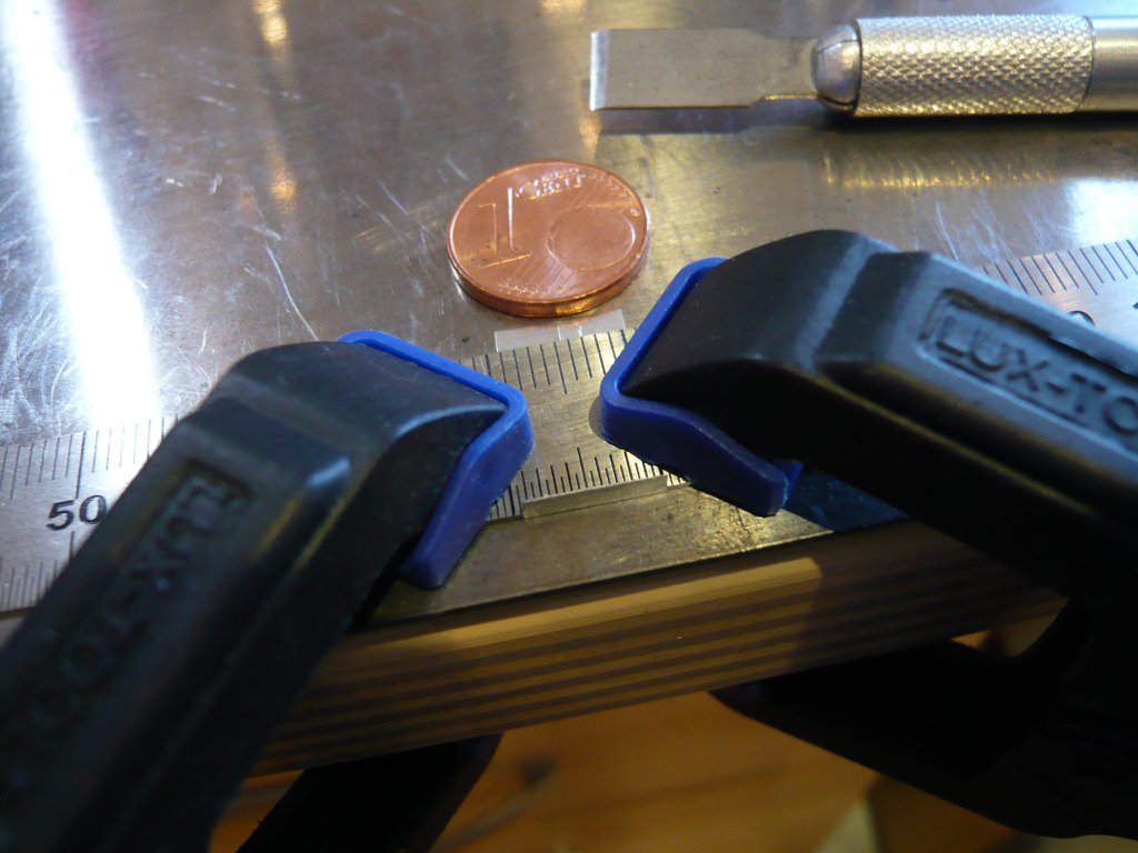 Then I've clamped the angled sheet metal upright between two steel rulers, 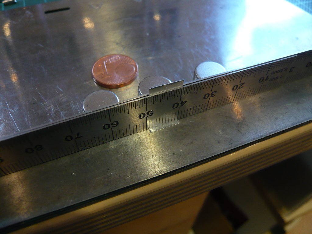 and have bent the strip up and down several times until it broke off. Then I've smoothed the breakline a bit,  wherewith one leg was already done. 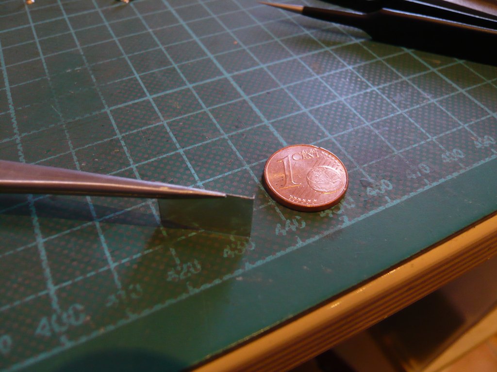 Then I've wedged the bent leg between the rulers, 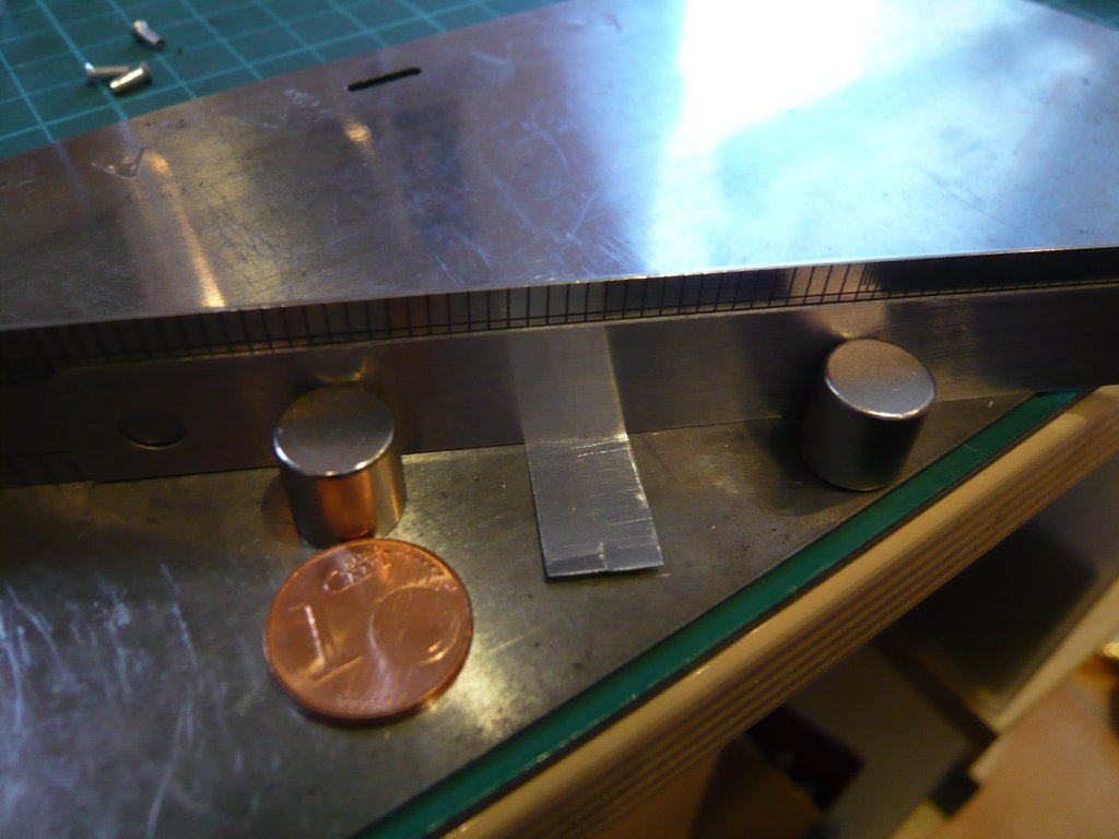 and have broken off the remaining strip in the same way. 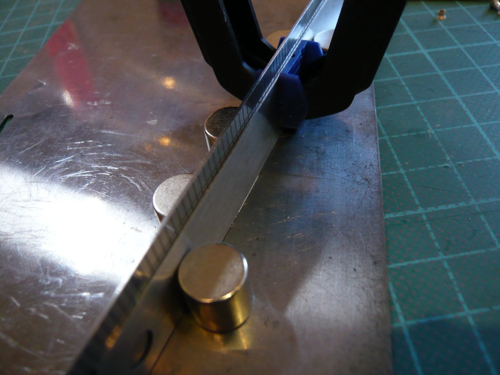 Thereby the angle was finished, was about 0,7mm x 0,7mm and looked quite passable. 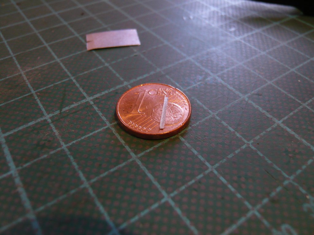 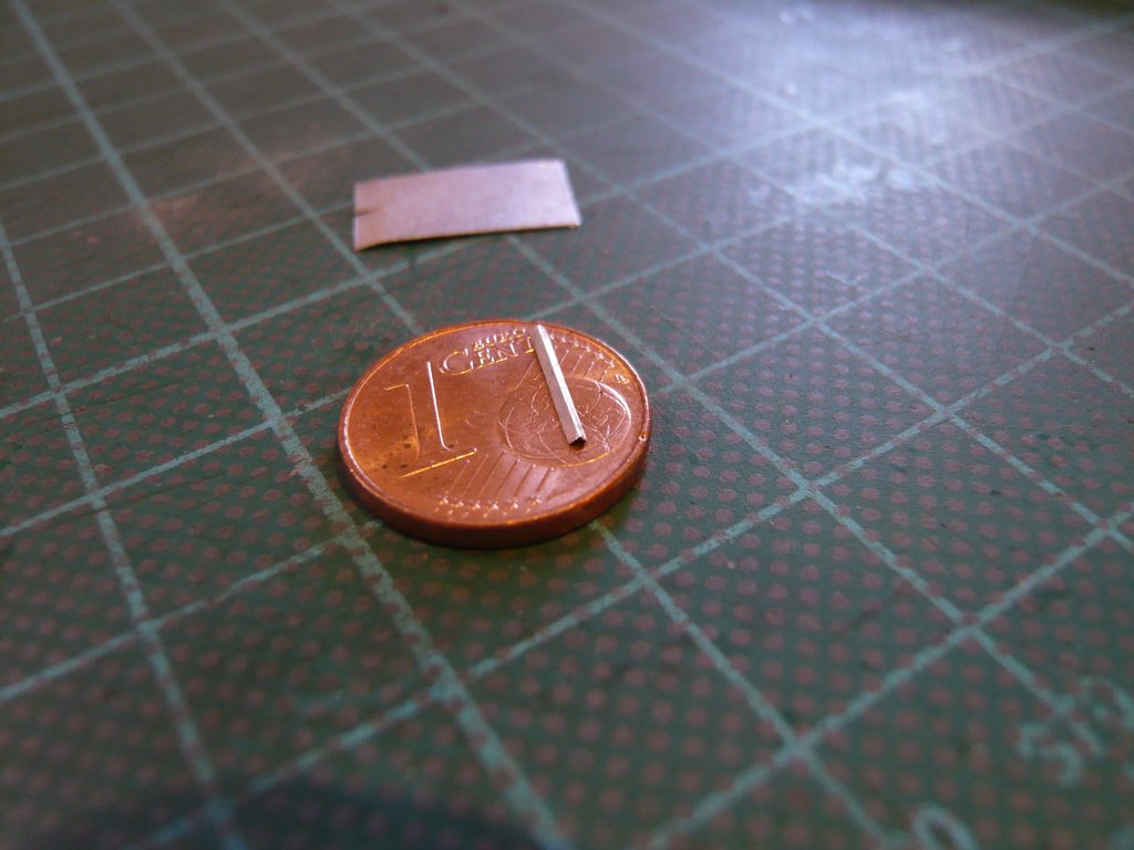 And this is how the angle at the lampshade would look. 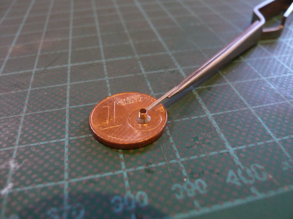 Now I'm curious what you're thinking about it?
__________________
Greetings from Germany Manfred Under construction: Launch Pad 39A with Challenger STS-6 (1:144)
|
|
#2247
09-04-2020, 04:36 PM
|
||||
|
||||
|
Hello everybody,
but this variant with the folded aluminum bracket will probably not win the race, because it does not seem stable enough to me and the effort seems nearly overdone too. Therefore it was more of a feasibility test than seriously meant. In addition, I really have to rein my mania for crazy details and concentrate on striking details and leave out less important ones. And with these four lamp holders, the last detail is less important, but rather that they serve the purpose and hold the lampshades. And with a length of approx. 2 mm, they can hardly be seen behind the lampshades anyway ...  I was rather more likely a bit too euphoric about my discovery that ultimately it was angular profiles what immediately has started my scaling and scratch generator. Therefore a simpler and more stable solution has to be found, as I have already demonstrated with the round rod. For comparison I have added a Brass angle profile (1,5 mm x 1,5 mm), which, however, seems too big to me in terms of proportion.  In short, I will probably use an Evergreen rod (0,7 mm x 0,7 mm), which fits well with the lampshade, is easier to glue together and should allow a stable hold.  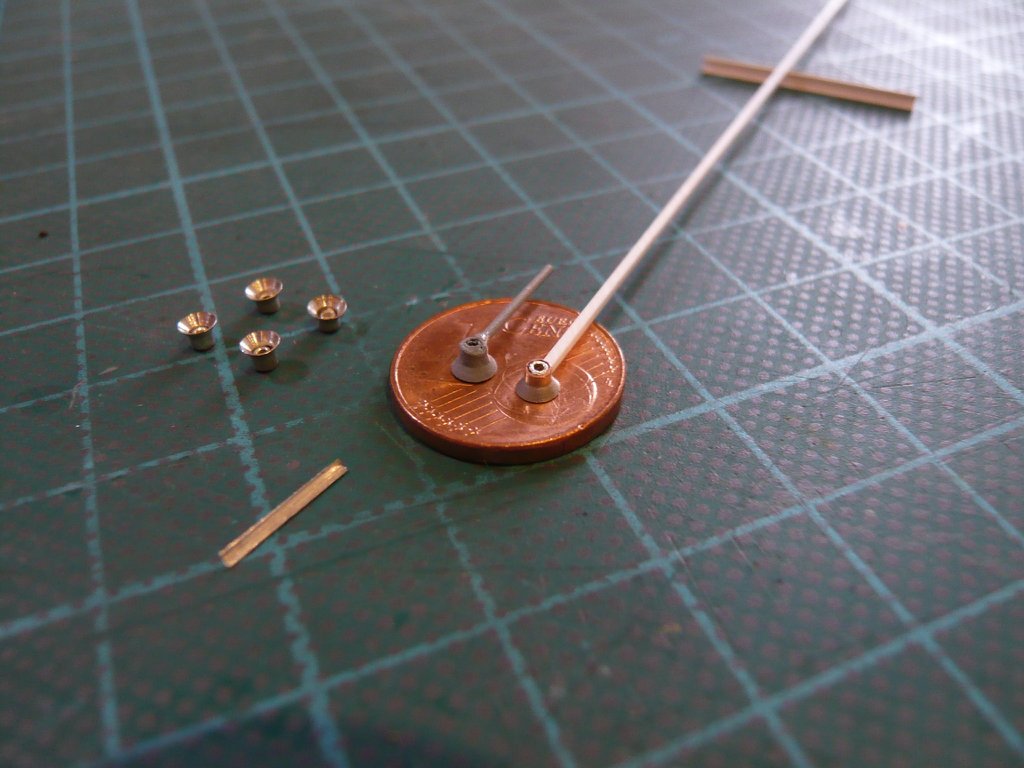 Let's see ...
__________________
Greetings from Germany Manfred Under construction: Launch Pad 39A with Challenger STS-6 (1:144)
|
|
#2248
09-07-2020, 05:02 PM
|
||||
|
||||
|
Hello everybody,
finally, the wires (0,1 mm) with the LEDs (0401, 0603) have still to be threaded into the prepared lampshades and glued with UV glue whereby they are sealed and kept safe forever. 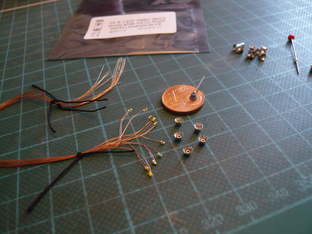 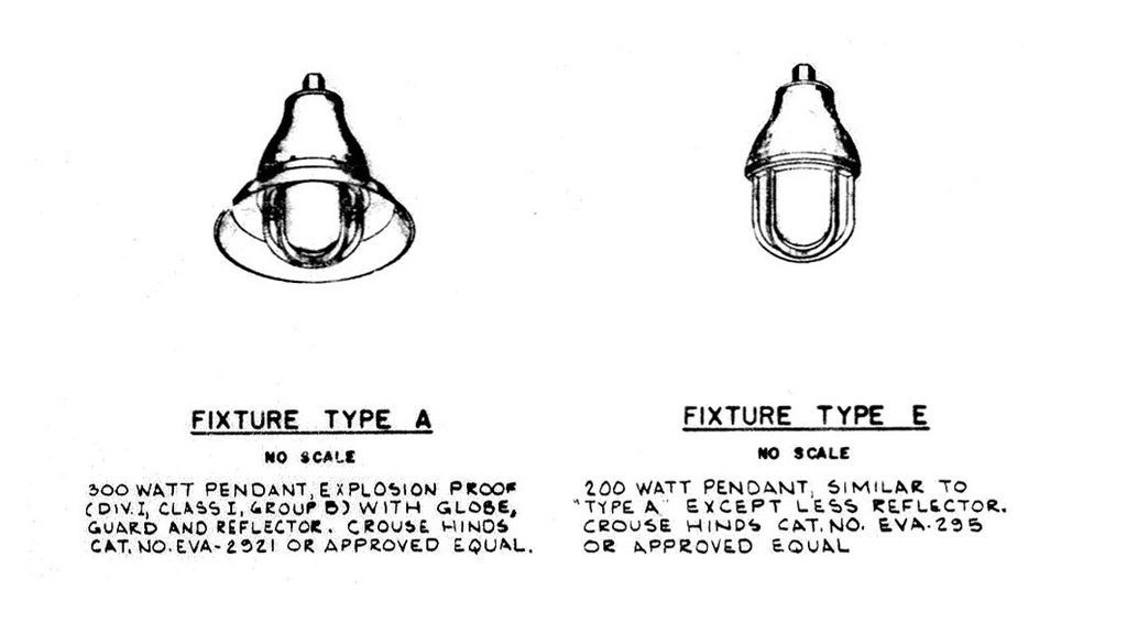 Source: NASA Besides to these two lampshapes as on the MLP-Side 1, there are each on the RSS and on the transition from the FSS lots of these arc lamps, which were mostly mounted on the handrails, 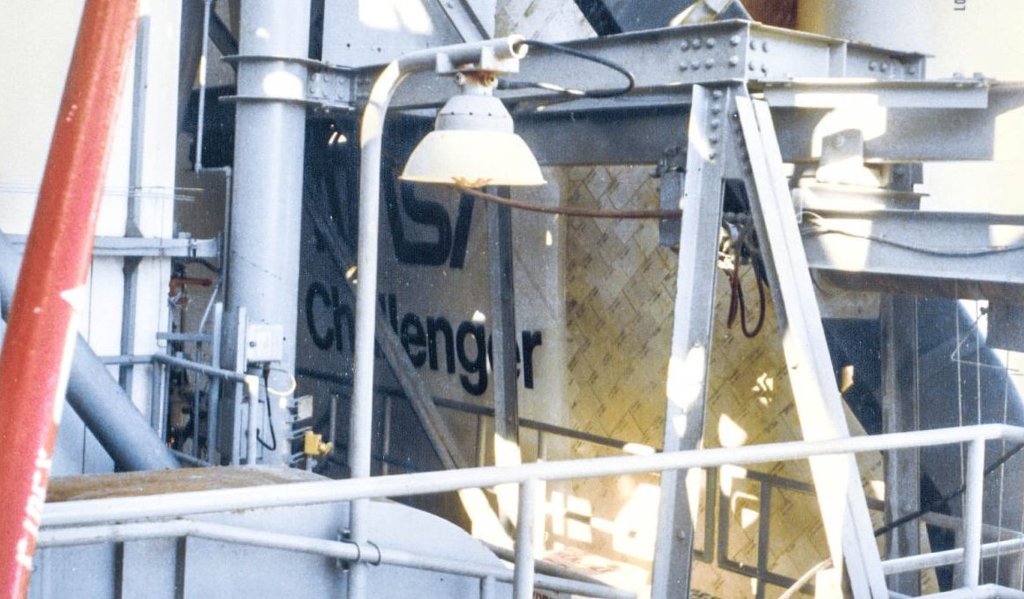 Source: James MacLaren (39B) NASASpaceflight.com whose rustic spherical shape from the Revell Launch Tower Kit I've already "admired" during my first lamps stocktaking analysis.  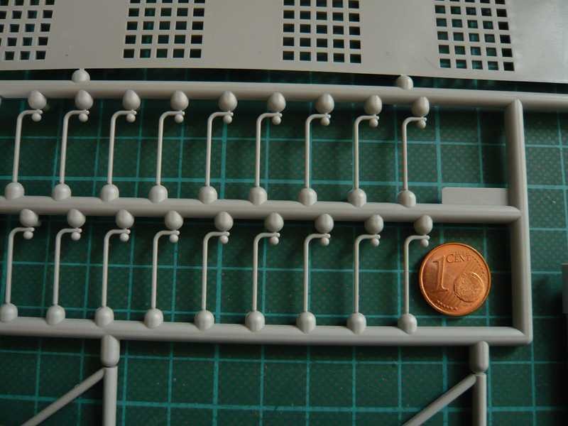 It looked already better with my lampshade, but compared to the lampshade, the stanchion with Ø 1 mm seemed to be oversized to me. 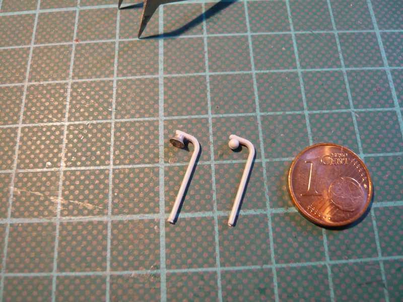 On the basis of this photo of my Pad 39B expert James MacLaren, the dimensions could be estimated fairly precisely, using the diameter of the MLP lampshades (Ø 2,8 mm). Only the length of the upper pipe bend (3,1 mm?) should be a little longer due to the shortened perspective. 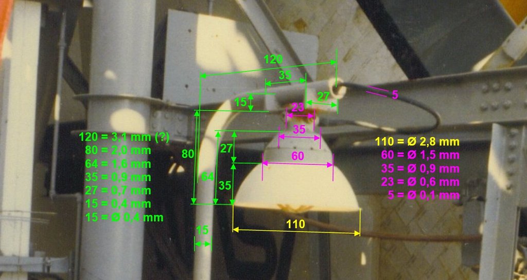 From this it can be seen that the curved stanchion with Ø 0,4 mm may actually only be about half as thick as that of the Revell lamp, which I had suspected. 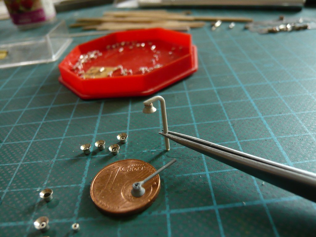 In order to stay roughly on scale, I will use a brass tube with Ø 0,5 mm (0,09 mm wall thickness) into which I will pull in the two LED wires (0,1 mm) expediently before bending the pipes, because this is not impossible in the bent state, 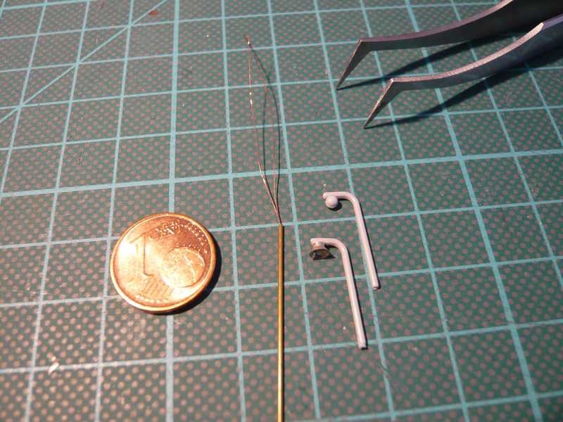 but much more difficult is what a stressful test unfortunately showed me impressively.  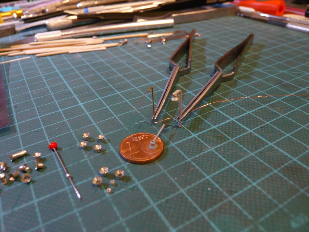 And with a little bit patience and a steady hand, one can even scratch the cable loop on this arc lamp, making the lamp come pretty close to the original in my opinion. 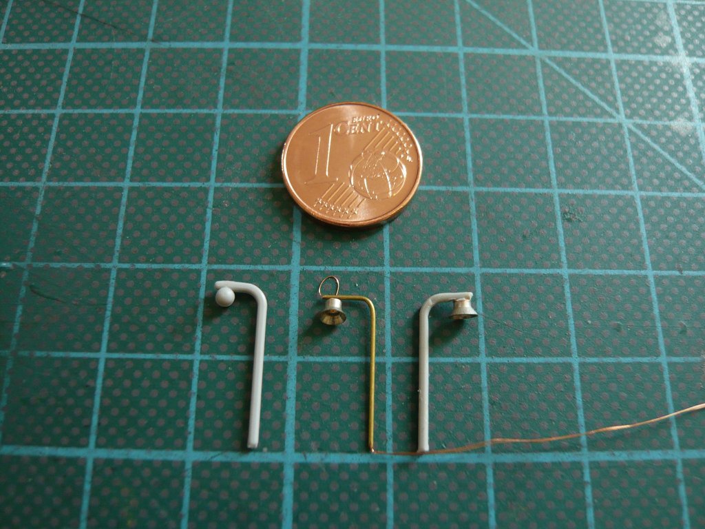 I don't want to blaspheme, but when I see the Revell arc lamp I inevitably have to think of the fairy tale of the "ugly duckling" ... And since we are dealing at the moment with dimensions, I would like to briefly refer to the help of my friend James, who I asked about the dimensions of the lamps and the diameter of the handrails on the pad, since at that time he was there day in and day out during building up Pad B. In this way I wanted to clarify whether the diameter of the MLP lamps with shade (Ø 2,8 mm, 1:160) is right and roughly corresponds to the RSS arc lamps estimated by using my STS-6 reference photos, especially since Ø 2,8 mm corresponds to a real diameter of the lampshades of approx. 450 mm, which seems pretty big to me ... In his detailed answer he started with the handrails, which, with a few exceptions, had a diameter of Ø 1,5" = 38 mm = 0,2 mm (1:160) on the entire pad.
__________________
Greetings from Germany Manfred Under construction: Launch Pad 39A with Challenger STS-6 (1:144) Last edited by spacerunner; 09-07-2020 at 05:57 PM.
|
|
#2249
09-07-2020, 05:03 PM
|
||||
|
||||
|
With reference to the data sheet Steel Pipe Specifications Schedule 40 he then referred to the fact that the Ø 1,5" refers to the Nominal Size (IPS), which corresponds to an outer diameter of Ø 1,9'' = 48 mm = 0,3 mm (1:160).
Furthermore, he also pointed out a small but fine difference in his photo, on which one can see in the red circle, that the stanchion of the lamp is attached to the handrail tube with two round steel brackets and has a slightly larger diameter, what I had already noticed before too. 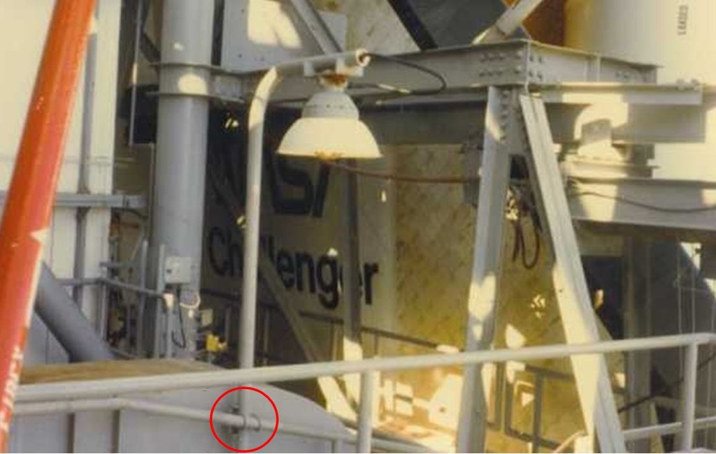 James assumes that, for reasons of stability, that for these upright standing handrails were used steel tubes with Ø 2"(Nominal Size) with an outer diameter of Ø 2,375" = 60,3 mm = 0,4 mm (1:160), which corresponds to a real diameter of at least approx. 60 mm, which is quite conceivable. And these two diameters, for the stanchions (Ø 0,4 mm) and for the handrails (Ø 0,3 mm) correspond well with those diameters estimated by me, wherewith the diameters of the MLP lampshades (Ø 2,8 mm) determined by me are also quite realistic. Now it was just a matter of determining the length of the bent end of the stanchion on which the lamp hangs, for which I used another photo of my padblower from its reworked and enhanced NSF thread Space Shuttle Launch Complex 39-B Construction Photos.  Source: James MacLaren, Pad B Sories (p. 3), 16streets.com Thereof results a length of approx. 5 mm (1:160), which corresponds with real approx. 80 cm, which seems quite plausible. In this photo one can also see that the stanchion of the lamp is a bit thicker than the tubes of the handrail. But since all RSS handrails in the Revell Kit have a diameter of Ø 0,8 mm and all FSS handrails even have Ø 1 mm and are therefore all oversized, it becomes clear once again that there will still be a lot of work to be done when I will substitute these handrails with PE handrails (Ship's railing (1:150) with Ø 0,3 mm made by ABER of Poland.  With this rather sobering outlook, I will leave it at that for today. Nevertheless, friends, nothing is impossible, Strength lies in calmness!
__________________
Greetings from Germany Manfred Under construction: Launch Pad 39A with Challenger STS-6 (1:144) Last edited by spacerunner; 09-08-2020 at 07:20 AM.
|
|
#2250
09-15-2020, 10:05 AM
|
||||
|
||||
|
Hello everybody,
now that the different lamp shapes on the Pad have been clarified and I know how to scratch them, I wanted more clarity about the wiring of the many LED lamp circles with the power supply of my planned Diorama (1/160, 160 cm x 90 cm). And my diorama could look something like this Mini-Diorama (1/700) by Tomytec, whose base plate is only 35 cm x 29 cm "big", but had a moon price of 682,30 €, but has been sold out since then.   Source: Andromeda24.de At first I had only planned a fixed arrangement/wiring of all pad structures/components in the starting position for the Dio, i.e. with the MLP with the Shuttle stack on the 6 Pedestals next to the tower, as well as with the Crawler on its way before it. The concept for the power supply for lighting the entire diorama was developed a few years ago in a close exchange with my Raumcon friend Arno (McPhönix), in which the Multi-Currentbank is the central component, which is designed for approx. 60 constant current circuits each with up to 8 LEDs, with which all lamp circuits of the Launch pad (FSS/RSS/Service facilities/spotlights) as well as the [color=blue ]MLP[/color] and the Crawler are powered. 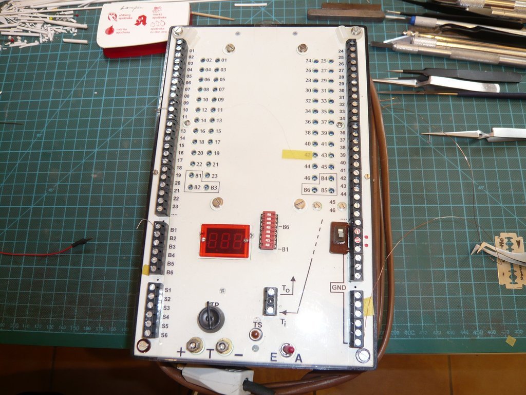 This original concept has in the meantime been revised and modified with regard to more location flexibility or Mobility of MLP and Crawler so that not only this one arrangement is possible with the MLP standing in front of the tower, but also during the MLP approach to the pad, like in this photo during the Challenger rollout (December 8th, 1982) in the fog. Source: forum.nasaspaceflight.com Likewise the cabling between the diorama and the power bank has also been modified so that it can be separated if necessary. 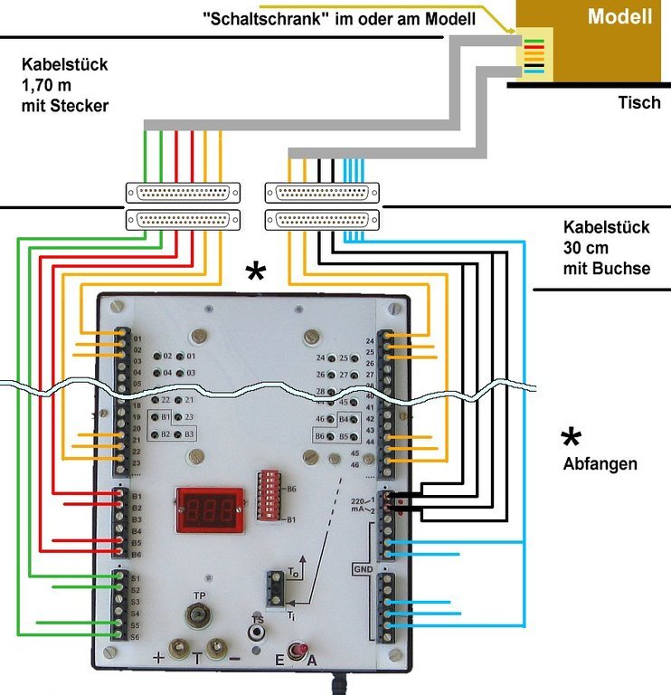 In this context, I initially had a detachable cable connection on the MLP via a small plug-in connector on the underbody next to the Pedestal 3, which I have now moved to the other side and planned for the Pedestal 6 besides the tower, since the whole cabling of the FSS/RSS is also planned on this side and all cables/wires can be led down together to the pad bottom. 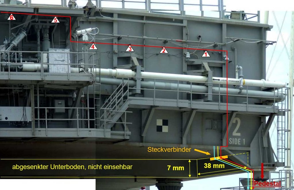 In order to be able to implement this mobile location concept, we have meanwhile also agreed to install our own power supply (three 9 V batteries) in the Crawler, on what also the MLP can be connected by means of a plug connection if it is in a pulled-out position on it. Consequently, a suitable location had to be found for an interface between the power bank and the pad cabling, which is shown in this drawing with the connection plate, 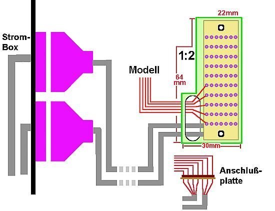 Source: McPhönix whereby NASA befriended us with the construction of the pad infrastructure with a small building, as will be shown later. In order to get a better overview of the local conditions on the Diorama as well as an idea of the size of the space available for the wiring of the pad assemblies, I picked out my former Dio draft, what for I've used an older one Google Maps image (2012) on which was seen the Launch Pad 39A in its original form with FSS/RSS, 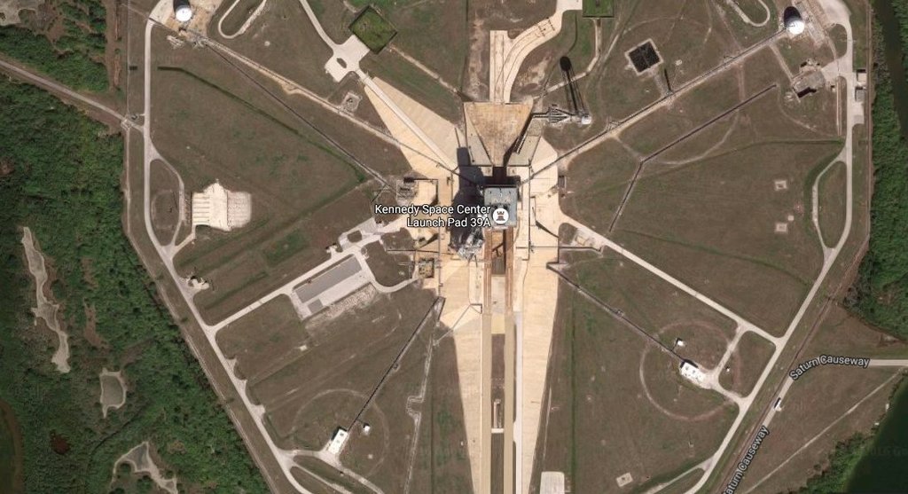 in which I have drawn the floor plan for the diorama in the Scale 1:160 (1600 mm x 900 mm) and marked the MLP and the crawler. 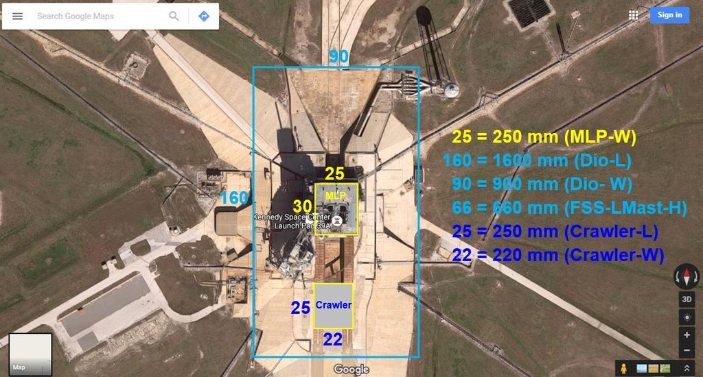 Then I've drawn the Dio to scale on paper and put on placeholders for the MLP and the crawler, for which I had to roll up the carpet in the study. And while I kept checking the dimensions on the PC in between, Gino had made himself comfortable at the end of the Flame Trench and began falling asleep ...  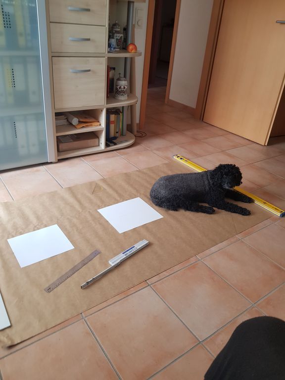 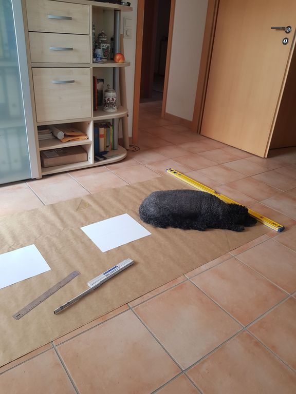 And since it was already late or early again, we've went to sleep together ...  And with that, good night ...
__________________
Greetings from Germany Manfred Under construction: Launch Pad 39A with Challenger STS-6 (1:144) Last edited by spacerunner; 09-15-2020 at 10:21 AM.
|
 |
|
|


 Linear Mode

