


|
|
|
#2641
 05-14-2022, 02:25 PM
|
||||
|
||||
|
And on the Back side (Aft Bulkhead) there are also four Vertical Transportation Support Plates, also made of Styrene (0,3 mm), which of course should not be missing.
 Then I took a closer look at the Spike, which contains the Upper Door Seal Control Panel,  which I had previously only imitated as a Dummy. which I had previously only imitated as a Dummy.  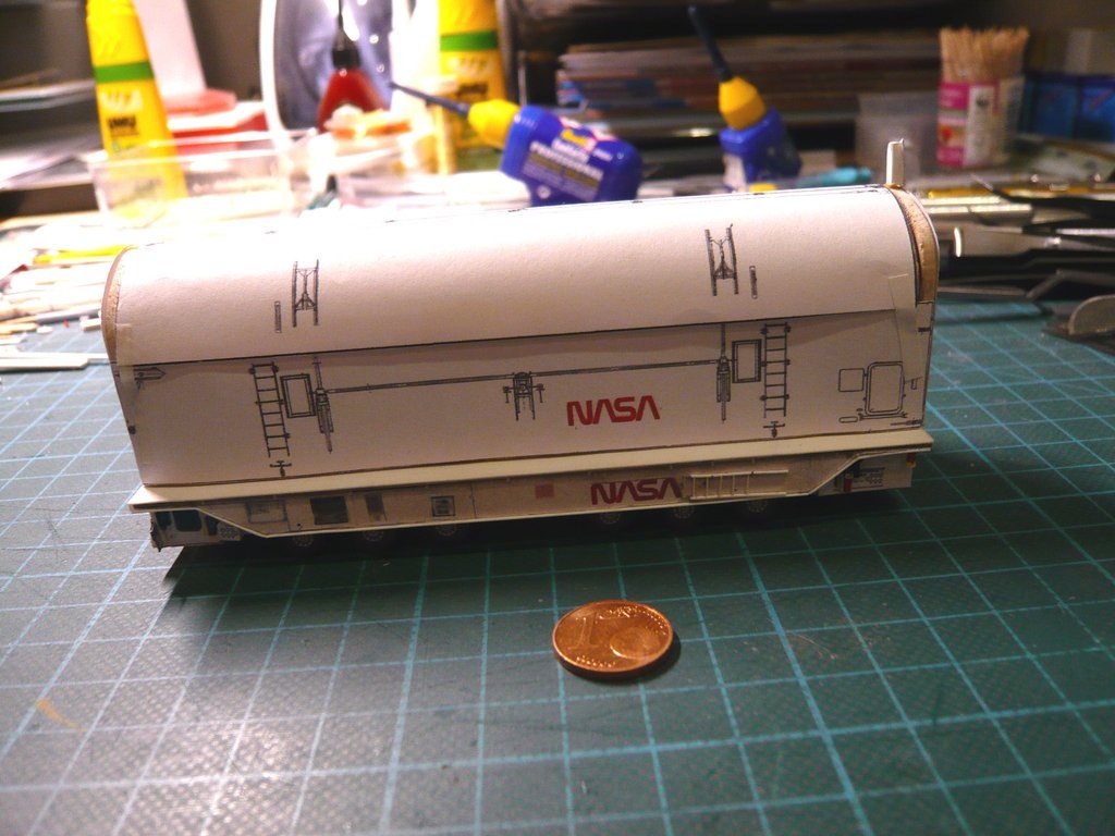 On closer inspection, however, one sees that this is not just a simple thorn, but that it is divided into two and only its rear part tapers out, which is closed with a little hatch, which has a handle in the middle and a small socket at the top right, things which should perhaps be scratchable.  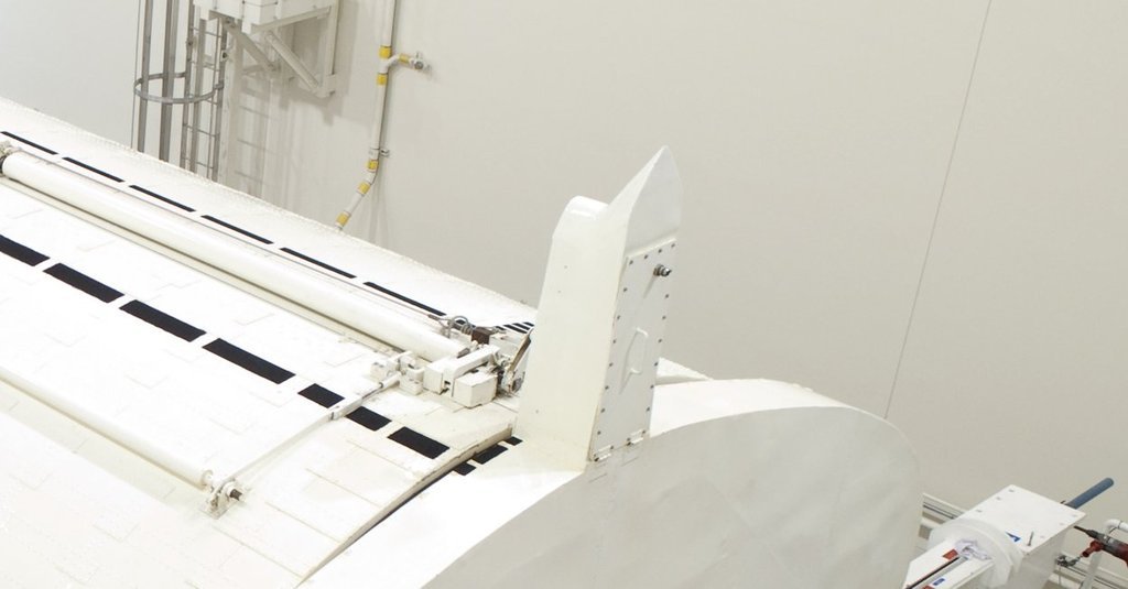 Source: NASA (STS-132) So I tried to spice up my Dummy (2 mm x 7 mm) a bit, 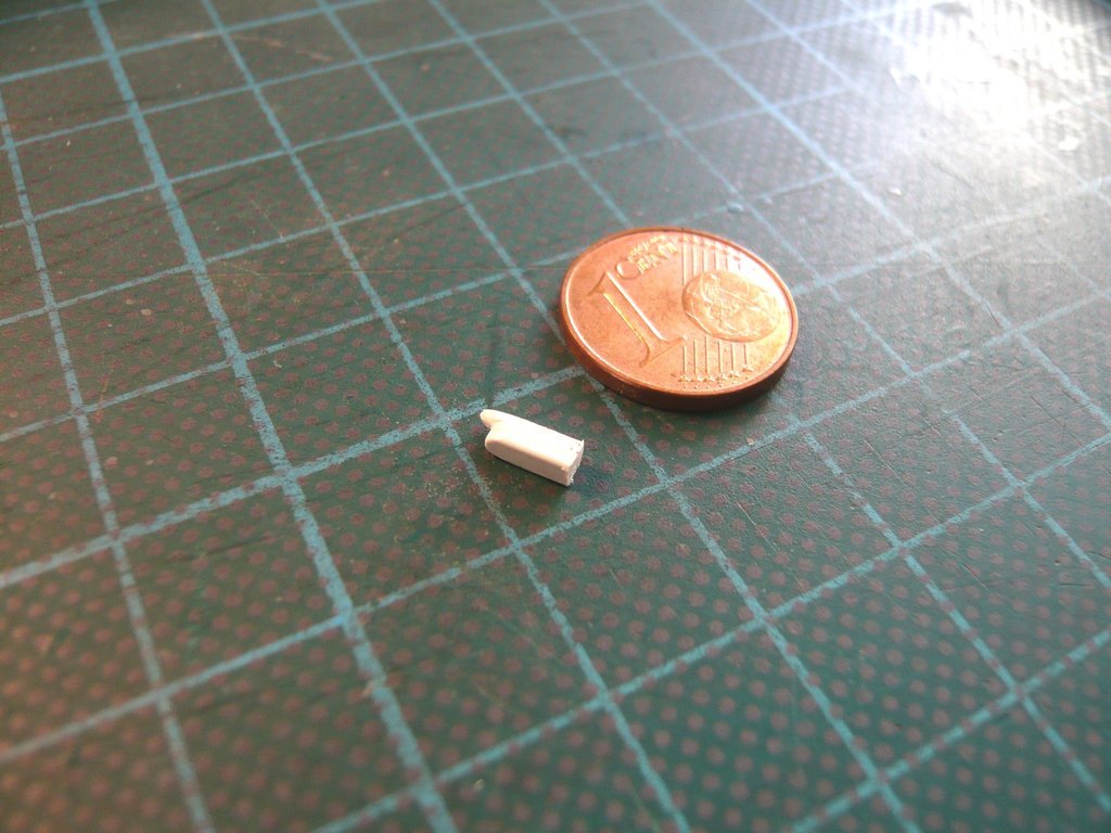  what I still didn't really like so much,  which is why I planned another Spike that I wanted to be a little more skilful with. which is why I planned another Spike that I wanted to be a little more skilful with.  
__________________
Greetings from Germany Manfred Under construction: Launch Pad 39A with Challenger STS-6 (1:144) 
|
|
#2642
05-15-2022, 03:30 PM
|
||||
|
||||
|
Hello everybody,
since such a small stub is difficult to handle and edit, in order to make the work with my 2nd Spike easier, I've used an Evergreen Strip (2 mm x 2 mm), on which I first removed half of the tip area and rounded off the front part. 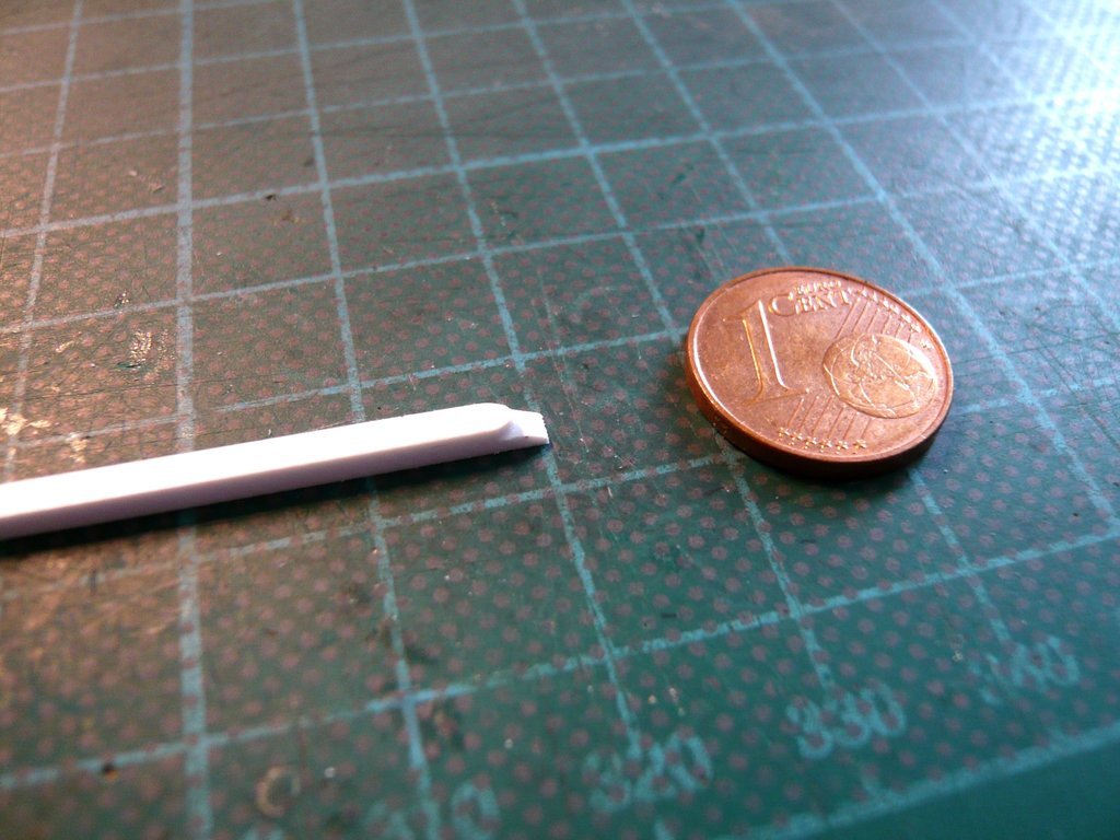 After that, I slowly worked the shape of the spike and carefully filed it bit by bit, slowly allowing the spike to take its final shape, which finally satisfied me.   The Spike was then shortened to the final, slightly longer length and sanded smoothly. 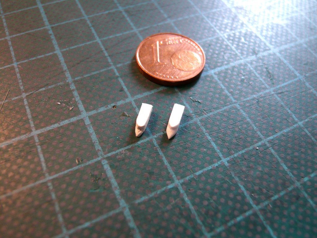 Here the other needed parts are to see, the Hatch made of Styrene (0,13 mm), as well as a Broom hair (Ø 0,15 mm ) for the handle, which is barely visible, and a German silver wire (Ø 0,25 mm) for the Connector. 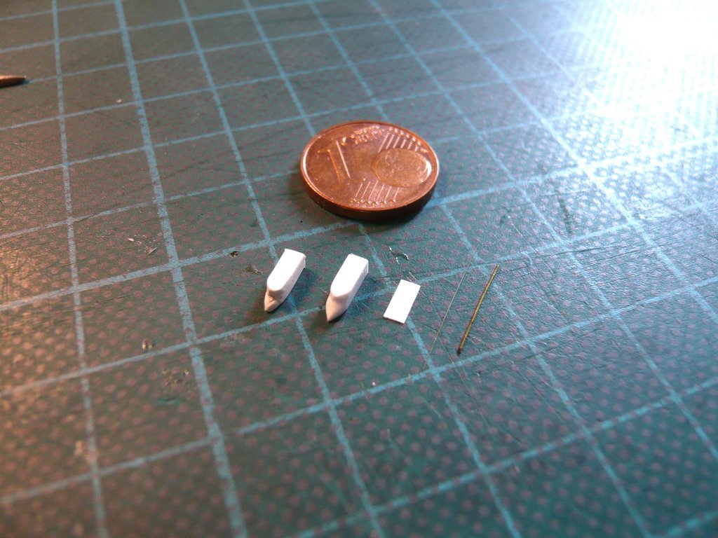 Then the holes (Ø 0,3 mm) for the handle and the connector were drilled and the handle was bent, which was a bit tricky, as it was only 1 mm long, or better short.  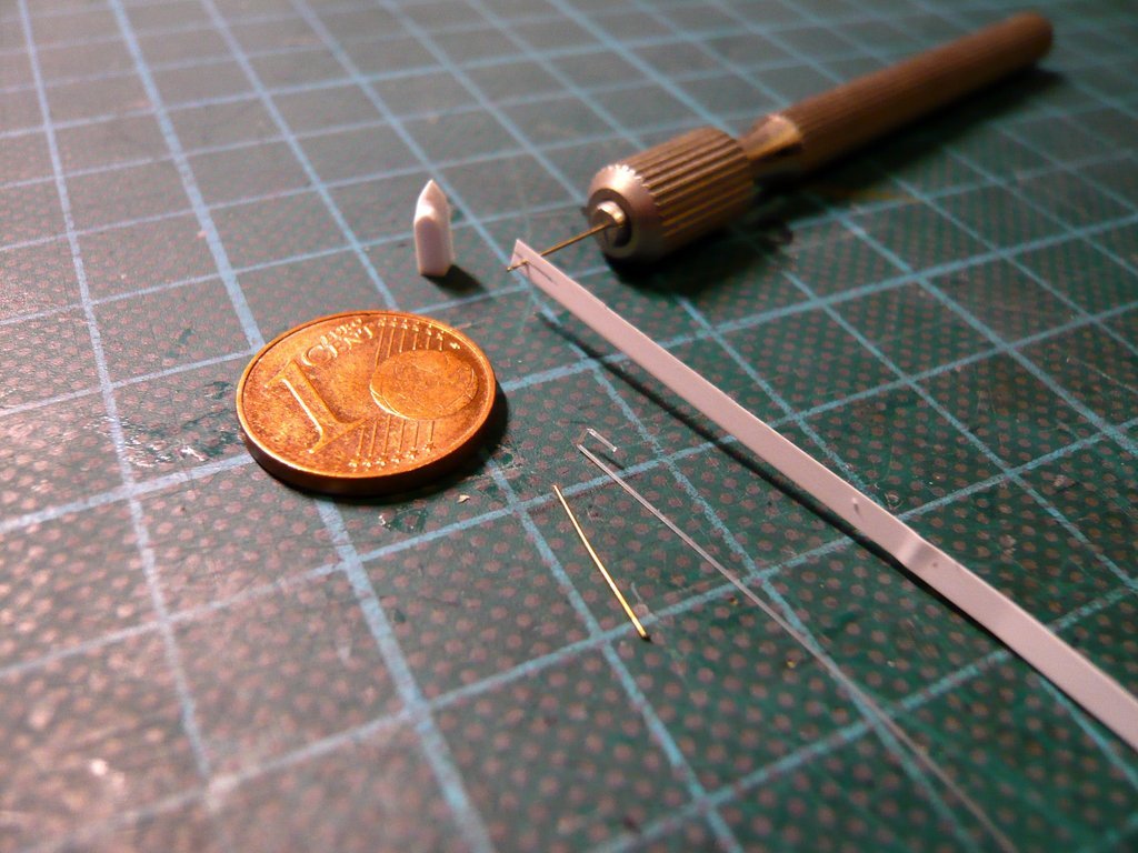 Then the hatch was glued to the Spike and the holes re-drilled to the required depth. 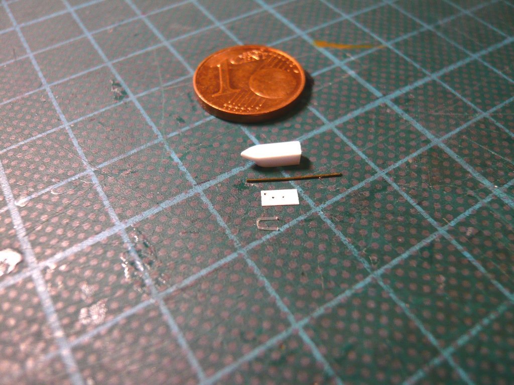 Gluing in the shortened handle and the short connector into the holes was quite a game of patience,  but it finally worked. but it finally worked.  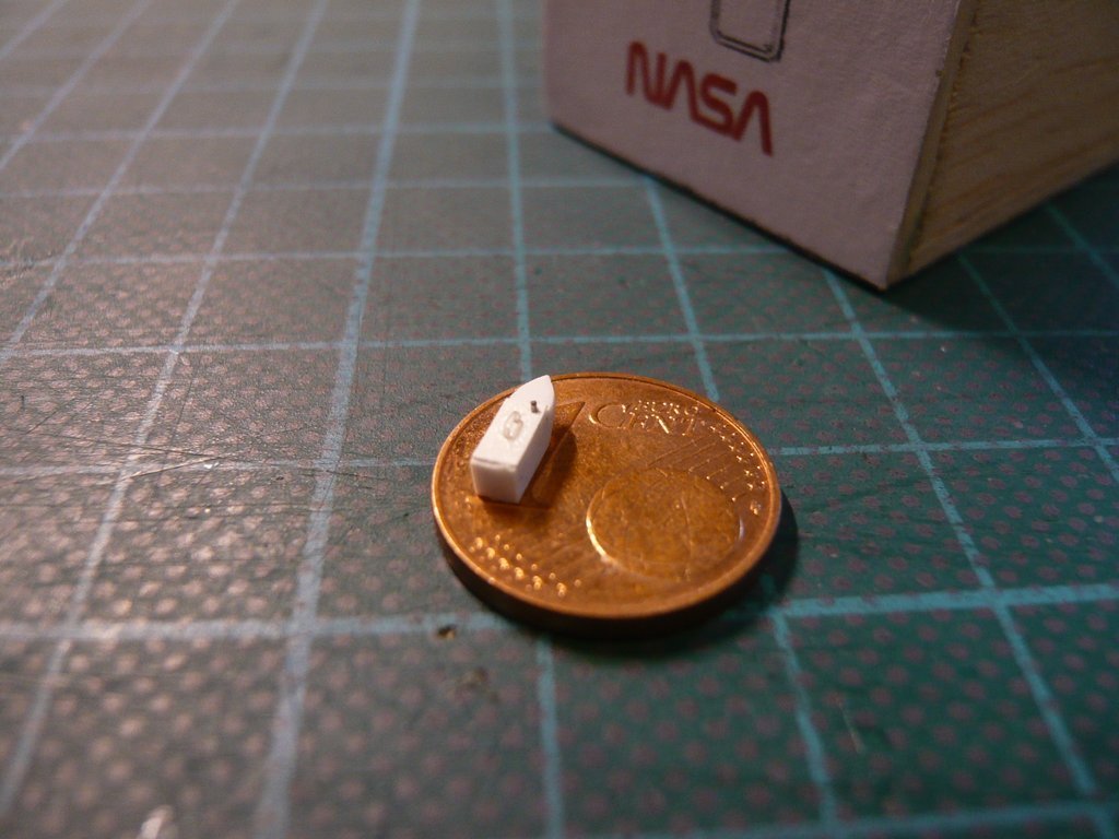 With this the finished Spike could actually be glued onto the Aft Bulkhead,  but wherewith I want to wait, until the Door covering and the Side walls are glued on.
__________________
Greetings from Germany Manfred Under construction: Launch Pad 39A with Challenger STS-6 (1:144)
|
|
#2643
05-19-2022, 12:13 PM
|
||||
|
||||
|
Hello everybody,
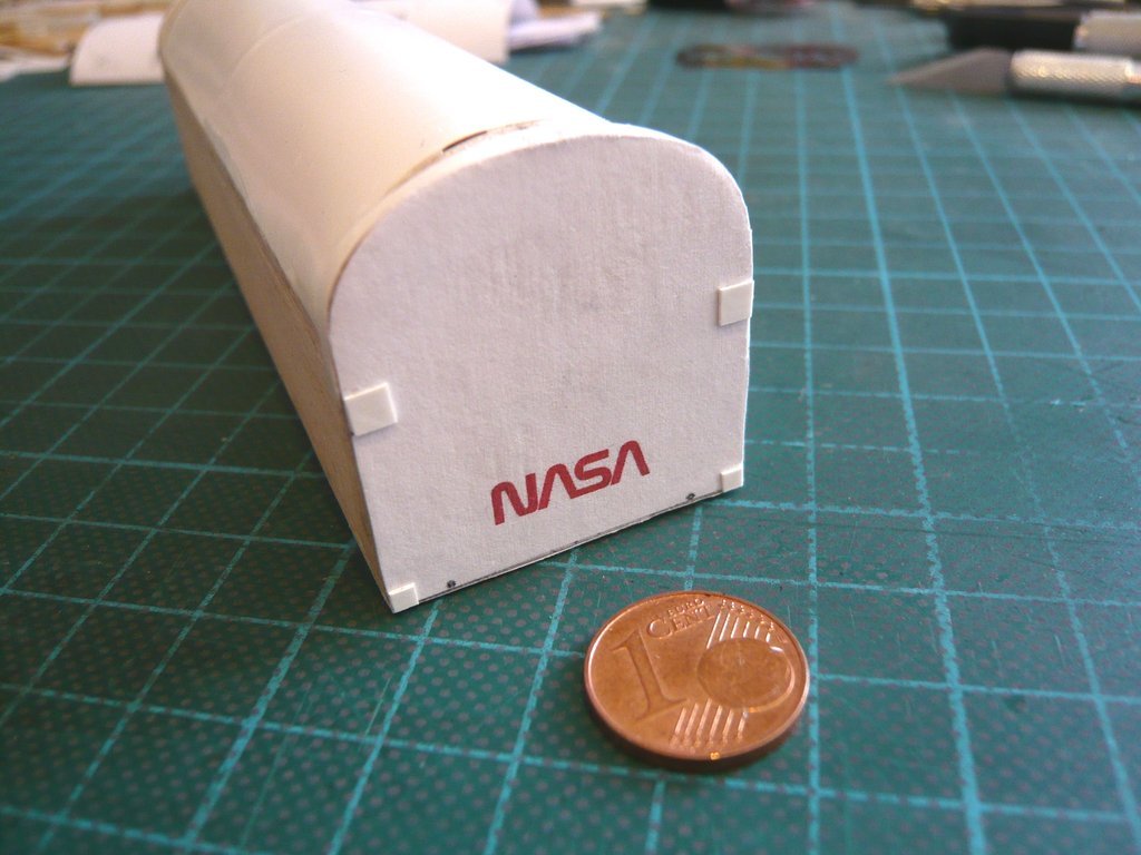
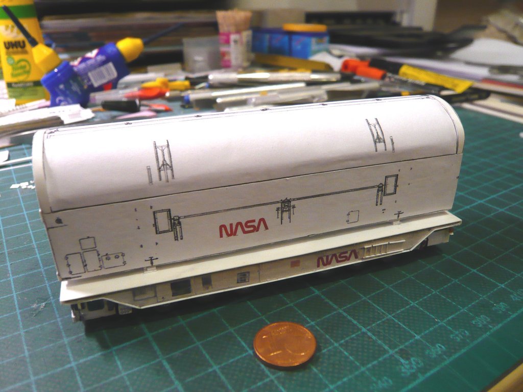
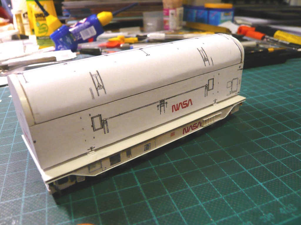
after I had made enough fittings, the final wallpapering of the Payload Bay Doorss and Side walls of the canister could now be done. According to the intended order, the door covering was next in line. After unrolling the previously rolled-up cover, its shape fitted the curve very well.  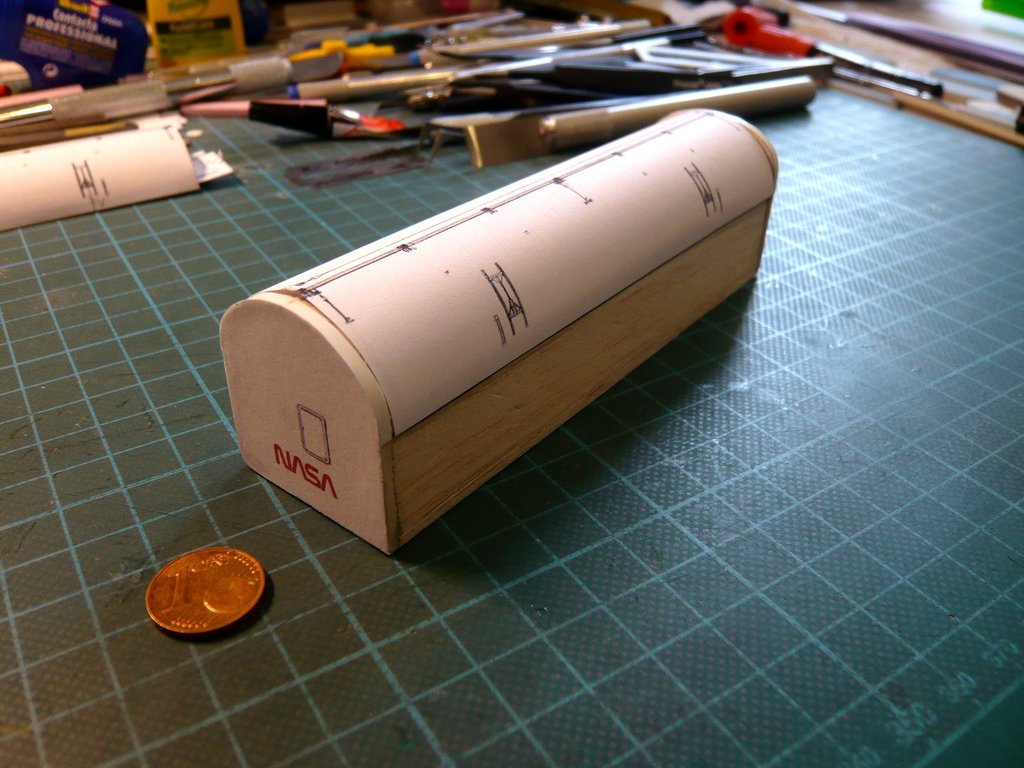 Then I have coated the upper edge of the side wall on the left side (Port side) as well as half of curves of both Support walls with UHU glue and glued the Port Side Door while carefully pressing on.  This was followed in the same way by the Starboard Side Door. Doing so I've noticed that while handling three of the Vertical Transportation Support Plates on the Aft Bulkhead had peeled off, but which were found and were glued together again. 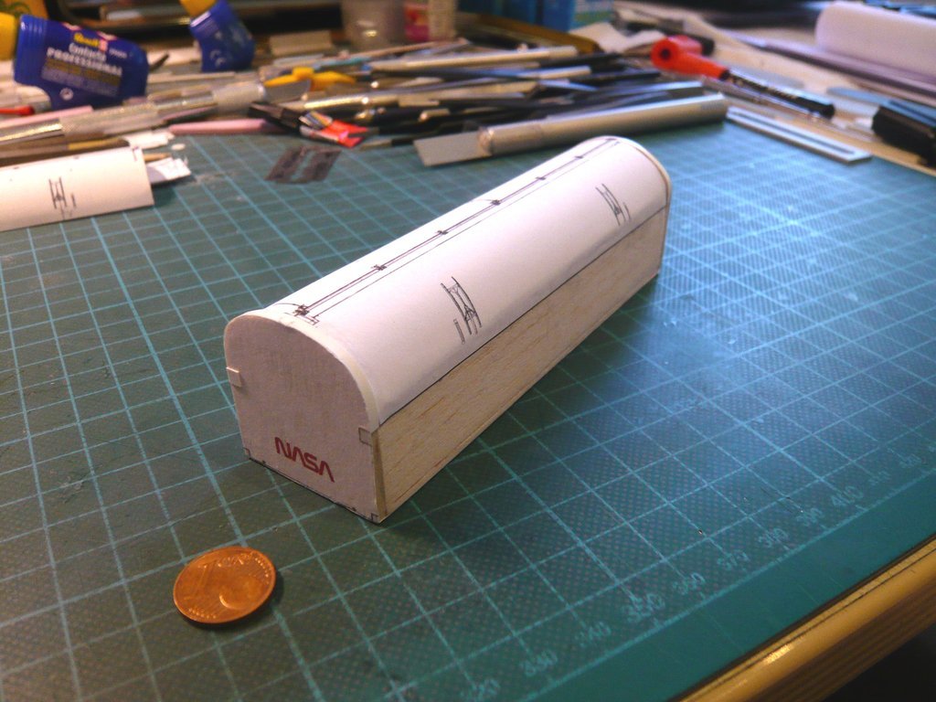 Then the Port side wall was wallpapered first,  and then the Starboard side wall in the same way. 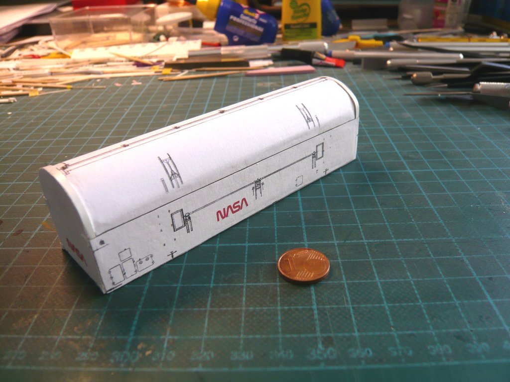 With that, the compulsory exercise was successfully completed, in the way I had imagined. Then there was the obligatory test fitting of the canister on the transporter with the temporarily attached Spike, what successfully passed my critical quality control. 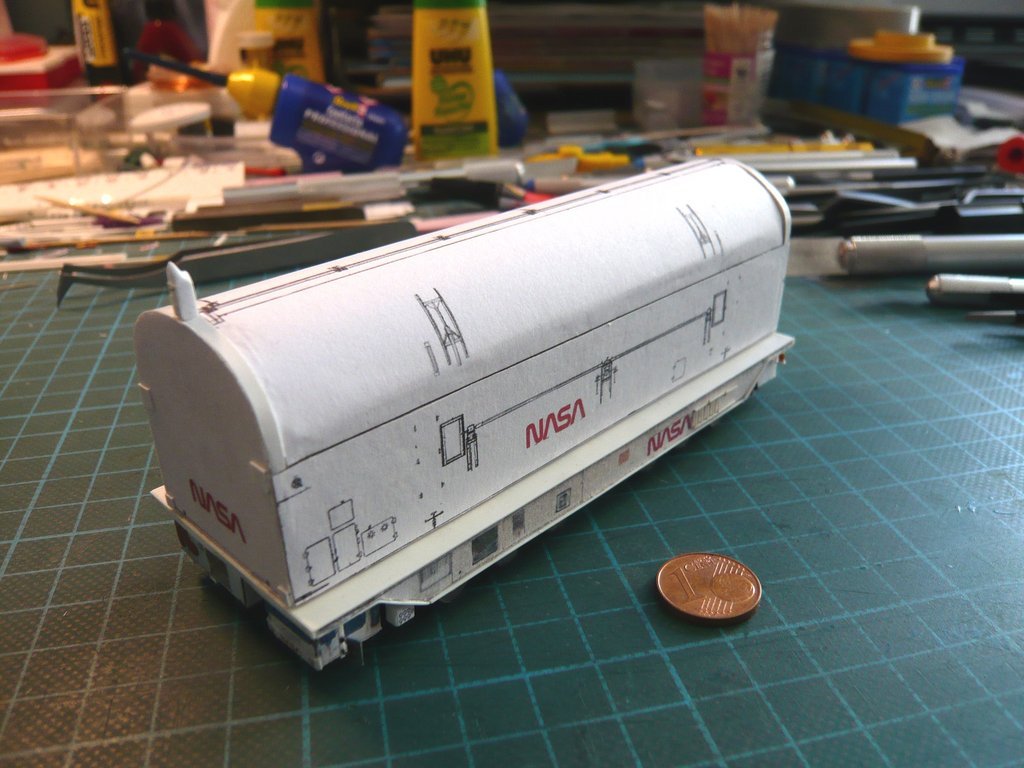  At this image you can see the transporter in the position, 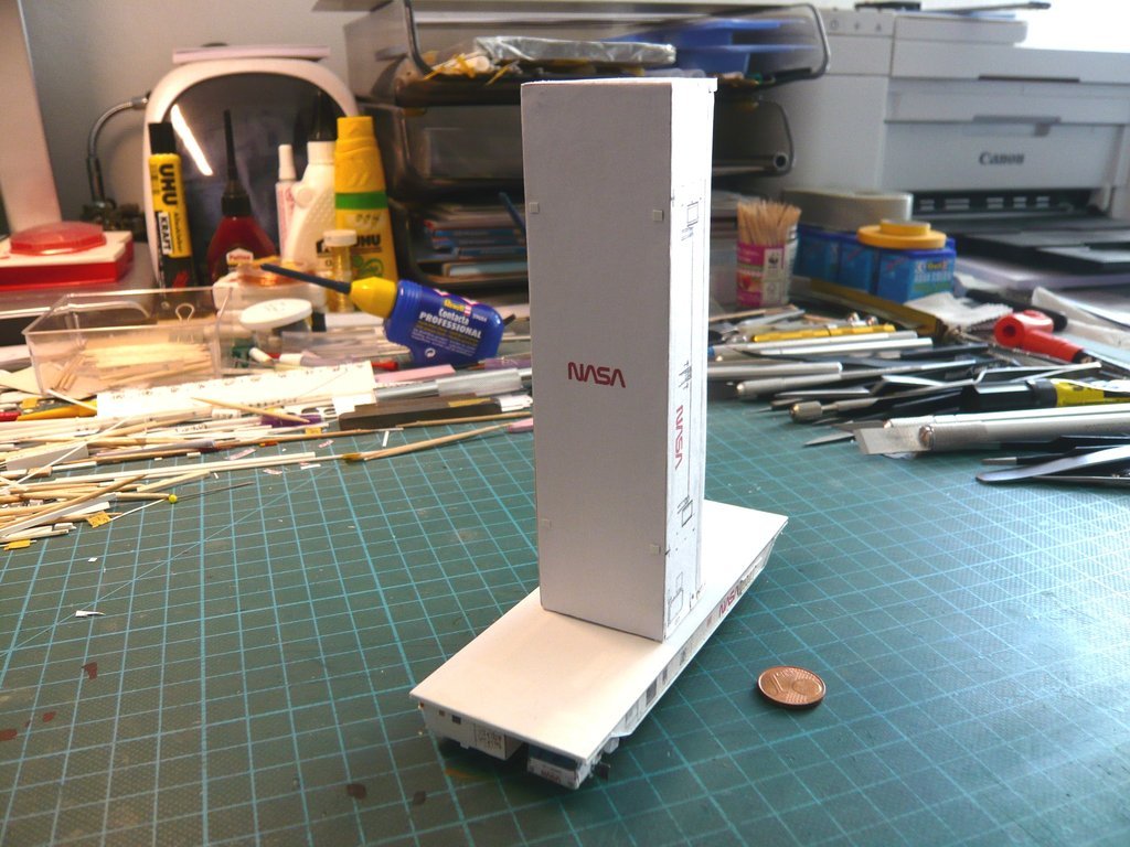 which he has when leaving the Vertical Processing Facility (VPF).  Source: retrospaceimages.com (STS-6) And in this position, the transporter drives the canister to the Launch pad, 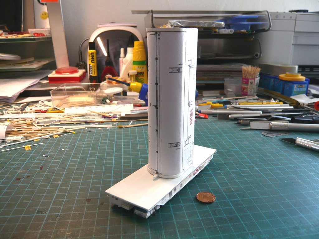 as was to be seen in this image already. 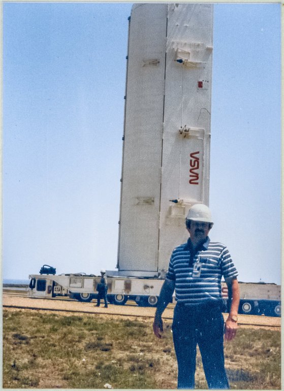 Source: 16streets.com/MacLaren After this compulsory exercise, the freestyle exercise can now follow, in which I will first turn to the Locking mechanism of the Payload Bay Doors, which I have already briefly described, whose linkage system can be seen in this photo of the STS-132.  Source: NASA (STS-132) But, as always, I first have to determine the dimensions of the individual parts in order to be able to scratch them.
__________________
Greetings from Germany Manfred Under construction: Launch Pad 39A with Challenger STS-6 (1:144)
|
|
#2644
05-20-2022, 05:57 PM
|
||||
|
||||
|
Hello everybody,
in the meantime, a friend on ARC Forums pointed out to me that there is more clearance between the canister and the transporter than on my model.  Source: ARC Forums (Jesper) His notice is absolutely justified and brings me to some other missing details, which are to be observed with both the Canister and the Transporter. The canister ist resting on the four Vertical Transportation Support Plates, which are also on the Transporter,  Source: NASA (STS-132) as I have now seen in retrospect and therefore have still to be added there.  Source: NASA But even more important are these four punched Vertical Transportation Tie-down Lug Plates, which engage fork-shaped Hold-down Clevises on the transporter deck, which are connected to the canister with large steel pins, and serve as anchor points for securing the canister in the vertical transport position. Then I've checked still more Hi-Res-photos and determined the distance between the canister and the transporter deck, which is approx. 1mm, which would look like this on my model. 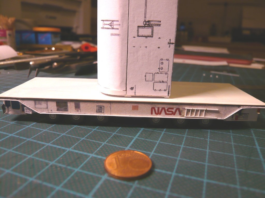 Therefore I will attach the missing Transport plates and also the horizontal and vertical Hold-down Clevises to the canister and Hold-down devices to the transporter, so that then everything complies with the safety regulations. Then I've also found out that these Hold-down Clevises were not permanently attached to the transporter, depending on the type of transport, but could also be dismantled, which can be seen in this image for the horizontal PLC Transport, when the vertical hold downs were not required.  Source: NASA (STS-135) Learned something new again!
__________________
Greetings from Germany Manfred Under construction: Launch Pad 39A with Challenger STS-6 (1:144) Last edited by spacerunner; 05-21-2022 at 07:34 AM.
|
|
#2645
05-21-2022, 07:31 AM
|
||||
|
||||
|
Hello everybody,
now I can think about how to scratch the Payload Bay Door Latch System. The door latch mechanism can be actuated from either end of the door by a Torque tube that runs the length of the door, which contains seven Door latches. Source: NASA (STS-132) As one can see in this image, there are seven Locking pawls on the tube which, when closed, lock both doors.  Source: NASA (STS-135) In a first step I've determined some dimensions for it.  Source: NASA (STS-132) Now I can look around for some suitable plastic profiles.
__________________
Greetings from Germany Manfred Under construction: Launch Pad 39A with Challenger STS-6 (1:144) Last edited by spacerunner; 05-21-2022 at 09:18 AM.
|
|
#2646
05-27-2022, 05:44 AM
|
||||
|
||||
|
Hello everybody,
well, as is so often the case, the devil is in the details and therefore first once more back to the Transportation Support Plates. And since the Payload Canister also rests on special Support Plates during horizontal transport too, now I have been dealing with these plates more closely and have tried to get me smart about the replica. This photo again shows an overview of the different Transportation Support Plates that were mounted on the transporters for either the horizontal or vertical Transportation Mode.  Source: NASA Since this is one of the two KAMAG transporters delivered in 2000, both types of Support plates were mounted at the time, which was not normally the case. At least the Hold-down Clevises, here to see on the vertical transport plates (red circles), were only mounted during the vertical transport of the canisters to the Launch Pad, but which were dismantled during horizontal transport in and between the assembly and processing facilities in the KSC, as could be seen in one of the last posts. It can already be seen from this image that these transportation support plates had a special structure and were not just simple support plates for the canister. So I first looked at the corresponding photos to see details for the scratch construction. Among other things, I came across this photo of the canister at the STS-135, on which one can already clearly see the outline of the horizontal support plates in plan view, which I got started with.  Source: NASA (STS-135) According to this, two Border strips are arranged on a Base plate around the support of the Canister transportation plates, which are probably used for roughly fixing the canister when lowering onto the transporter.  With this I was able to determine part of the dimensions of the components, which is always very time-consuming, but is simply necessary for the replica and requires a reliable Reference dimension (blue) ...  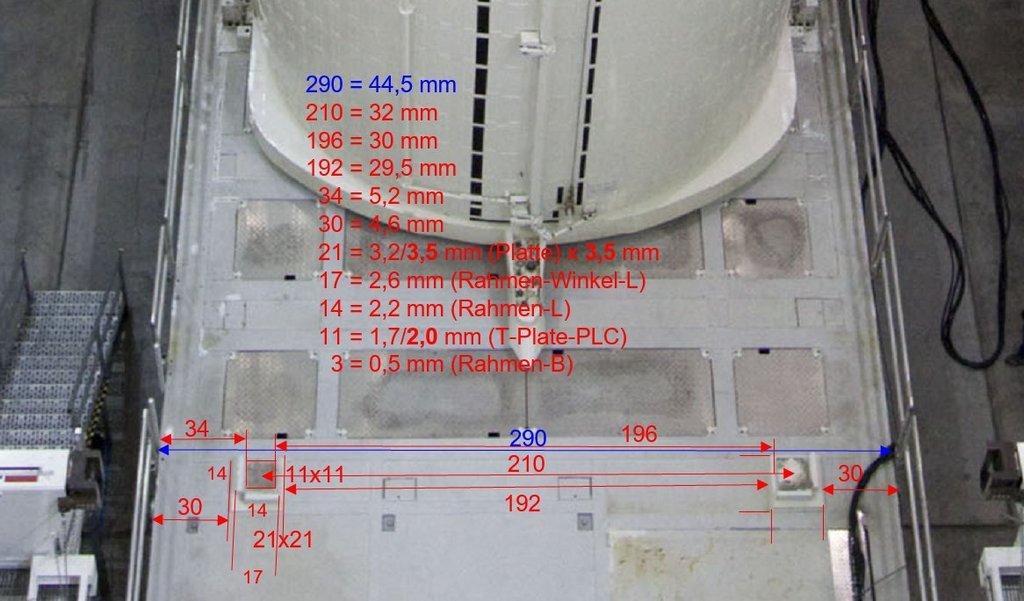 I was able to get further information about the arrangement of the components from this image,  Source: NASA in which one can see in the zoom that there is a separate Support plate for the canister on the base plate, which completes the arrangement of the parts, after which the dimensions of the parts could be determined and the plates could be scratched. o do this, I first had to reproducible cut off all the individual parts, but what is impossible without a defined stop, as can be seen here for the Base plates (0,3 mm x 3,5 mm x 3,5 mm). 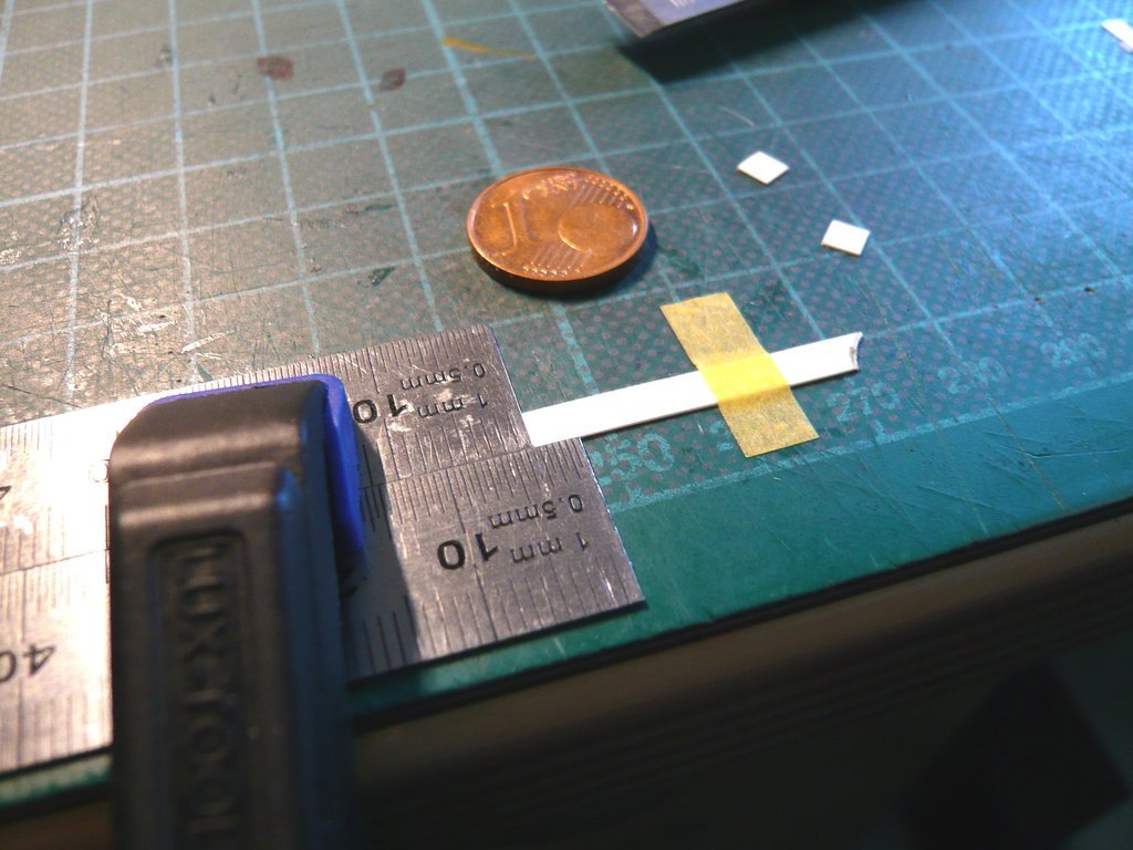 Next to it are the Border strips (0,5 mm x 0,75 mm x 2,5 mm) and the Transportation support plates (0,5 mm x 2 mm x 2 mm ), to be glued to the bottom of the canister. Of course, to glue the parts onto the base plate, it had to be fixed, for which I've stuck a strip of tape with the adhesive side up on the mat, 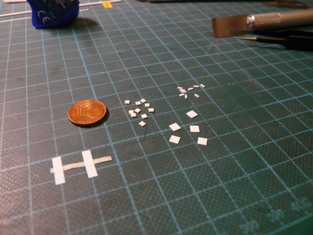 what has provided adequate hold and has worked, as can be seen from both sides on the finished plate, which I am happy with so far. 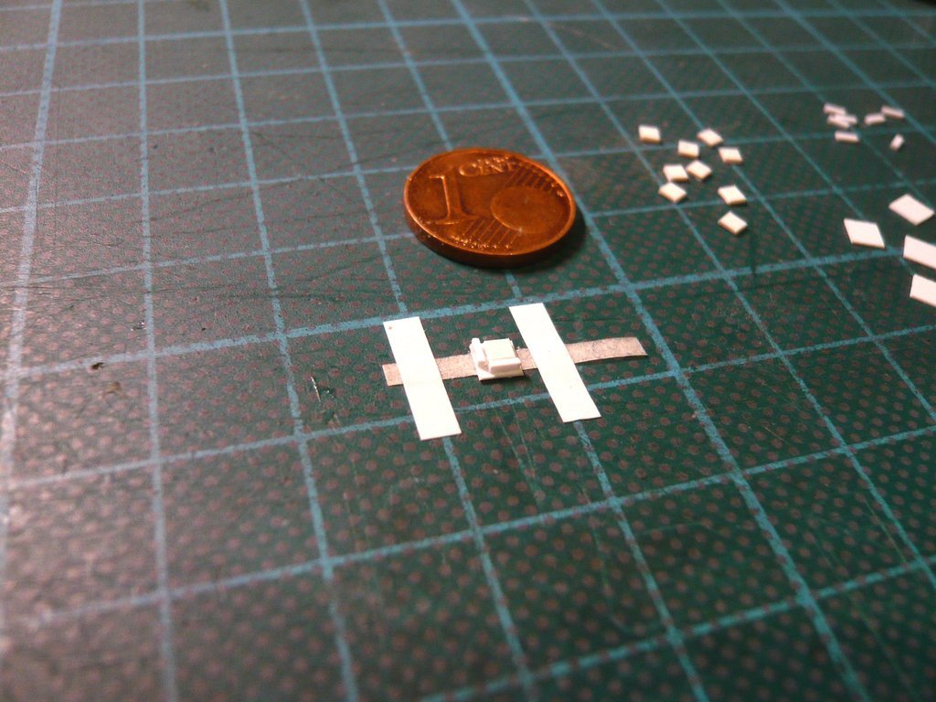 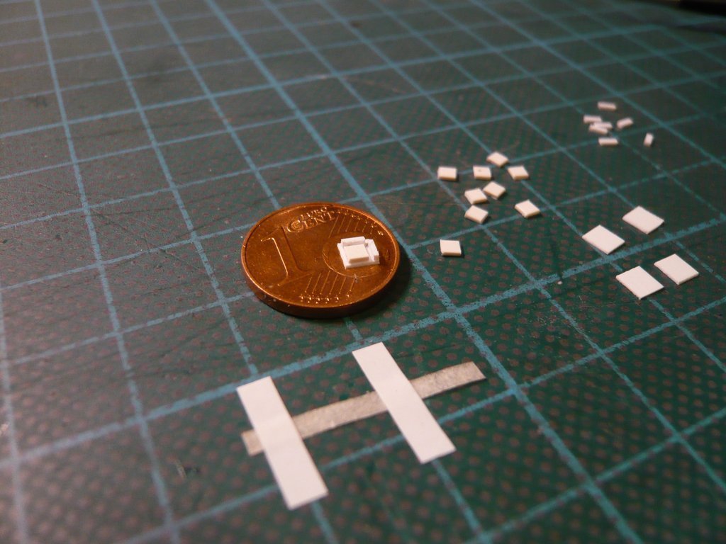 The difficulty in dimensioning the parts was that their heights had to be dimensioned in such a way that the underside of the canister must not rest on the border strips, but a certain overhang must be guaranteed, which is actually the case. To do this, I placed a canister support plate onto the inner transporter support plate as a test in the following image, which later creates the necessary overhang of the canister. 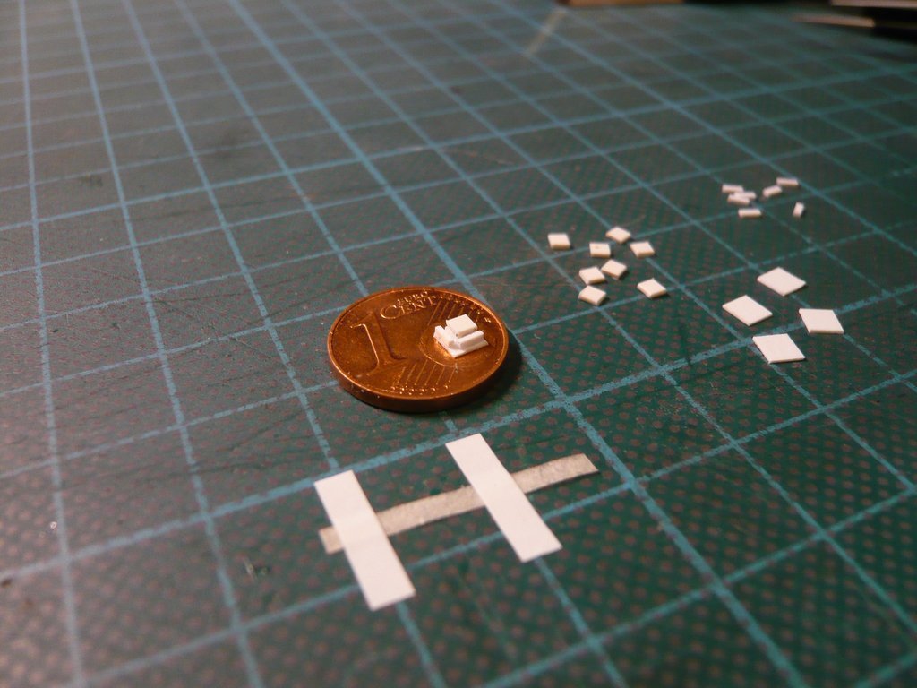 Now I can scratch the other three horizontal Support plates in the same way and in peace. Although these are only small, inconspicuous parts that will hardly be visible later under the canister, but should not be missing.
__________________
Greetings from Germany Manfred Under construction: Launch Pad 39A with Challenger STS-6 (1:144)
|
|
#2647
05-28-2022, 02:33 AM
|
||||
|
||||
|
Hello everybody,
so, get to work then!  With keeping the first succeeded Transportation Plate in sight, the other three went comparatively easily. 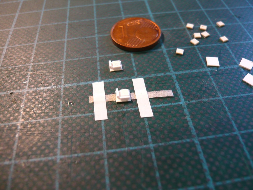 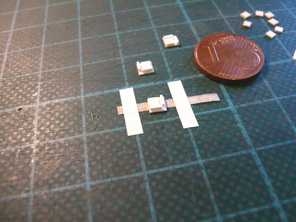 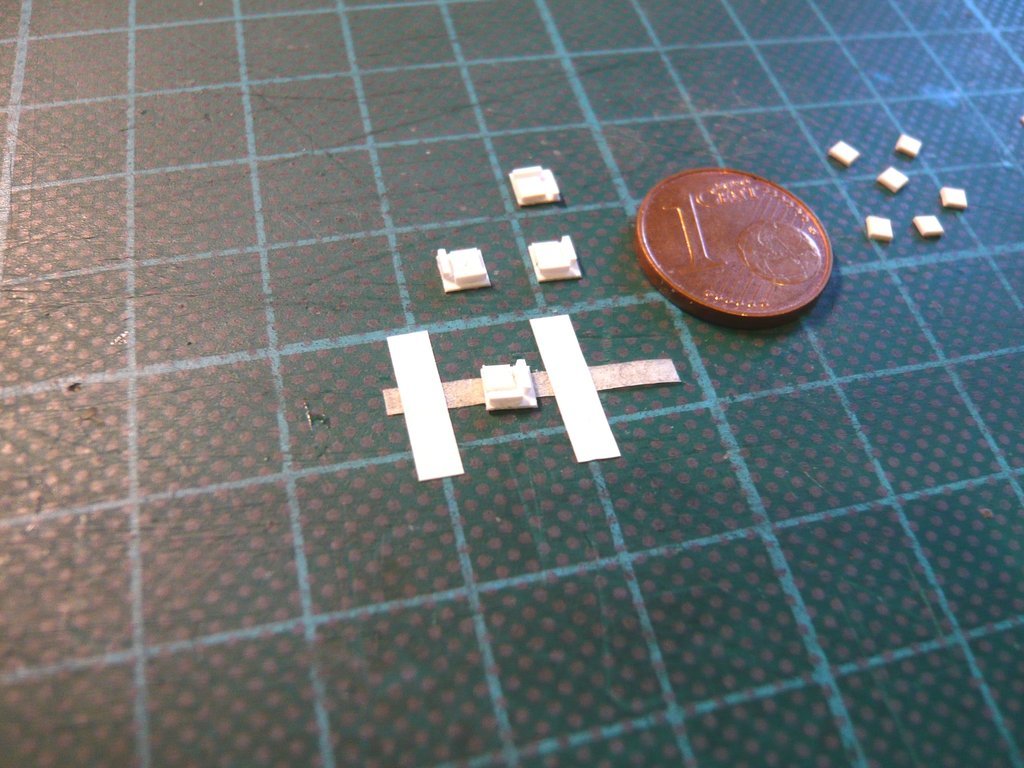 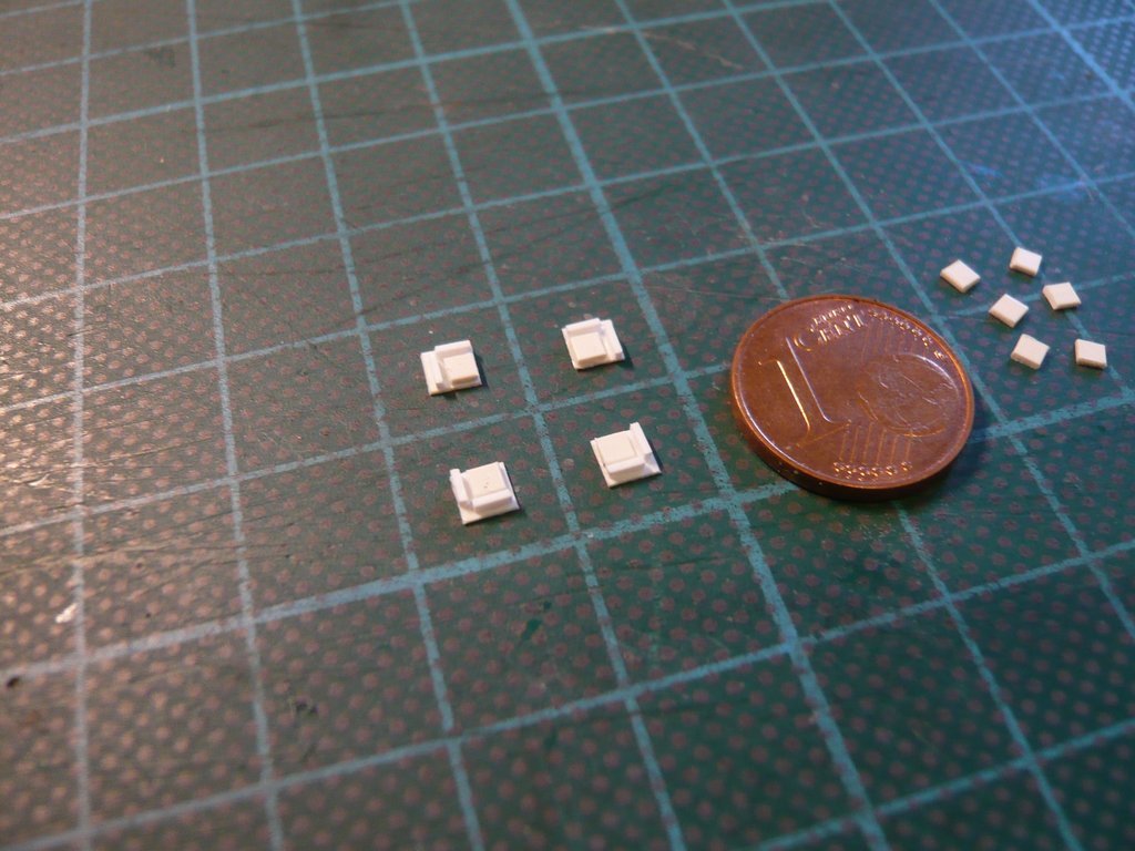 A first test fitting of these Horizontal Transportation Plates on the transporter looks unspectacular, but good, 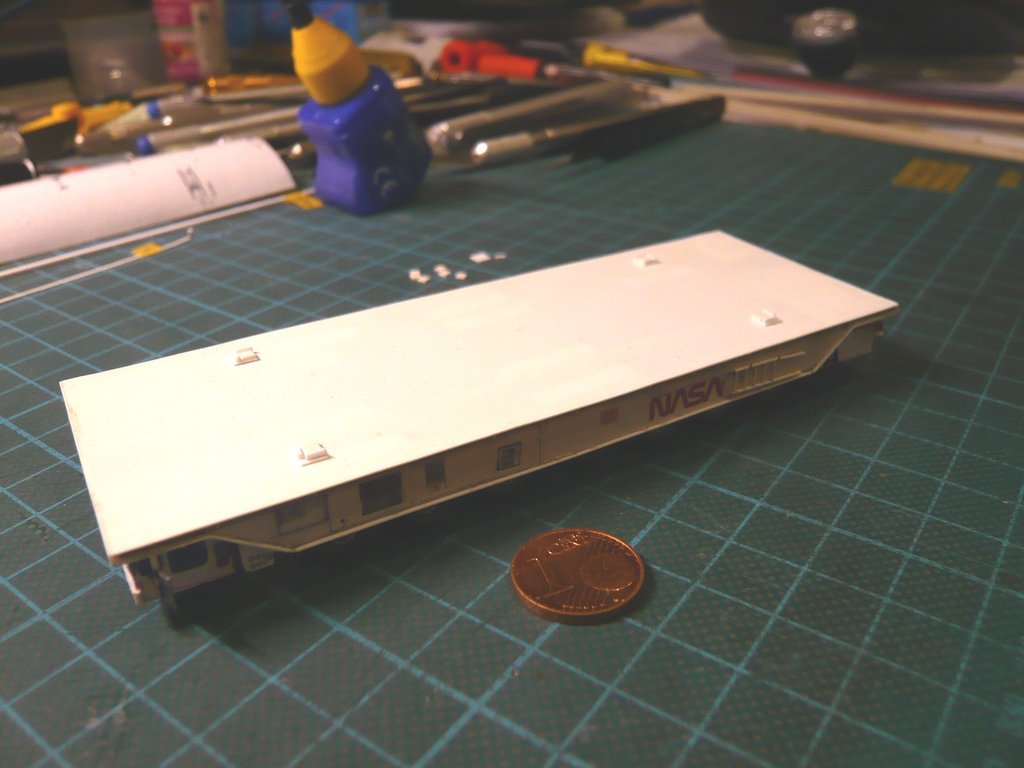 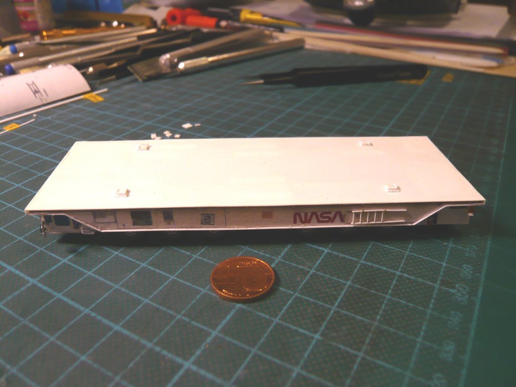 but now has to be compared with the canister with regard to the exact positions, since these plates must be below the Horizontal Transportation Tie-down Lug Plates, which are located directly below the ladders.  Source: NASA (STS-135) On this image one can see the Tie-downs underneath the ladders more clearly.  Source: NASA (STS-135) These would be the places on the model, which is why I have to measure them precisely so that everything fits together. 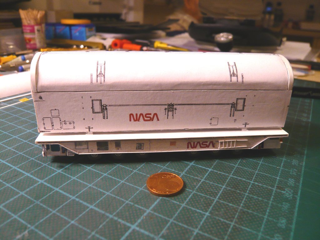 So much for today.
__________________
Greetings from Germany Manfred Under construction: Launch Pad 39A with Challenger STS-6 (1:144)
|
|
#2648
06-01-2022, 04:31 PM
|
||||
|
||||
|
Hello everybody,
and thus to the exciting question of how I can best glue these Transportion Plates for the horizontal transport, both on the Transporter as well as on the Canister, what I had to think about beforehand. To do this, the question of the sensible order of the gluing had to be clarified first, so that in the end the positions of the plates on the transporter and on the canister bottom match and are in the right place.  Since the transportation plates of the Transporter must be directly below the Horizontal Transportation Tie-down Lug Plates of the Canister, which are located directly below the ladders, 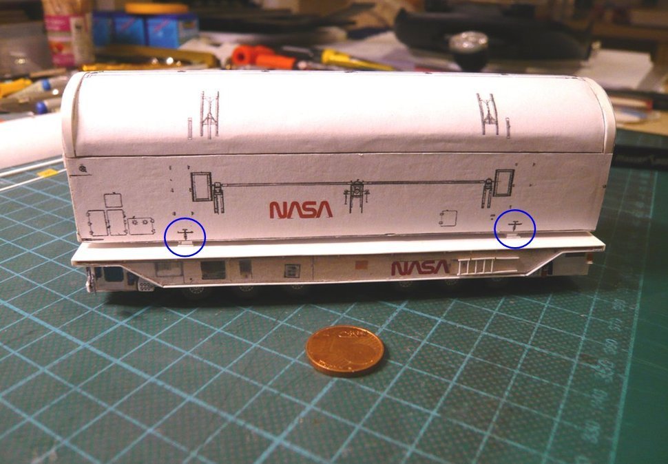 it became clear to me relatively quickly that first the plates on the transporter and then those on the canister bottom had to be glued. To do this, I first transferred the plate positions of the canister to a transparent printout of the Transporter platform, 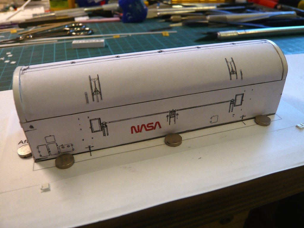 and have just laid out the plates temporarily, 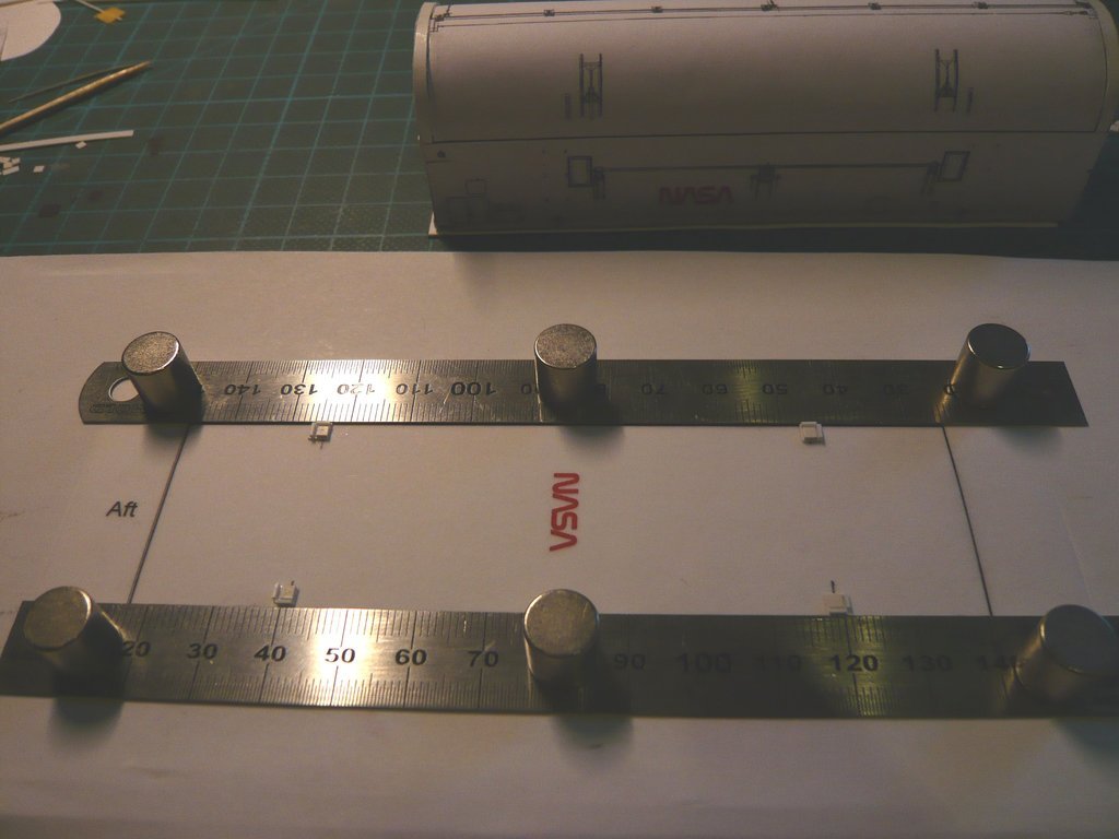 to be able to measure their distances for later gluing on the transporter. When I was handling with the plates, I was suddenly horrified to find that there were only three plates left and one was missing.  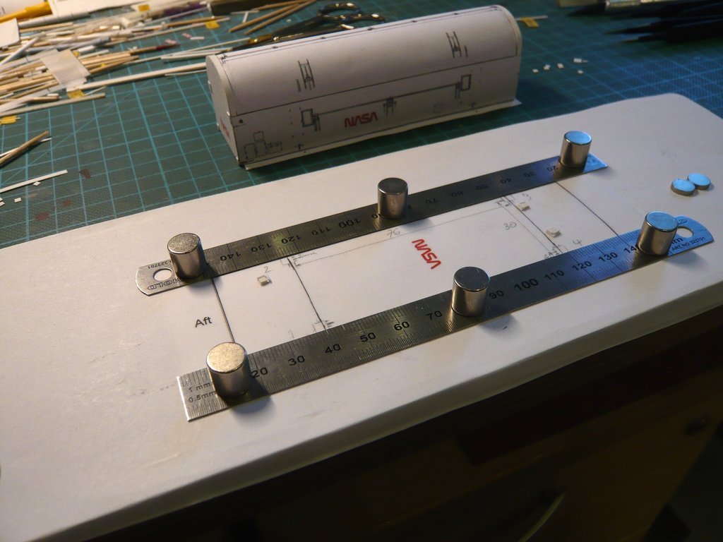 Since the fourth plate could not be found on the table, I got up cautiously and actually saw it lying on the floor intact, so I could continue with peace of mind.  When all four panels were finally glued to the transporter, I was able to catch my breath a little bit, 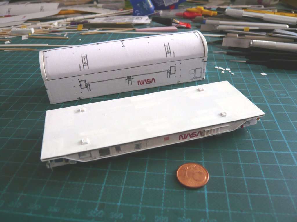 because the test fitting of the canister was okay so far. 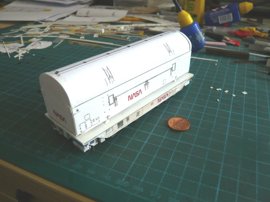 But that was only half the battle, because now I had to do the even more difficult part of the exercise, namely to transfer the positions of these plates exactly to the bottom of the canister for gluing them, which I still have to think about carefully.
__________________
Greetings from Germany Manfred Under construction: Launch Pad 39A with Challenger STS-6 (1:144)
|
|
#2649
06-02-2022, 04:33 PM
|
||||
|
||||
|
Hello everybody,
since any measuring and marking of the positions of the small Transportation Plates (2 mm x 2 mm) on the Bottom of the Canister would be far too imprecise and, on top of that, too uncertain I've come up with a solution that may seem a bit cumbersome, but it should work.  A prerequisite for the success of this delicate action is a stable holding of the transporter, which should not move, as it is about minimal distances. To do this, I supported the transporter in a special holder jig with Balsa blocks in such a way that the wheels hung in the air, so that they were not unnecessarily stressed during gluing, and the transporter was fixed on both sides with magnets to prevent it from slipping. 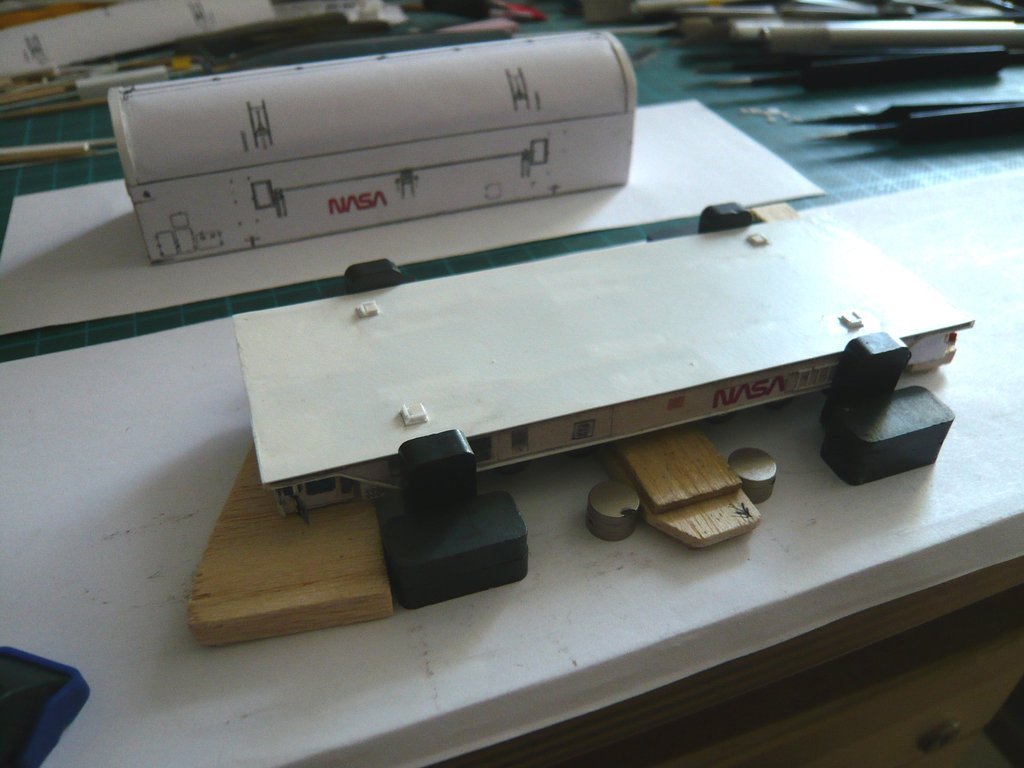 Furthermore, I used two Evergreen L Profiles (4,8 mm) as lateral stops, one side of which was cut out at both ends so that I would see the transportation plates glued on the transporter and would be be able to align the laid down canister accordingly. 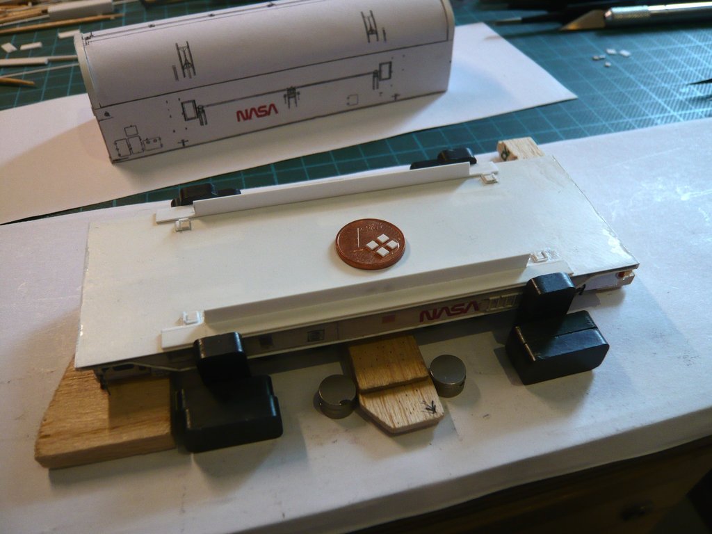 Then, in a first step, I wanted to carefully place the four transportation plates of the canister on the transporter's plates, 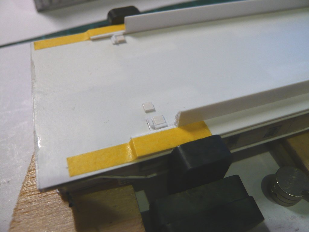 and align above them as precisely as possible.  But since no glue can be applied to these loose plates, I quickly changed my plans and glued the plates separately and one by one to the bottom of the canister, which was quite a tricky operation. But since no glue can be applied to these loose plates, I quickly changed my plans and glued the plates separately and one by one to the bottom of the canister, which was quite a tricky operation.  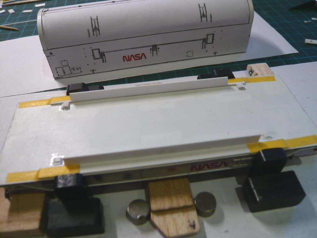 To do this, I took the plates off again before gluing them and dabbed them beside the transporter, one at a time with a tiny drop of UHU-CA, holding one corner of the plate with my fingernail. Then I carefully grabbed it with pointed tweezers and set it down even more carefully on the transporter's transportation plate and adjusted it slightly, which should become enough to drive me up the wall ...  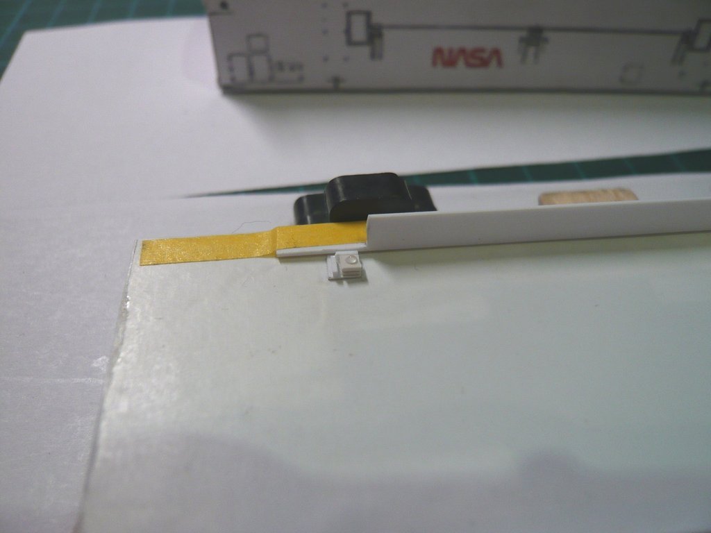 Then I've carefully and with a lot of feeling lowered the canister between the side stops onto the transporter plates, causing the glue-dabbed canister plate to stick to its bottom - if I was lucky, like for the first three plates.  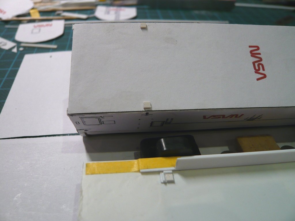 But it all went much too smoothly, because when picking up the fourth plate dabbed with glue, it got stuck on the tweezers and couldn't be set down, no matter how loudly I've cursed ...  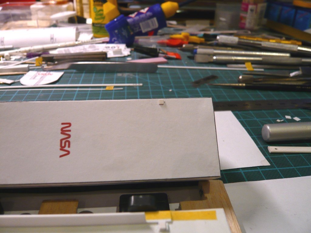 That's why this plate had to be cleaned again, dabbed again and set down onto the fourth Transporter plate, what luckily worked again. 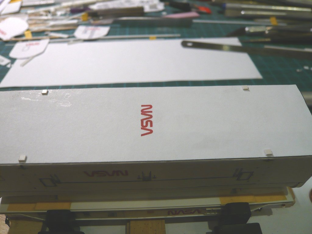
__________________
Greetings from Germany Manfred Under construction: Launch Pad 39A with Challenger STS-6 (1:144) Last edited by spacerunner; 06-02-2022 at 04:43 PM.
|
|
#2650
06-02-2022, 04:34 PM
|
||||
|
||||
|
With that, that difficult task was finally done, and the canister with its transportation plates fits nicely on those of the transporter's - Thank goodness!
   Now I can confidently turn to the Vertical Transportation Plates on the transporter, 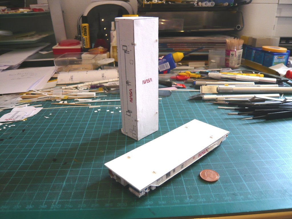 located in the middle of the transporter, 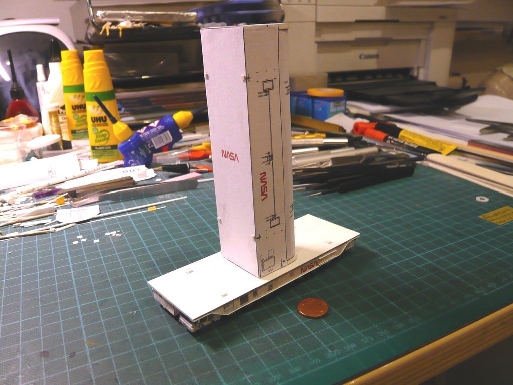 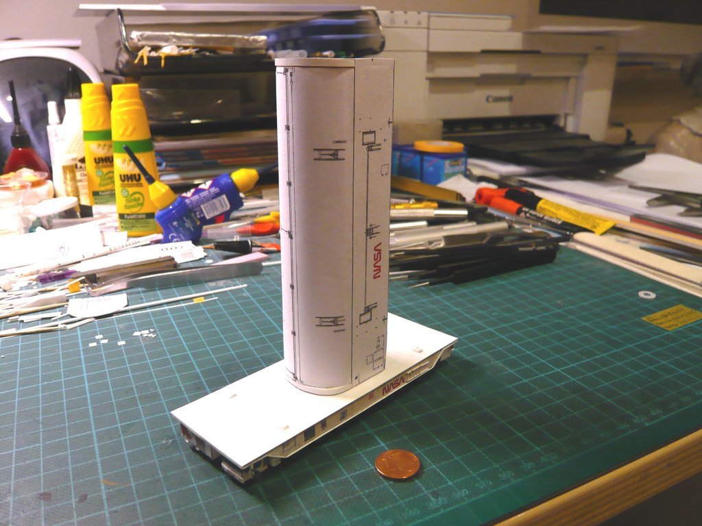 but have different sizes and structures as can be seen in this image.  Source: NASA (STS-135) On the one hand, this is due to the fact that they have to accommodate the differently sized transportation plates of the canister. On the other hand, they have recesses on the bottom for the Vertical Transportation Tie-down Lug Plates, which should make the scratch-building of these plates a bit more complicated and demanding.
__________________
Greetings from Germany Manfred Under construction: Launch Pad 39A with Challenger STS-6 (1:144)
|
 |
| Thread Tools | |
| Display Modes | |
|
|


 Linear Mode

