


|
|
|
#41
 08-09-2013, 10:23 AM
|
||||
|
||||
|
Thus, now I arrived finally to the last Access Platform AP 3 with the LOX & LH2 Valve Complex armatures. And there I try straight to pursue the props at the bottom of the platform since these are partly missing in the paper template.
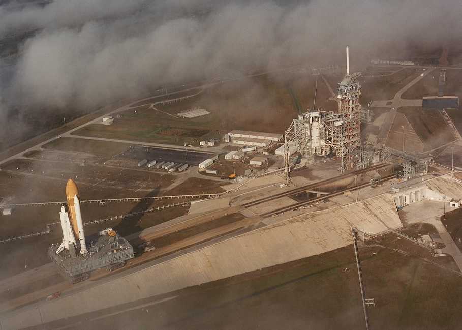
I have found a picture, in which one can see the profiles of the platform very well. 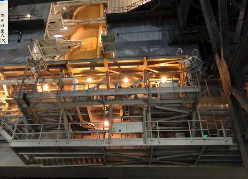 Source: NASA Here is again the paper template of the Access Platform AP 3 for memory, which look rather harmless from the structuring at first. As I know however meanwhile, that's not in reality at all like that, because already some props are partly missing, and even one is too much there. 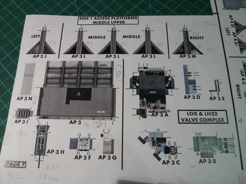 As one can see in the picture, this platform is to be carried by five struts illustrated above. That is not correct however, what becomes clear from the following NASA photo of the STS-121 in high resolution. There clearly the middle diagonal bracer is missing. I want to admit gladly that I recognized also only after repeated exact regarding and by comparison with further photographs.  Source: NASA And in the photo of my the latter post and further pictures one can recognize quite well the arrangement of the girders, I have tried now to detail all as well as possible which should become a bold venture however altogether.  Thus I installed first only the four girders and the front middle cross-beam from H-beam (1x1,5 mm). The lateral cross-beams and diagonal struts are made from rectangle profile (1,5x1 mm). Afterwards the two cross-beams lying above should actually come to. Since there are however still further longerons just, I wanted to only bond these, since appeared complicated as somewhat less to me. 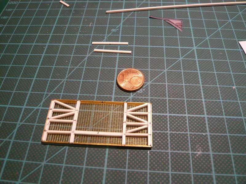 However, also like that the rest was a rather nerve-stretchin gaffair, which already cost me some time to this way, as one can see. And between the longerons just now still the tiny cross-beams must be glued.  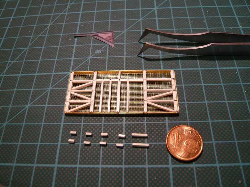 And here all the tiny cross-beams are now at its place, and still another few different props more, which was again a rather stressful action.  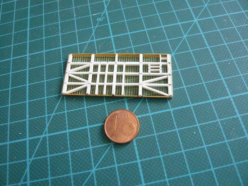 And then only the four bracers are missing in the end. And those are then altogether flabby 37 individual parts, inclusive brass frameworks and grating, if I counted correctly. Sometimes afterwards I am astonished at me, perhaps some one may also me doubt, but forget it ...  If the platform is finally finished then, I have however only times enough from props and gratings and make three crosses ...  Now followed still the diagonal bracers, which were glued together again with the help of the assembly block. 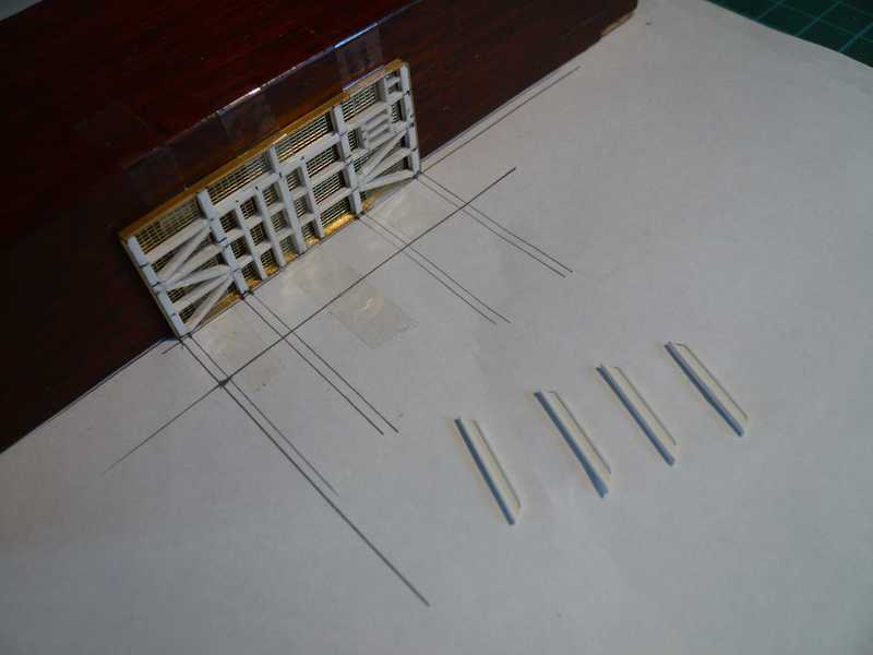 And that was relatively fast made. 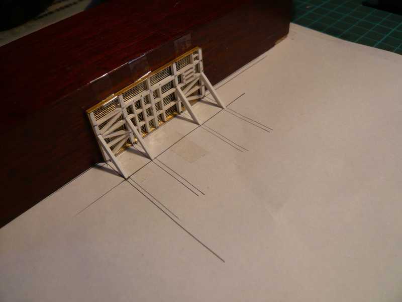 And with a small addition (?) as crowning conclusion - well, who from you has it discovered? - the Access Platform AP 3 was then finally finished, became yes also time.   And here again all four Access Platforms for the Side 1, from top to bottom AP 1 to AP 4, are in their whole splendor, from the bottom, 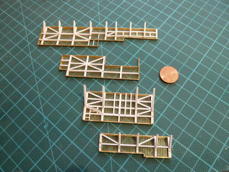 and in the end again from above. 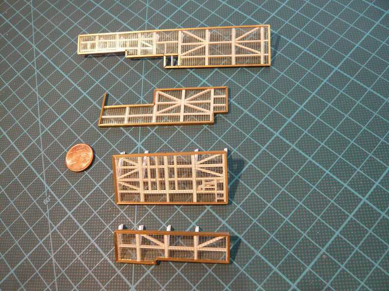 And thus now the platforms are finally completely to paint, and I make, as promised, + + +, I'm feeling slowly already as behind the bars ... 
__________________
Greetings from Germany Manfred Under construction: Launch Pad 39A with Challenger STS-6 (1:144) Last edited by spacerunner; 10-11-2016 at 06:47 AM. 
|
|
#42
08-10-2013, 12:38 AM
|
||||
|
||||
|
And to relaxation of the many lattices of the Access Platforms I planned now the MLP feet, the so-called Pedestals, on which the MLP with the shuttle stack stand beside the Launch Tower, if they were near dragged and set off by the Crawler.
Altogether there are six Pedestals, four at the MLP corners and two in the middle of the two sides (Side 2 and 4). 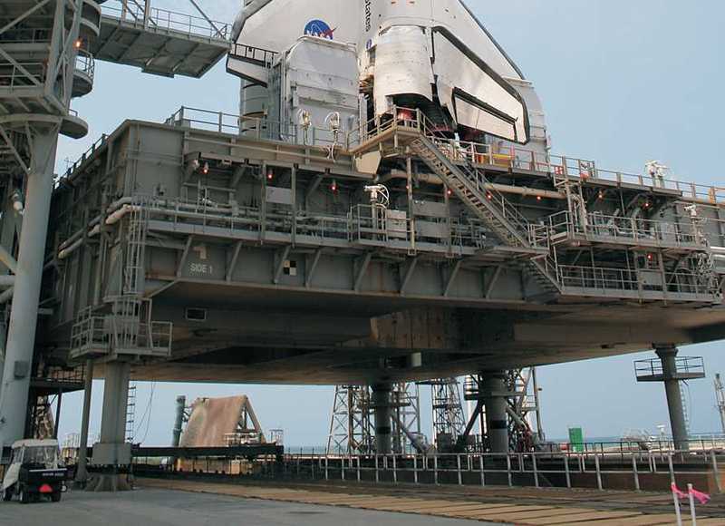 Source: NASA And that must naturally fit everything hair-exactly one above the other, before the MLP can be set off and bolted firmly. The platform must bear finally enormous forces during the shuttle start and stand still nevertheless. 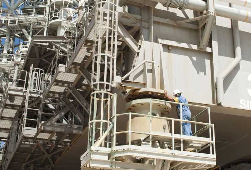 Source: NASA So that one can set the MLP off on the pedestals, one needs admission devices for the assembly, and those are the so-called Mount Mechanism Interface (MMI). In the picture on the left that is the middle MMI at Side 4, and right one can see a corner pedestal. The two corner pedestals at Side 1 look some more differently. 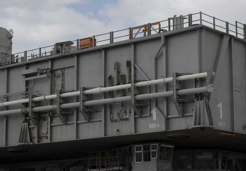 Source: NASA In the paper sheet the MMI parts look like these: 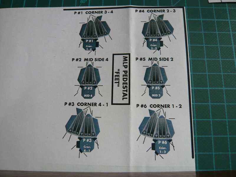 As one sees, are quite simple parts, and exactly the same they look then probably also at the MLP, as it were like small blocks. That would be now however nevertheless somewhat too simple for me, and therefore I had remembered the MLP Templates (P. 5-6) of AXM Paper Scale Model, which appears first still simpler, but built should them look surely more delicate. And thus or similarly it could also have arranged David Maier now, or about not? But unfortunately he did not make that however, like some other details also not. 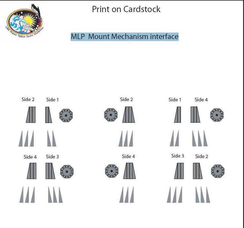 Source: AXM Paper Scale Model But for fun I built both variants to the comparison. First the baseplates come to the MLP bottom. In the kits template there only the pedestal numbers are printed on it. 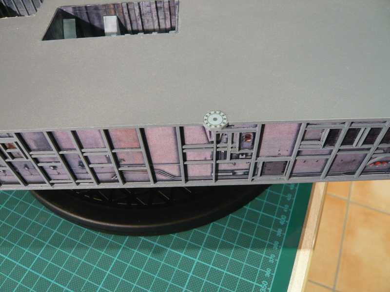 Afterwards I took first times cardboard and tried two samples, therefore looks and judges to best. 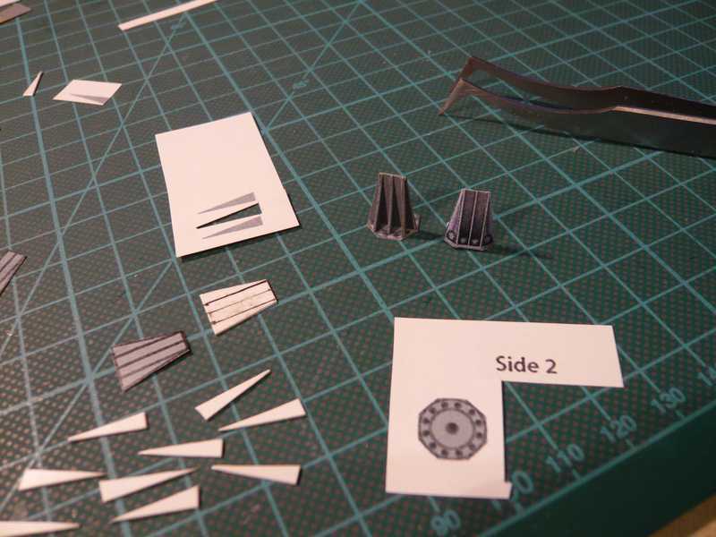 The variant (left), handmade after the AXM template, was finally painted with the brush. Besides already lie the parts made from Sheet, like the final version probably will are, inclusive Airbrush finish. Afterwards I attached for a test times both variants at the MLP, in order to have the direct comparison, as one can see here. The paper sheet variant would then still come naturally also on a small base plate and thus on the same height, that you may not disturb you. 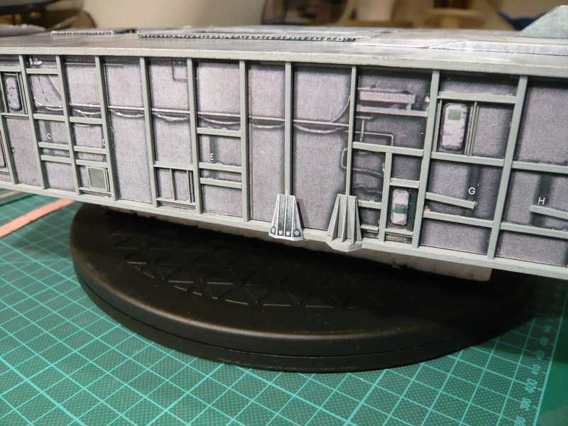 But just honestly, which pleases variant you better? 
__________________
Greetings from Germany Manfred Under construction: Launch Pad 39A with Challenger STS-6 (1:144)
|
|
#43
08-10-2013, 02:04 AM
|
||||
|
||||
|
Space Shuttle Launch Pad
Hi Manfred,
This Shuttle MLP build of yours takes my breath away! I think the one on the right looks best! I'll be glued to this thread... All the best, Bengt in Stockholm ")
|
|
#44
08-10-2013, 03:13 AM
|
||||
|
||||
|
Thanks Bengt for your nice words of appreciation!
 Yep, I fully agree with you and we have the same taste.  The AXM version suits me better and therefore I'll scratch build the MMIs like this, because the 3D design is obviously more realistic than the 2D design of the paper kit and it is also more accurate in size in my opinion.
__________________
Greetings from Germany Manfred Under construction: Launch Pad 39A with Challenger STS-6 (1:144) Last edited by spacerunner; 10-11-2016 at 06:51 AM.
|
|
#45
08-11-2013, 05:01 AM
|
||||
|
||||
|
At this pedestal detail a small general deficit of the actually great Paper kit of David Maier shows up.
All too small and above all still more complicated, spatial details cannot be represented of paper nevertheless so convincingly and can be converted still many more with difficulty. And in extreme cases completely tricky things can become then even easily unattractively, particularly regarded from the nearness. And that is probable the reason, why David Maier also sometimes abstain from it and some details are only suggested by textures. And last but not least everything is a question of expenditure, both for the CAD designer and for the modeler too. Therefore I want to build the pedestal MMIs from sheet after the AXM template, but with small changes to the corner interfaces, which are missing in both variants so far. As one can see in the next picture, the base plates of the corner interfaces exceed approximately to the half over the MLP corners. 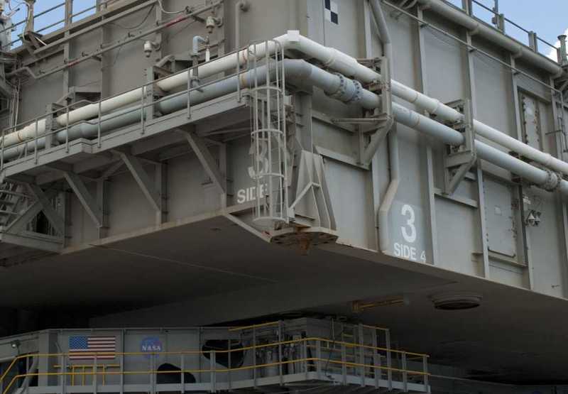 Source: NASA Therefore I have small angles of the supernatant corner interface made of sheet, which are glued together concisely with the corners of the MLP baseplate. Here one sees the individual parts for the corner MMI's, which was adapted on the basis of the AXM template still more to the original. 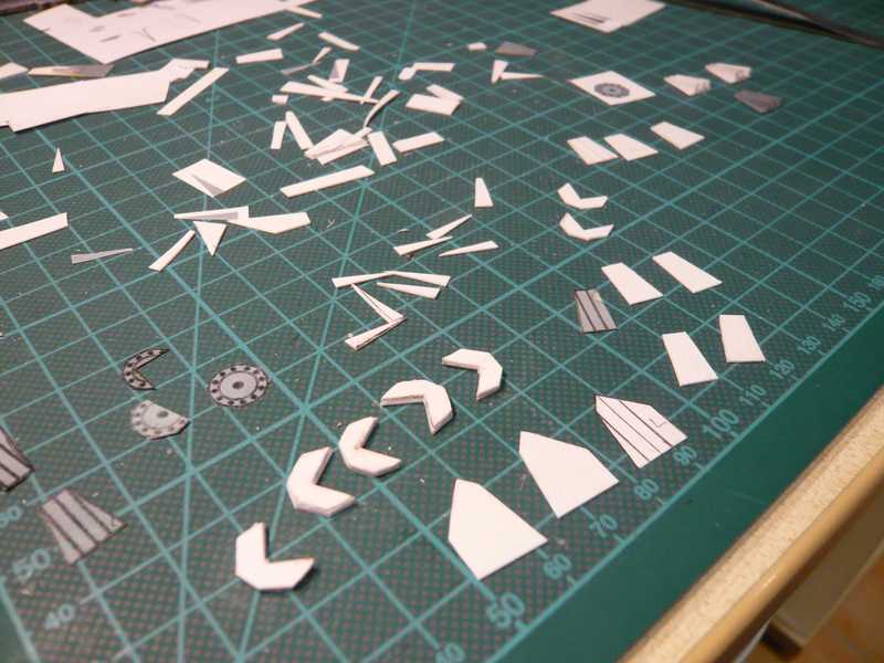 And here are the next steps of the fitting:  That is first the angle bracket (1.5 mm) with the main plate (0.5 mm), both from Sheet. Who looks exactly, the difference to the AXM template will recognize. Next the ribs (0.5 mm) had his turn, and so the mite grows then over continues to the corner. 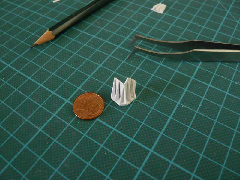 Now only a rear rib is missing to the Side 1, and then there was already the final fitting, which fit already completely properly and pleases me so also well.  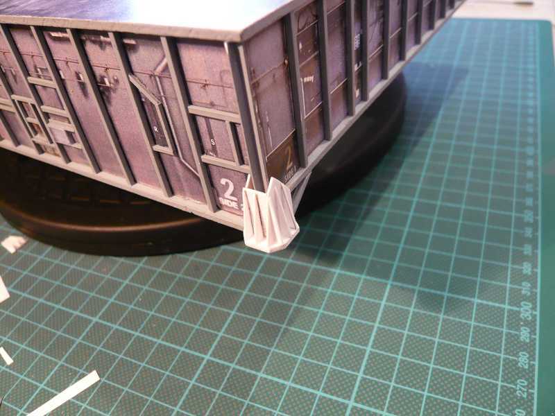  And here is the corner MMI for the right corner on Side 1. Before it already lie the angle plates for the two rear corner MMI's at Side 3 and the templates for the side panels. 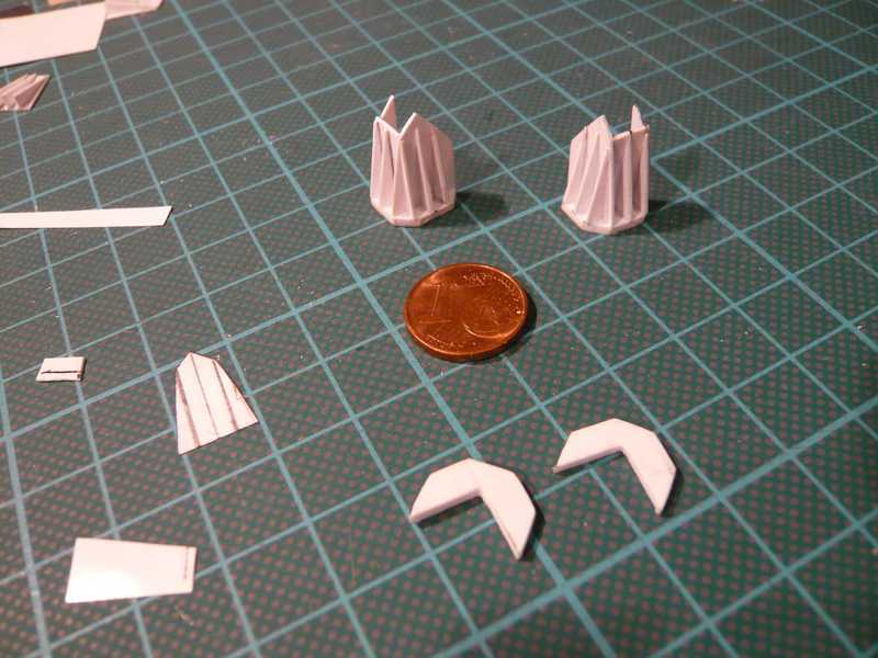 And then still fast a picture of the fitting. 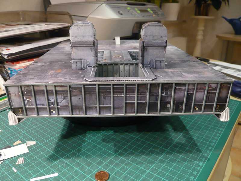 And thus to the corner MMI's to the Side 3, which see actually exactly the same as at the Side 1, as one can see in the following pictures. Here the MMI opinion of the rear end of the Side 4, at the transition to the Side 3,  Source: NASA and here the opinion behind the corner, from the Side 3. 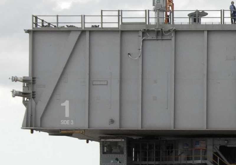 Source: NASA The individual parts for the remaining MMI's lie here already.  Those are now the six MMI's after their completion. 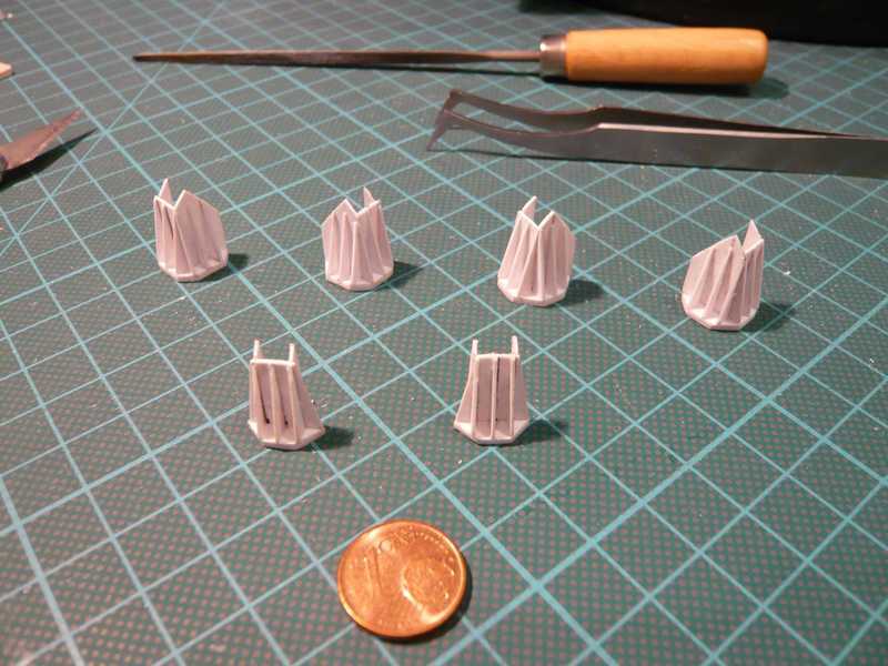 Now the parts are cleaned still of last finishing and then they finally can go for painting.
__________________
Greetings from Germany Manfred Under construction: Launch Pad 39A with Challenger STS-6 (1:144) Last edited by spacerunner; 10-11-2016 at 06:52 AM.
|
| Google Adsense |
|
#46
08-11-2013, 08:42 AM
|
||||
|
||||
|
39a with Challenger...
Manfred,
Your work is a continuing piece of museum quality craftsmanship! Bill  p.s. - I guess you already know this but Pad 39a was the pad used for the lunar launches!
__________________
----------------------------------------------- Seems to have been Deliberately Buried ----------------------------------------------- Where did Gunter Wendt ? 
|
|
#47
08-11-2013, 03:52 PM
|
||||
|
||||
|
Thanks Bill for your encouraging compliments.
Yep I know the Apollo history. The three Shuttle MLPs were originally constructed for the Apollo Program, known simply as the Mobile Launchers (ML), with the LUT. With the advent of the Space Shuttle Program, the three MLs were modified extensively for use with the new shuttle vehicle. First of all ML-3 was rebuilt into the first "Mobile Launcher Platform" MLP-1, then ML-2 into MLP-2, and finally ML-1 into MLP-3. And I'm building MLP-2, which was first used for the first Challenger mission STS-6 (04.04.1983).
__________________
Greetings from Germany Manfred Under construction: Launch Pad 39A with Challenger STS-6 (1:144) Last edited by spacerunner; 10-11-2016 at 06:53 AM.
|
|
#48
08-11-2013, 07:00 PM
|
||||
|
||||
|
Quote:
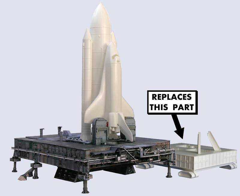
i have this exact same setup sitting in my closet you really make me want to dig it out and play with it. will be watching this thread with most interest to see how you git er done... only part i dont have is the educraft set will like to see how that fits into the scene replacing the standard part... wondering if it will be worth the cost to change it out... thanks for sharing this awesome project. engima Last edited by spacerunner; 10-11-2016 at 06:54 AM.
|
|
#49
08-11-2013, 07:23 PM
|
||||
|
||||
|
Imo it is extremely worth the cost. Its worth the extra detailing for all of the work you would have put into the shuttle.
Manfred, great work as always. I can't wait to see more :D
__________________
Mohammed Aly Current Projects LUT, Pad 39A
|
|
#50
08-12-2013, 04:26 AM
|
||||
|
||||
|
Thanks Guys for your nice compliments and comments.
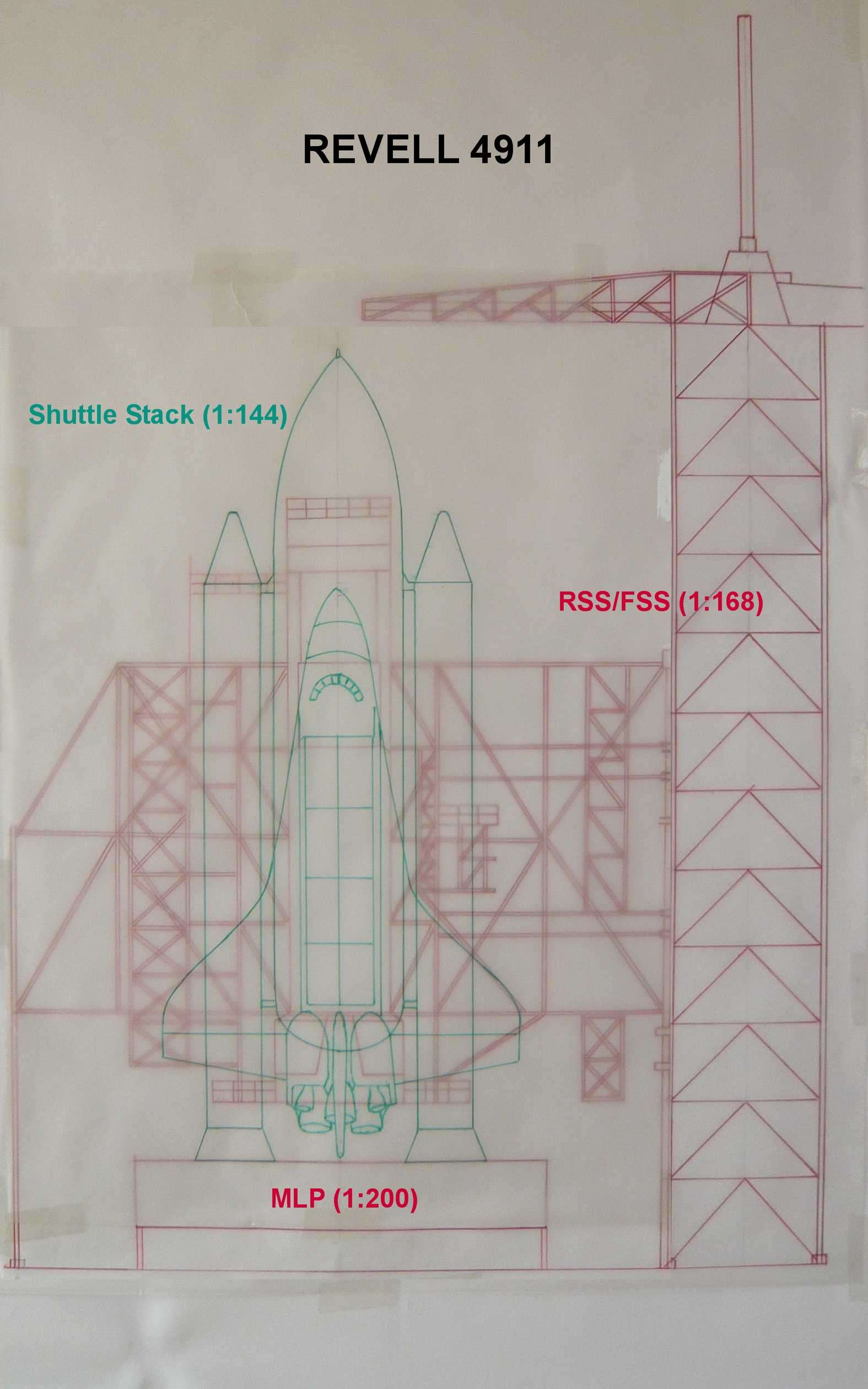
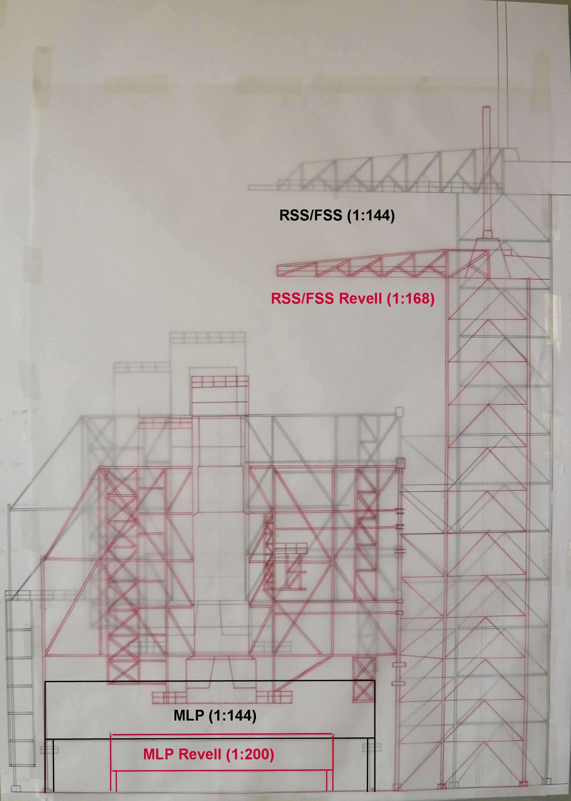
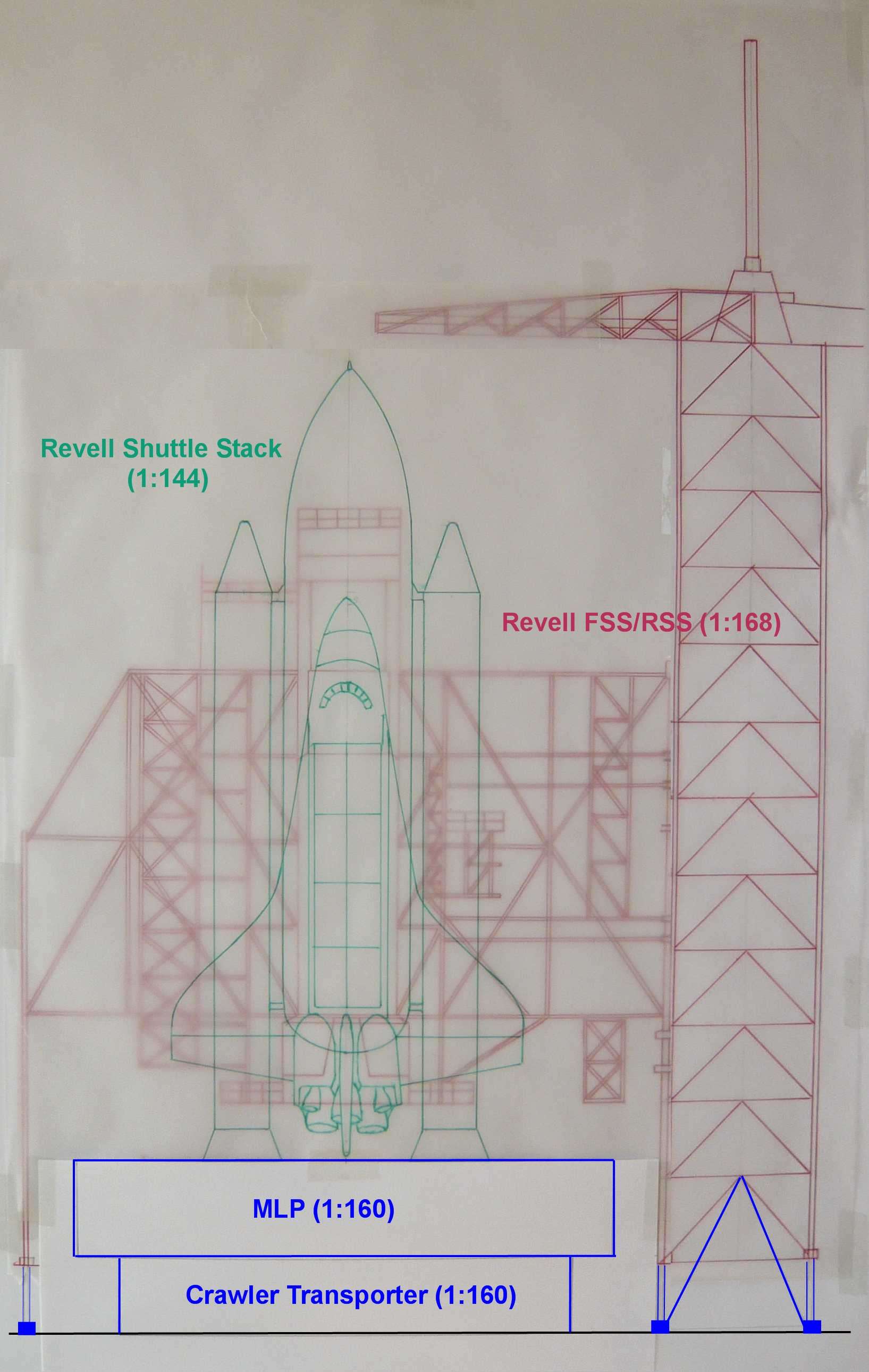
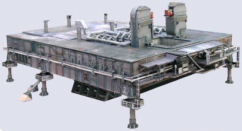
The main problem of the old Revell Kit 4911 (1:144) is the too small MLP, it doesn't visually fit to the overall appearance of the Launch Tower FSS & RSS. Therefore, and because I don't want to build the launch tower only OOB I would like to make the compromise and adjust the scale of the MLP and the crawler to 1:160.
__________________
Greetings from Germany Manfred Under construction: Launch Pad 39A with Challenger STS-6 (1:144) Last edited by spacerunner; 10-11-2016 at 06:56 AM.
|
| Google Adsense |
 |
|
|


 Linear Mode

