


|
|
|
#791
 05-21-2015, 11:44 PM
|
|||
|
|||
|
I am truly amazed at the level of detail this shuttle pad has, when its finished are you going to get a glass display case for it?
-RunwayOneSixRight (Matthew) 
|
|
#792
05-22-2015, 12:14 AM
|
||||
|
||||
|
Thanks Matthew for your nice words.
  Yep, this is a problem with which I have to deal with me later. Yep, this is a problem with which I have to deal with me later.  I'll need some kind of display case to protect the pad from the dust.  
__________________
Greetings from Germany Manfred Under construction: Launch Pad 39A with Challenger STS-6 (1:144)
|
|
#793
05-22-2015, 01:58 AM
|
||||
|
||||
|
I have just caught up with this project.
My jaw still aches from hitting the floor so many times!! Stunning detail work. Amazing! You have more patience then I will ever have! 
__________________
Once a King, Always a King. But, once a Knight is enough!
|
|
#794
05-22-2015, 03:31 AM
|
||||
|
||||
|
Thanks for your nice compliments!
Yep, never ending patience is absolutely necessary for such tiny crazy stuff.  This Firex line with its tiny supports and nozzles was a stressful challenge,  but the effort was worth it and I'm very happy with the result so far. but the effort was worth it and I'm very happy with the result so far. 
__________________
Greetings from Germany Manfred Under construction: Launch Pad 39A with Challenger STS-6 (1:144) Last edited by spacerunner; 09-26-2016 at 05:22 AM.
|
|
#795
05-22-2015, 03:56 AM
|
||||
|
||||
|
Quote:

__________________
Once a King, Always a King. But, once a Knight is enough! Last edited by spacerunner; 09-26-2016 at 05:23 AM.
|
|
#796
05-26-2015, 12:52 PM
|
||||
|
||||
|
Hi Manfred...I've been in the background still following your amazing build here. I'm so impressed with your continuing dedication on this project! Excellent work!
Bill
__________________
----------------------------------------------- Seems to have been Deliberately Buried ----------------------------------------------- Where did Gunter Wendt ? 
|
|
#797
05-26-2015, 05:07 PM
|
||||
|
||||
|
Thanks Bill for your nice compliments and continuing interest.
 Stay tuned, the pipe show will go on.
__________________
Greetings from Germany Manfred Under construction: Launch Pad 39A with Challenger STS-6 (1:144) Last edited by spacerunner; 09-26-2016 at 05:01 AM.
|
|
#798
05-27-2015, 07:56 AM
|
||||
|
||||
|
Hi together,
so, let's go to at last thicker SSWS pipes and the associated supports.  For this I can initially resort to my erstwhile pull-ups before the conversion of the SRB holes when I had started already with the SSWS. Who wants to track once more precisely, can please scroll back to pp. 44 (#219).  Unfortunately, I can forget my former pipes (1:160) as they are a little too narrow and too short for the 1:144 holes.  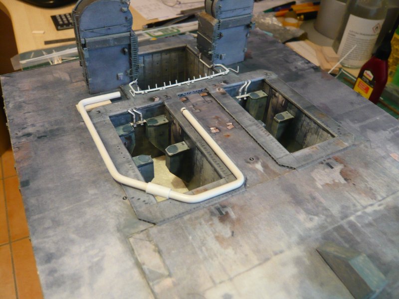 In the following general layout drawing the position of the pipe supports of the 24'' line (Ø 4,0 mm) is marked, and there are respectively 18 supports around each SRB hole.  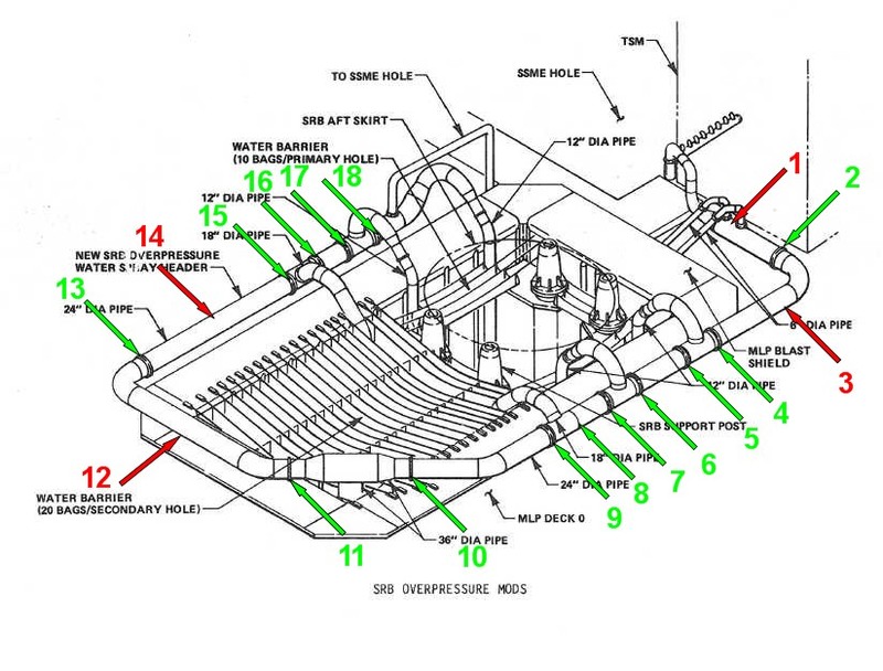 Source: NASA At the green marked points 14 supports are located with closing clamp bands to replace these line segments as needed or to service, as can be seen in the next picture. The remaining 4 supports on the red marked points having no such clamp bands. When evaluating the photographic material I have discovered some supports (1, 3, 8, 12, 14) and supplemented, which are missing in the drawing.  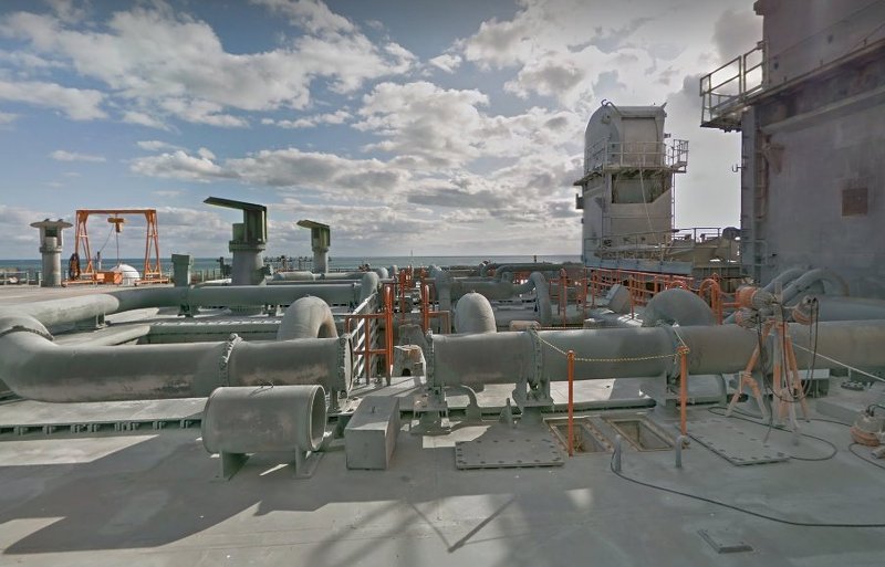 Source: NASA (Streetview) Furthermore, it should be noted that all supports are standing on the MLP deck, while no. 10, 11 and 12 are on the Blast Shield. Accordingly, these supports have a shorter foot and also slightly different structure. 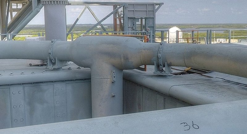 Source: NASA As has been shown in a previous post (Reply #790), the 24'' pipe (Ø 4,0 mm) behind the support 1 tapers to 14'' (Ø 2,5 mm) which is why the local support has a special structure too. 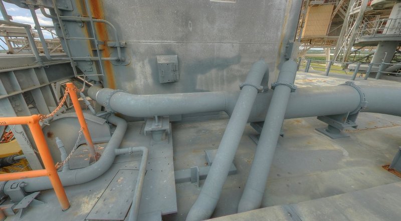 Source: NASA All remaining supports have otherwise the same structure as it is clearly seen here. 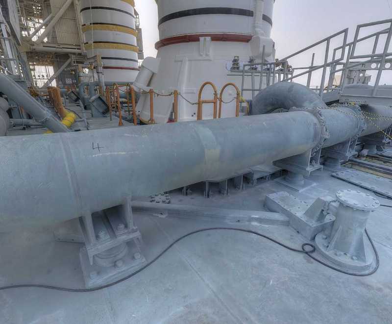 Source: NASA Such support I had at that time already been scratched, I actually had quite liked, 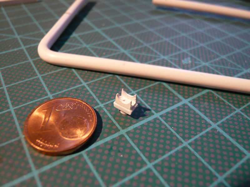 but from today's perspective the dimensions (L=5.0 mm, W=3.2 mm), and in particular its clear height (4.0 mm) seem to be a bit too large. And with that problems in determining the scaled dimensions inevitably reveal, which unfortunately is often difficult due to perspective distortion of reference photos. In David Maier's Paper kit these supports are unfortunately only hinted, whereat the clear heights of 2.5 mm respectively 1.5 mm appears to be too low. 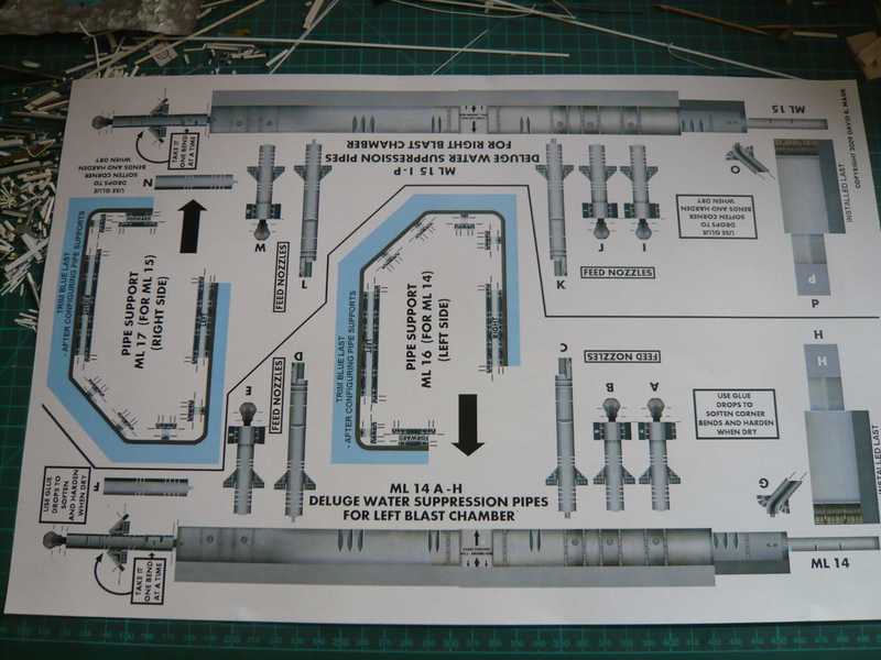 Consequently, I made again a lot of measurements and estimates based on different images and perspectives  and now I tend to a clearance of 3.5 mm on the deck, respectively 2.0 mm on the SRB Blast Shields, that are 1.5mm high with me. and now I tend to a clearance of 3.5 mm on the deck, respectively 2.0 mm on the SRB Blast Shields, that are 1.5mm high with me.  This arrangement I have now simulated with my old pipe in a test, for this I have used provisional support dummies of corresponding height. And in order to see how and to what height the line arrives at the inner corner of the TSM, I have provisionally glued the two tapers at the front end. 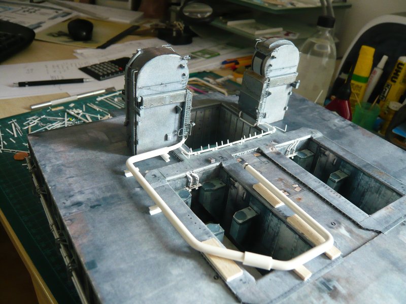  As this support arrangement actually fits quite well and I also like the look, I will now try to scratch build two matching support patterns.
__________________
Greetings from Germany Manfred Under construction: Launch Pad 39A with Challenger STS-6 (1:144) Last edited by spacerunner; 09-26-2016 at 05:13 AM.
|
|
#799
06-01-2015, 06:39 AM
|
||||
|
||||
|
Hello together,
on the problems arising from the perspective distortions of the images when determining the dimensions of the items needed for the supports I had already pointed out. As an illustration, I have this image of the thick 24'' pipe whose diameter (4 mm) usually was the reference value for the conversion to the model scale. 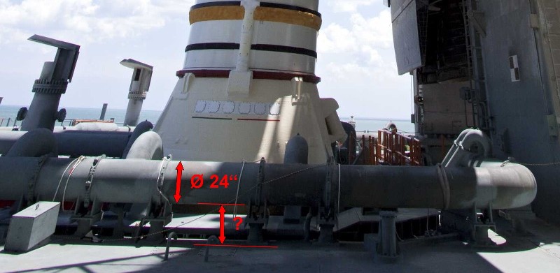 Source: NASA BTW, the estimation of the clear height especially had given me a lot headache, but that is important, especially since it is identical to the height of the support. As you can see here, the clear height should then be roughly equivalent to the pipe diameter, or about 4 mm. Because the evaluation of other photos from different perspectives with better resolution but gave predominantly smaller values by 3 mm, I'd at the end spoiled for choice and had to decide. And as already mentioned, I have now committed myself to 3.5 mm respectively 2.0 mm. 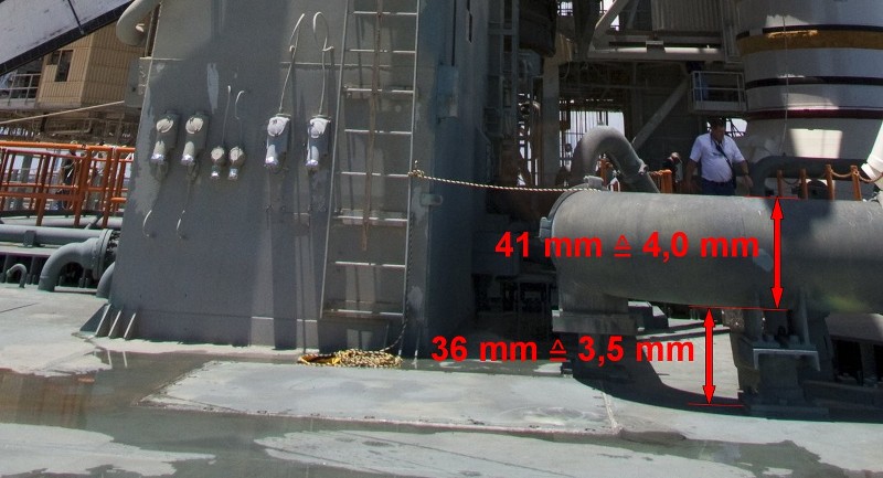 Source: NASA And so now, but the actual work. For the most frequently occurring support (Type 1) next to the thick 24'' ring line I've been thinking about the following structure, which consists of five elements on which I've fiddled for a while. Therefore, at first I was interested to see whether this structure would be realizeable at all.  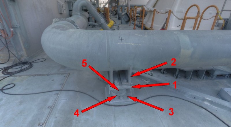 Source: NASA As a basic element (1) I will this time use an Evergreen channel (2,5x1,1 mm), and for the two crescent-shaped supports (2) and the base plate (3) Styrene (0,25 mm). The foot consists of two parts, the upper part (5) is a jewelry pearl (Ø 1,3x1,2 mm) and the lower part (4) a Styrene disk (Ø 1,5 mm). While the elements of the lower part (1, 3, 4, 5) should guarantee a uniform height, it will in particular depend on how to achieve the small crescent supports possibly with precise curves and always with the same height, so that all 30 supports at the end are also the same height. And these sickles I'll punch with my Punch & Die Set, the maximum diameter accidentally is 4 mm.  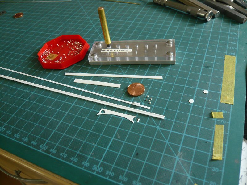 Although on the reference photos everything looks relatively large in the measurement and scaling, at the end there are but rather small parts. And from the punched sickle remains at the required height and width also not much left. The uniform spacing of these crescents results from the fact that they are glued on both sides with MEK to a Styrene Strip (0,25x1,5 mm), which is then glued to the Evergreen Channel what I have previously tried it out with two test strips. And so here are the necessary parts. To assemble the foot parts I've been thinking about, to thread them on a pin through a centering bore and then to glue in order to ensure a uniform alignment. 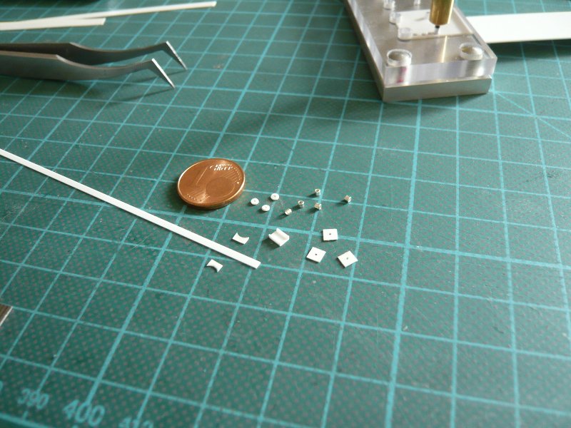 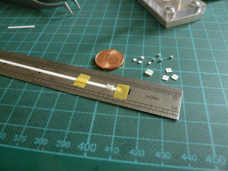 After alignment and fixation the items of the upper part gluing was made again with MEK, which has really proven for such mini-contacts. 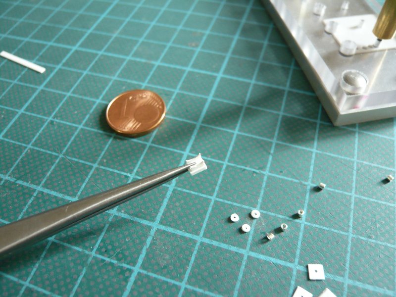 The gluing of the foot parts, however, is a little more difficult, since the glass bead must be carefully glued with CA, but this can remain unfortunately also stick to the needle. 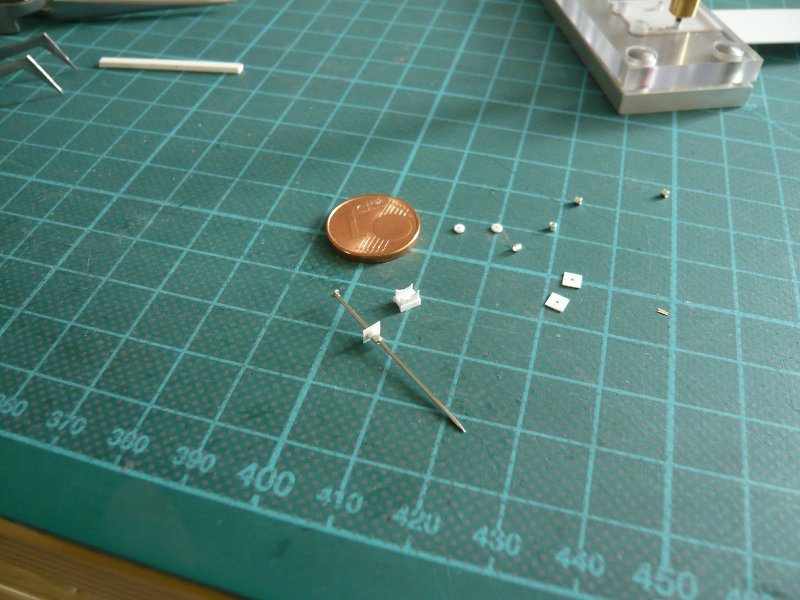 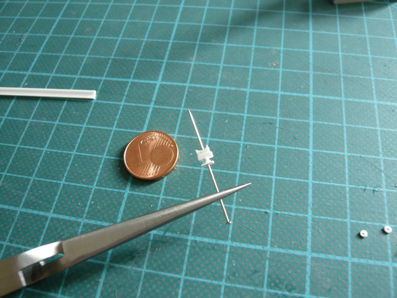 This has also so far worked, so I was initially glad in view of the feasibility of construction. 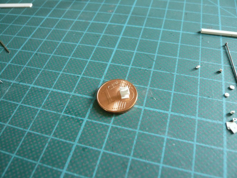 To be continued ...
__________________
Greetings from Germany Manfred Under construction: Launch Pad 39A with Challenger STS-6 (1:144) Last edited by spacerunner; 09-26-2016 at 05:16 AM.
|
|
#800
06-01-2015, 06:40 AM
|
||||
|
||||
|
Here comes the rest.
After detailed contemplation of my respectable result but I have decided to enlarge the disks on the base plate to 1.7 mm in diameter (left), what should better fit into the picture.  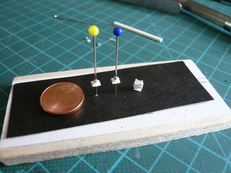 But my joy did not last long unfortunately, because in the next handles the support disintegrated again in two parts.  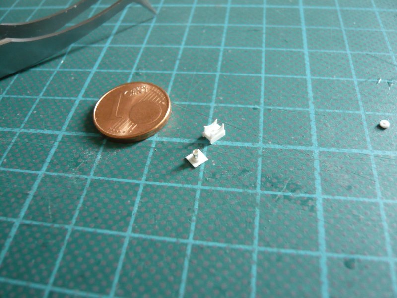 So I had to think about another solution instead of the CA gluing, which has been obvious actually.  For why should I not stay with the MEK gluing and use a Styrene rod Ø 0,5 mm as a centering aid, which could remain in the support? For why should I not stay with the MEK gluing and use a Styrene rod Ø 0,5 mm as a centering aid, which could remain in the support?  Why did I come not immediately to this solution ... Why did I come not immediately to this solution ...  And so one of the Nozzles has offered itself that was still close.  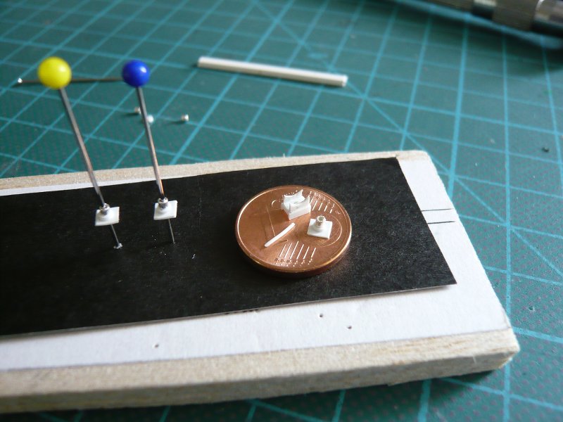 No sooner said than done, this little rod I first glued into the upper part, then strung the lower part and glued, 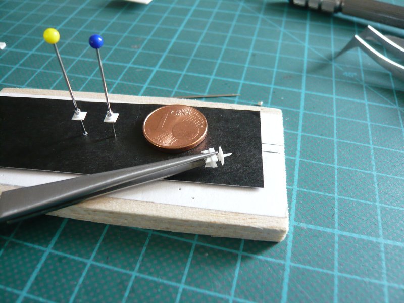 then only separated the rest under the base plate, and the case was settled. 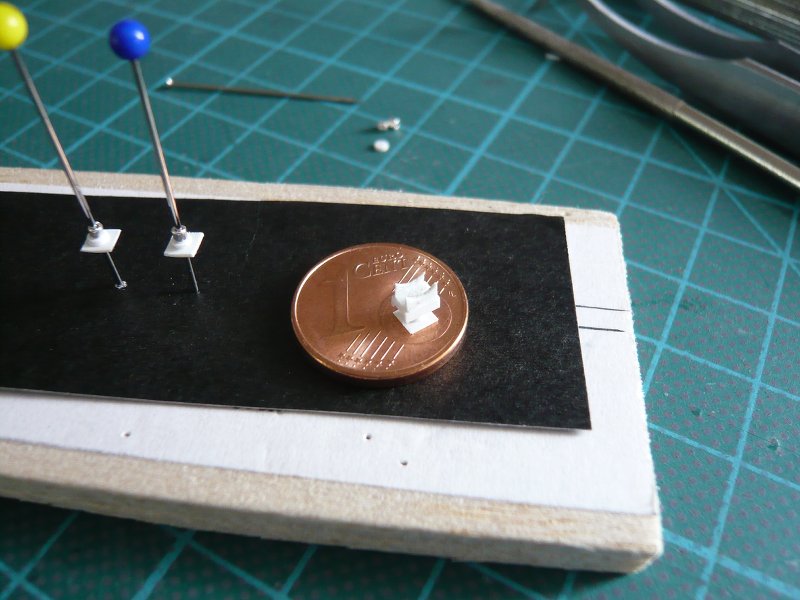 And this support is now hopefully more stable and can withstand a little more.
__________________
Greetings from Germany Manfred Under construction: Launch Pad 39A with Challenger STS-6 (1:144) Last edited by spacerunner; 09-26-2016 at 05:19 AM.
|
 |
|
|


 Linear Mode

