


|
|
|
#911
 10-31-2015, 06:10 PM
|
||||
|
||||
|
Hello guys,
because the chunky railings has left me no rest, I have tested my PE railings of ABER in order to have a comparison with a true to scale part.  This railing can be found at ABER under Ship relings (1:150) and the dimensions of which should fit almost perfectly, especially as they are only 0.2 mm "thin". 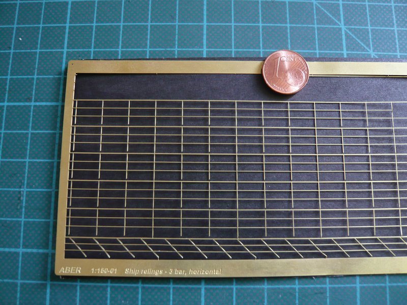 So I've even cut out an useable strip, 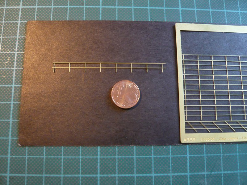 and have mounted provisionally on the west side of Level 195 at the local gap in the railing, which there is not existing because of the freedom of access to the rescue baskets of EES, even not these outer short pieces, what I had already mentioned.  But through this gap one can see the difference from the 1 mm "thick" railings of the Revell Tower very well what has impressed me. But through this gap one can see the difference from the 1 mm "thick" railings of the Revell Tower very well what has impressed me.  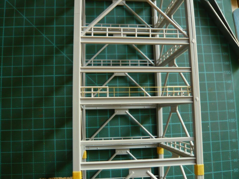 And since we are talking just about, the overlying cross beam (the old kits) does not exists at this place. It could be that Revell had tried to indicate the cross beam on which the ropes (Slide Wire) are attached, via which in the case of an accident the emergency the baskets slide down, who knows? But this cross beam is sitting a bit in front of the FSS framework, as you can see here. 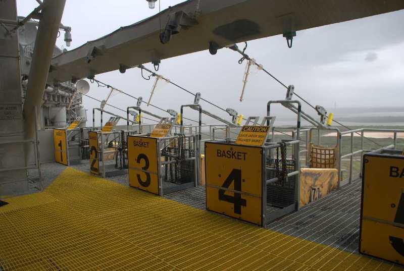 Source: NASA And here once more a taste one floor deeper on Level 175, where in the old kits both the railing and the diagonal braces completely lacking, and the cross beam is not true. Therefore the comparison with the chunky railing of the level below here is even better to see, I think.  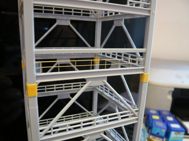 And the longer I look so, the more I reach the view that it would be worthwhile, perhaps completely replace the Revell railings, what do you think?  Because later will come then still the filigree grid floors, stairways and the elevator shaft of the LVM Detail Kits, which would then naturally harmonize well.  
__________________
Greetings from Germany Manfred Under construction: Launch Pad 39A with Challenger STS-6 (1:144) Last edited by spacerunner; 10-31-2015 at 06:22 PM. 
|
|
#912
10-31-2015, 06:55 PM
|
||||
|
||||
|
I say just go ahead and replace the railings. It may take a little time but it will probably pay off more in the end

__________________
PAPERENGINEER Designs in progress: -C-2A Greyhound -Br.1050 Alize
|
|
#913
10-31-2015, 09:47 PM
|
|||
|
|||
|
The difference in railing appearance is such that I really don't think you have any choice but to replace them Manfred. Paperengineer is right - your payoff in the end will be huge and your sense of relief will be palpable.
__________________
This is a great hobby for the retiree - interesting, time-consuming, rewarding - and about as inexpensive a hobby as you can find. Shamelessly stolen from a post by rockpaperscissor 
|
|
#914
11-02-2015, 04:57 AM
|
||||
|
||||
|
Thanks PE and Elliott for your encouraging response, meanwhile I am committed to replace the Revell railings and to use the PE parts.
A similar decision I had to make with the TSM ladders, and the use of the PE ladders was then also the right solution.
__________________
Greetings from Germany Manfred Under construction: Launch Pad 39A with Challenger STS-6 (1:144)
|
|
#915
11-02-2015, 05:59 AM
|
||||
|
||||
|
Hello everybody,
to round off the matter, today only briefly my conclusion about the planned changes of the FSS, of which no longer so much is left when you look at it realistically. On the Side beams nothing should be changed, except for the upper part after the transition from the Box Columns to the W profiles W14x193 and W14x61. While W14x193 in 1:168 would correspond to a 2.5 mm H-Beam, one could use a 2.0 mm I-Beam for W14x61. Since the gradual tapering of the square tubes a total of only is about 1 mm upwards, it can be approximately neglected. 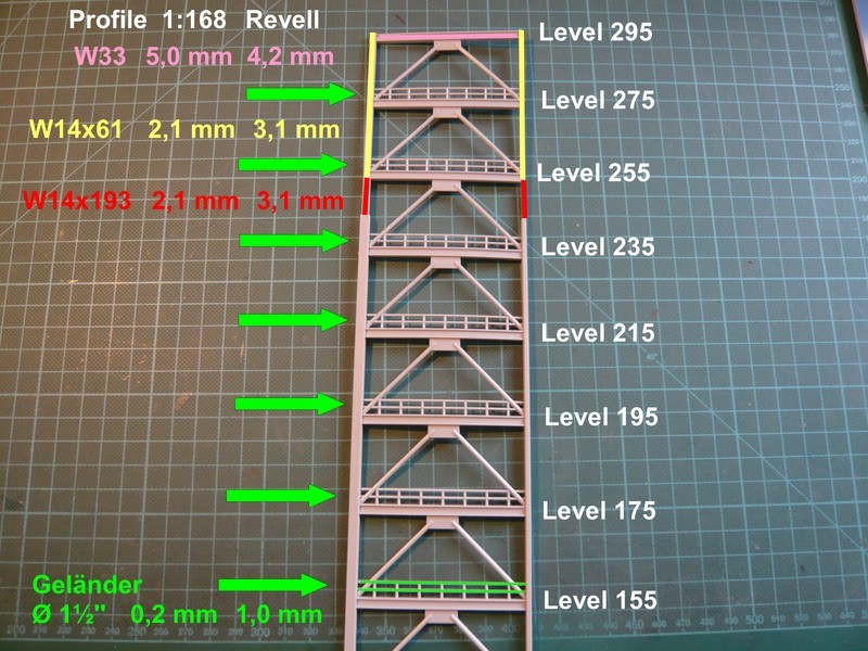 Also the Frame girders one should leave unchanged, since in their inner sides the PE grid floors of LVM are fitted. Only the top frame girder W33x118 could be replaced by an Evergreen I-beam (4.8 mm), since one anyway must intervene in the upper three levels. The Railings I will completely replace however and use for this the PE-railings of LVM, because they fit perfectly to this scale. 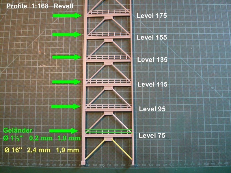 Consequently, one only need to exchange the lower eight Ø 16'' Diagonal braces, but as I said, the first floor is anyway too low and must be raised by approx. 8 mm, in order to bring it to 1:168. And then, of course still the installation of the additional floor, for which I had to decide me enforcedly.  Last not least, the FSS includes also the three Access Arms OAA, OVA, IAA, which I will also scratch build for the most part. All together a lot of tricky work.
__________________
Greetings from Germany Manfred Under construction: Launch Pad 39A with Challenger STS-6 (1:144) Last edited by spacerunner; 11-02-2015 at 06:11 AM.
|
|
#916
11-23-2015, 06:01 PM
|
||||
|
||||
|
Hello everybody,
so friends, after a fling penultimate Thursday for a (guaranteed not one-time) rendezvous with my "dream" woman Mriya (AN-225) on the Leipzig/Halle Airport,   whose preparation and follow has taken some time to complete, it will now go further on my Launch Pad. What has always been lacking is the analysis of the right support structure of the RSS, including the Hinge Column to FSS, with whom I have engaged myself in some detail. And as I have already suggested, this looks similar to those on the left with regard to undersized profiles.  This involves first of all the parts 22, 39, 41, 47 and 54 shown on the assembly guide.  And now I have noticed that the lower side parts of the front elevation below the RSS Main Floor are open to the fore, and not closed as in the Revell-RSS.  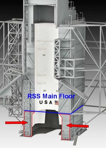 Source: Revell That looks here for the STS-6 at least so, as if these two platforms are open towards the front.  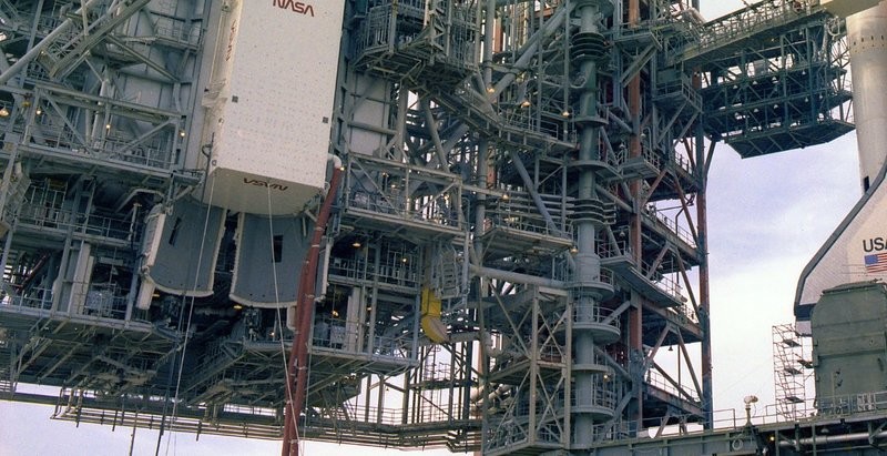 Source: retrospaceimages.com (STS-6) Therefore this one must be taken under a closer look.
__________________
Greetings from Germany Manfred Under construction: Launch Pad 39A with Challenger STS-6 (1:144)
|
|
#917
11-23-2015, 10:38 PM
|
||||
|
||||
|
That's awesome that you saw the 225. Keep up the good work with this project.
|
|
#918
11-29-2015, 05:02 AM
|
||||
|
||||
|
Thanks Konstantine and Hello everybody,
as you can see relatively well in this photo from 1983, the upper floor (APU Servicing Platform) extends deeper into the inside than the front wall as well as the subjacent APS Servicing Platform below the RSS Main Floor of the PCR. 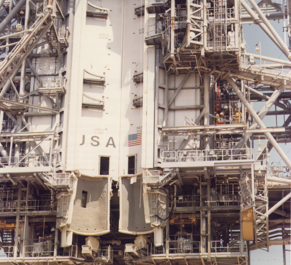 Source: John Duncan And both floors are also much wider than the PCR, which is not also true at Revell, and need to be broadened accordingly.  In any case, both floors are open towards the front, so one must remove the side panels of the front wall. And consequently, the LVM parts have to be adjusted with the railings, which form the front end. Another problem are the two OMS Pod Covers below the PCR Bay that are highly abstracted with Revell and sit too far inside, namely where the two APU and APS Servicing Platforms are.  Both Revell parts can, if at all, only as an outer shell to be used, because towards the front or on the inside the Pod Covers have indeed an approximately semicircular shell shape which is adapted to the contours of the OSM pods. Here one can see the installation of the OMS Pod Covers, how Revell has imagined, but which is not correct. As noted above, the front sides below the RSS Main Floor must be removed which then allow a view into the interior of the APU and APS Servicing Platforms. As can be seen on the very first image, the upper front edge of the pod cover is not flush with the PCR main doors but are significantly more forward on. Presumably, the rear edges will be flush. And this was the back of the Pod Cover, which were mounted on the Pad 39B, and I mean it might be the left cover. A photo of the inside structure would be interesting, of course, but unfortunately I have no HiRes images. 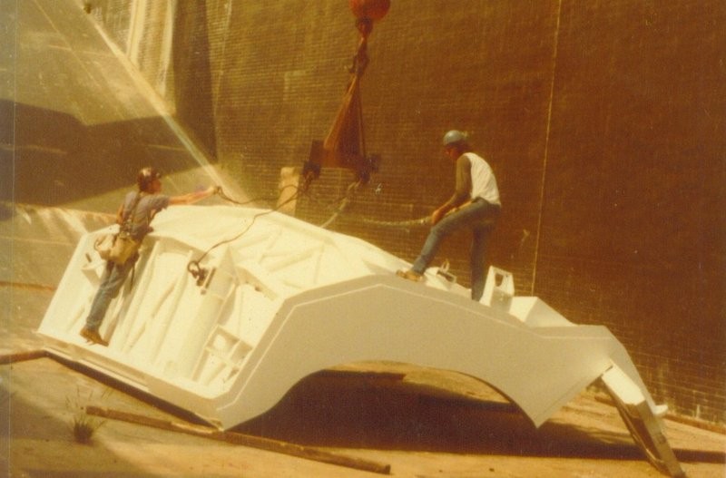 Source: NASASpaceflight.com (J. MacLaren) What is interesting is the structure of the two missing platforms that need to be completely scratch built.  In the meantime, I have found two NASA panorama that show both platforms in detail and thus constitute a great help. In the meantime, I have found two NASA panorama that show both platforms in detail and thus constitute a great help.  And so it looks on the lower APS Servicing Platform, which has a large cutout for the orbiter tail in the middle that extends close to the PCR back wall. 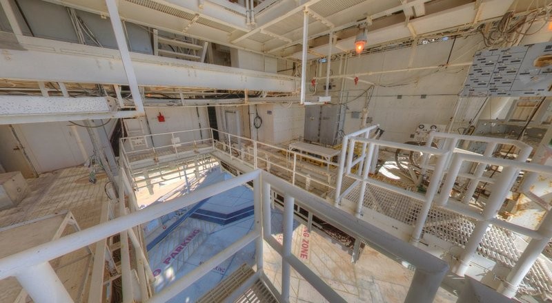 Source: NASA As can be seen on the panorama, the back ceiling of the platform hangs a bit deeper, which can be seen in the next panorama of the APU Servicing Platform clearly. 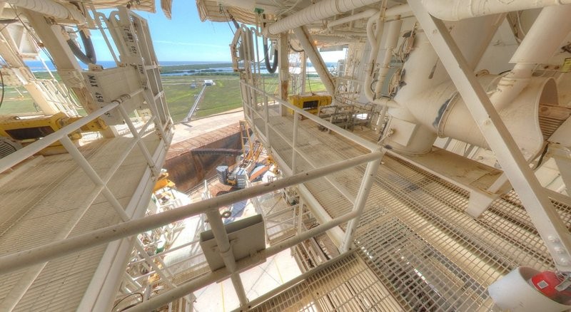 Source: NASA 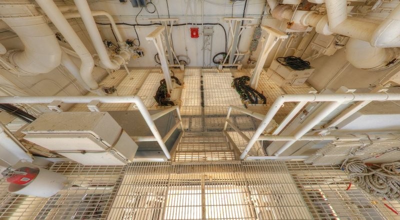 Source: NASA But look arround to your heart's content. And so now the structure of the two platforms looks relatively clear, which is but a tricky challenge for scratch building.
__________________
Greetings from Germany Manfred Under construction: Launch Pad 39A with Challenger STS-6 (1:144)
|
|
#919
12-13-2015, 10:35 AM
|
||||
|
||||
|
Hi everybody,
still a short addendum to the upper connection of the OMS Pod Covers to the PCR Bay, one can clearly see from this HiRes. photo of STS-1. 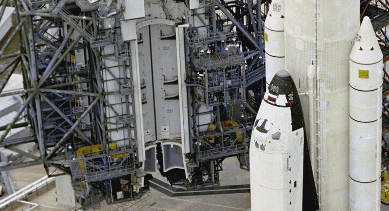 Source: NASA And it is true, as I suspected it, because the Pod Covers sit completely in front of the RSS Main Doors, so also this detail would be clarified. 
__________________
Greetings from Germany Manfred Under construction: Launch Pad 39A with Challenger STS-6 (1:144)
|
|
#920
12-13-2015, 10:39 AM
|
||||
|
||||
|
Nice to see this is still ongoing. Two weeks is a pretty long break for your project, so I got worried!

__________________
PAPERENGINEER Designs in progress: -C-2A Greyhound -Br.1050 Alize
|
 |
|
|


 Linear Mode

