


|
|
|
#1991
 08-10-2019, 04:39 PM
|
||||
|
||||
   As the test fitting of the Cable tray with the glued box shows, the seat is quite neat, so that only the sloping bottom side would be something to straighten.  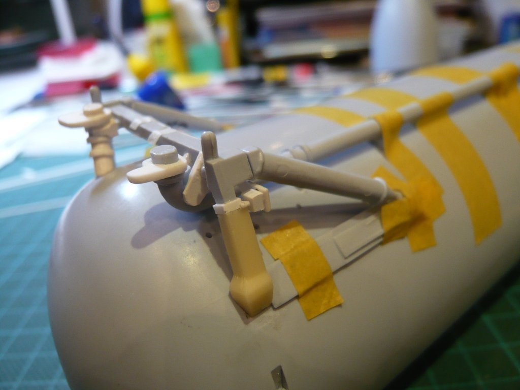 Then only the cable connection would have to be attached, after which it could then continue on the other side.  
__________________
Greetings from Germany Manfred Under construction: Launch Pad 39A with Challenger STS-6 (1:144) 
|
|
#1992
08-19-2019, 06:10 AM
|
||||
|
||||
|
Hello everybody,
in the meantime, I've attached this Cable connection between the Vertical strut and the Distribution box, for which I've glued two tiny pieces of Evergreen Strip which are barely noticeable.  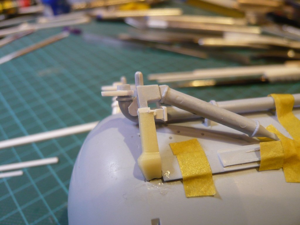 And now to the other end of this Cable Tray in the red circle, which after the arc at the end firstly goes down and then immediately runs rearward in a short 90° arc underneath the Crossbeam. 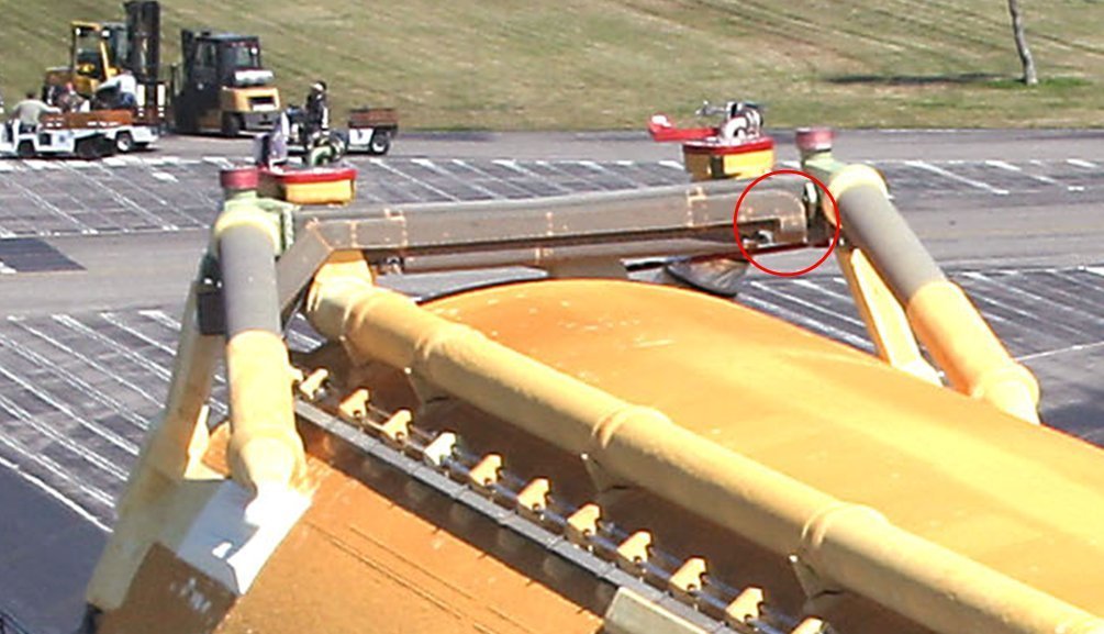 Source: NASA This course can be followed in the following photos.  Source: NASA 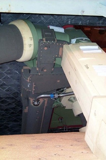 Source: georgesrockets.com (George Gassaway) 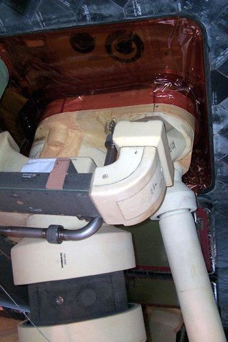 Source: capcomespace.net In this drawing, the course of the two Cable trays is simplified depicted, but what is helpful for scratch-building.  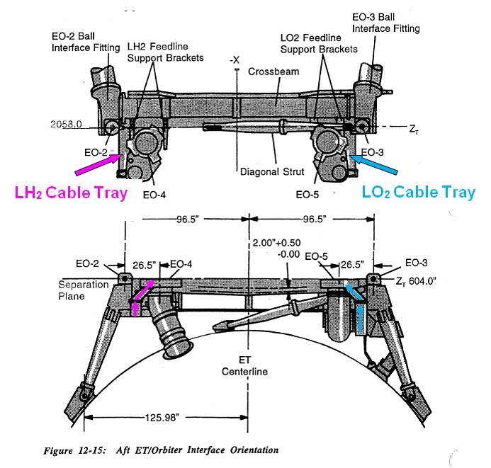 Source: System Definition Handbook SLWT, Vol. I (Lockheed Martin) Behind the crossbeam follows at the end of the cable tray the angled transition of the parts with TPS Cladding (2, 3, 4, 5) up to the Umbilical Plate under the orbiter, which seems to be difficult to scratch due to the minimal dimensions of the parts,  especially since the clear height between the Cable Tray and the Umbilical Plate is only 3 mm, from what the height of the CT transition to 4 mm results, which should become quite tricky. especially since the clear height between the Cable Tray and the Umbilical Plate is only 3 mm, from what the height of the CT transition to 4 mm results, which should become quite tricky.  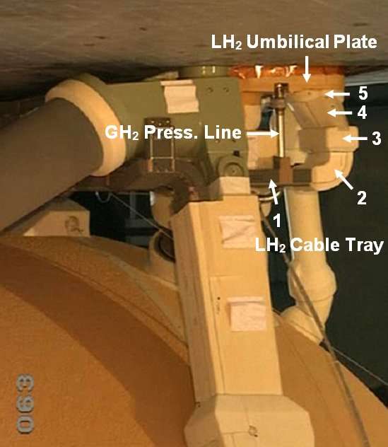 Source: georgesrockets.com (George Gassaway) 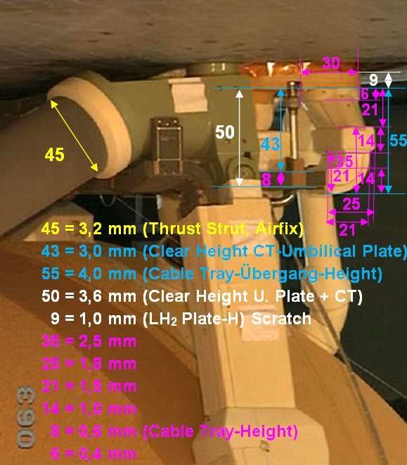 Afterwards I've tried the arc of the Cable Tray on the front of the Crossbeam with the help of my Balsa & Bending Technique. 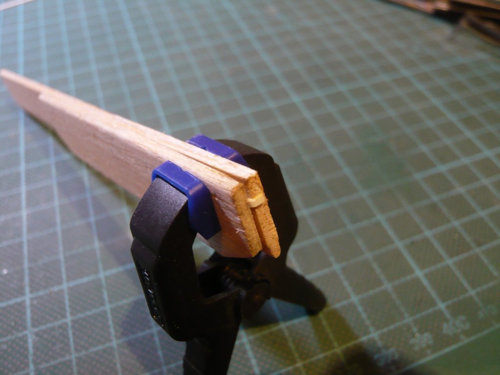 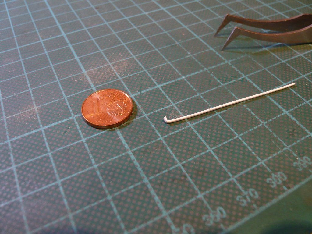 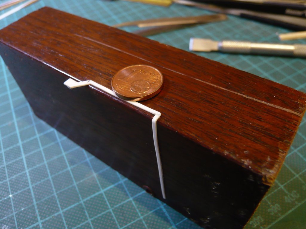 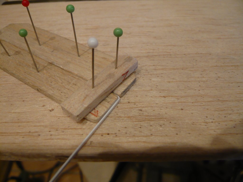 During mounting one has to make sure that the Cable Tray is not directly in contact underneath the Crossbeam but sits on a small spacer (0,4 mm) which is already glued here. 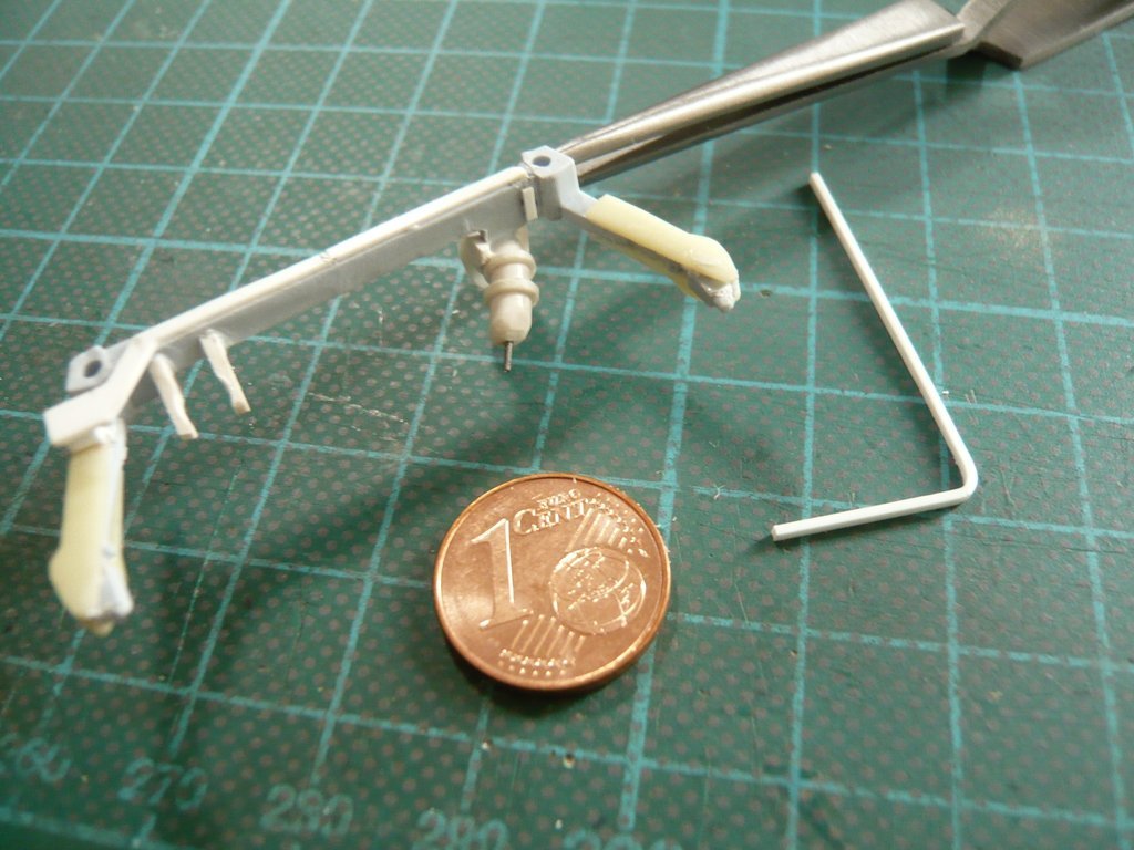 As the test mounting shows, however, from the arc would leave almost nothing left, which would probably complicate a flush connection.  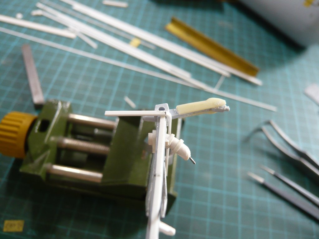 Therefore, it will probably be better if the cable tray is first glued to the front with a bit of supernatant, after which a matching strip is glued in the interspace which then is rounded. 
__________________
Greetings from Germany Manfred Under construction: Launch Pad 39A with Challenger STS-6 (1:144)
|
|
#1993
08-19-2019, 08:46 AM
|
||||
|
||||
|
And this construction I've tested provisionally with tape,
 and was surprised that the clear height between the Cable tray (0,6 mm x 1 mm) and the Umbilical plate is actually 3 mm and thus is perfectly in accordance with my previous estimates of the measurements.  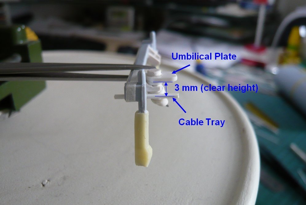 And this is a first attempt to make the TPS arc (part 2) from a rectangular profile 1,5 mm x 3,2 mm, 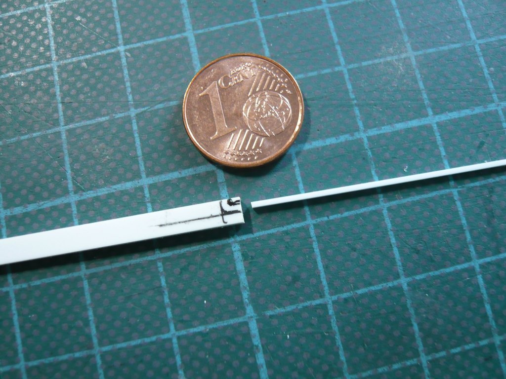 whereby I am looking forward to the result.
__________________
Greetings from Germany Manfred Under construction: Launch Pad 39A with Challenger STS-6 (1:144)
|
|
#1994
08-21-2019, 03:48 PM
|
||||
|
||||
|
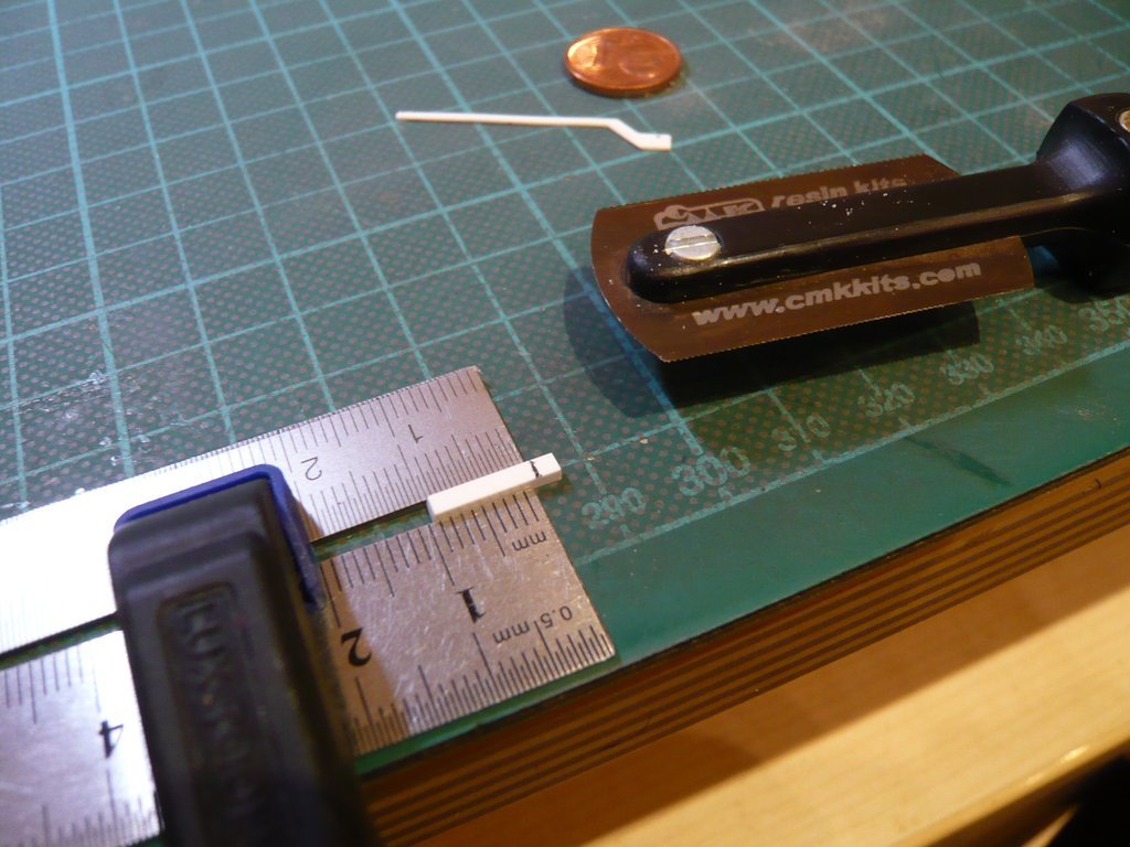
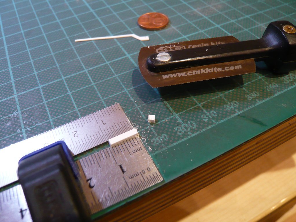
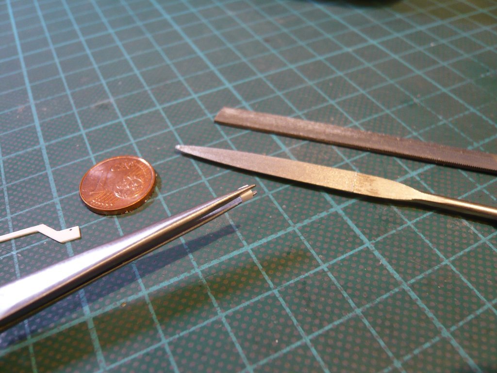
Hello everybody,
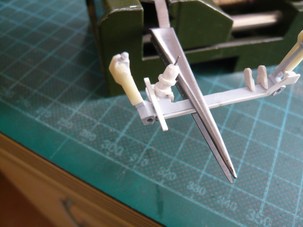
but first I've continued with the LH2 Cable Tray and the associated tiny parts of the transition, which are all in the millimeter range and thus extremely tricky to handle, what only is feasible under the Headset magnifying glass. During processing, I carefully approached from all sides using my file set and my finest mini-saw (0,1 mm), whereby one must keep an eye on the required dimensions, which is for this bow 1,5 mm x 1,5 mm, which is why one has to measure again and again. 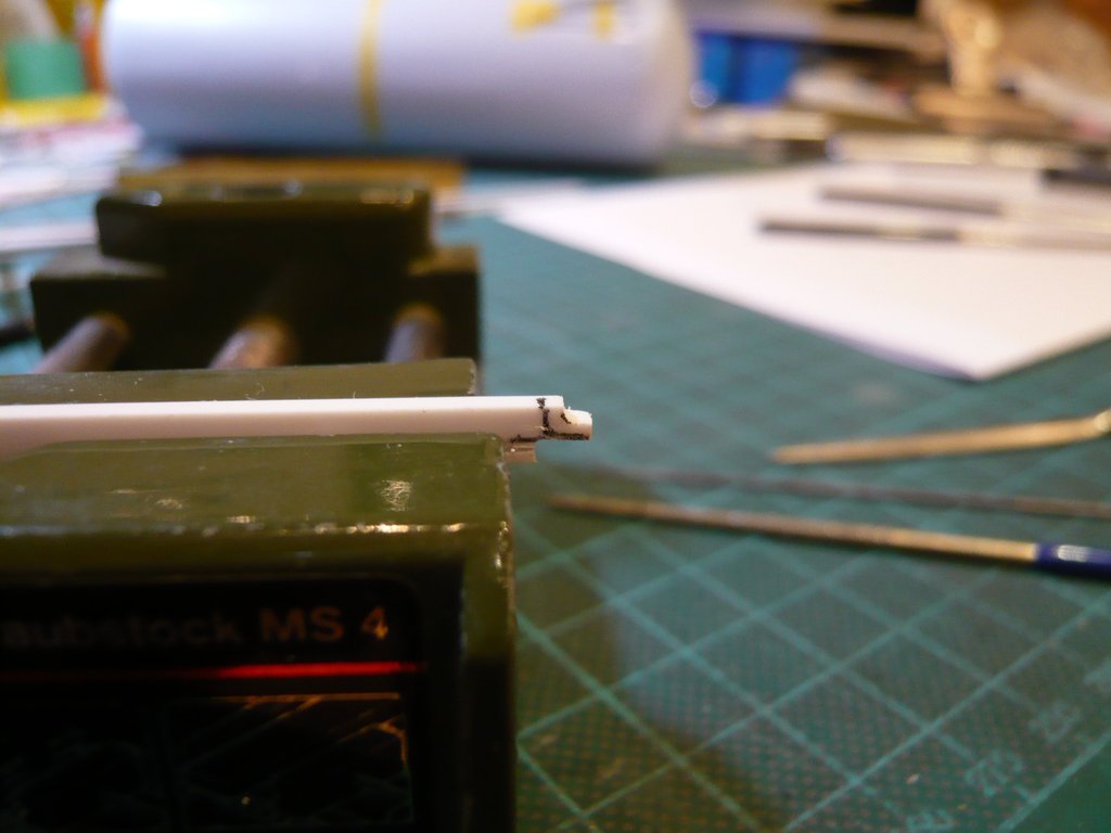 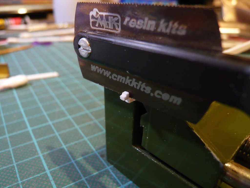 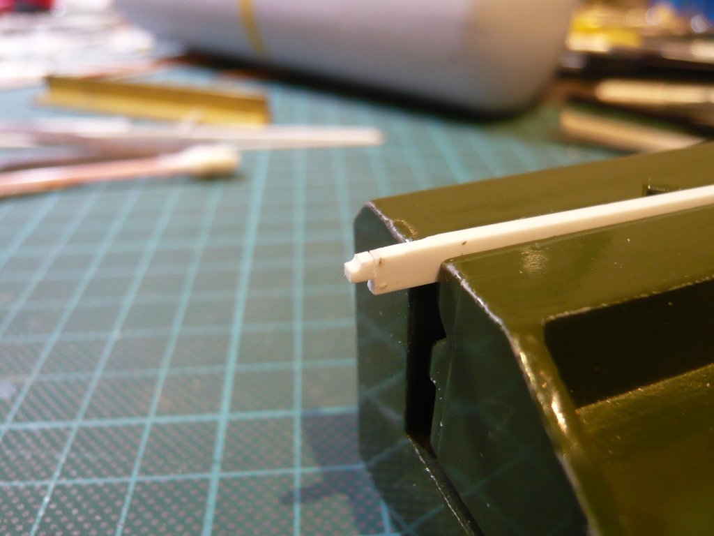 And since I prefer to work with a little bit of excess, a post-processing is still necessary, which becomes particularly tricky once the part has been sawn off. As a result, an undersize can quickly arise, which is not so good.  So, choosing the Rectangle profile of 1,5 mm x 3,2 mm was not exactly brilliant and has unnecessarily complicated the whole procedure.  That's why I used a Square profile 1,5 mm x 1,5 mm in the second attempt, which was much "easier" to handle, since the outer dimensions are already fit, and what I could have done better immediately.  At first I filed the rounding and then sawed off the length of 1,5 mm. However, care should be taken during the following processing of this mini-piece, 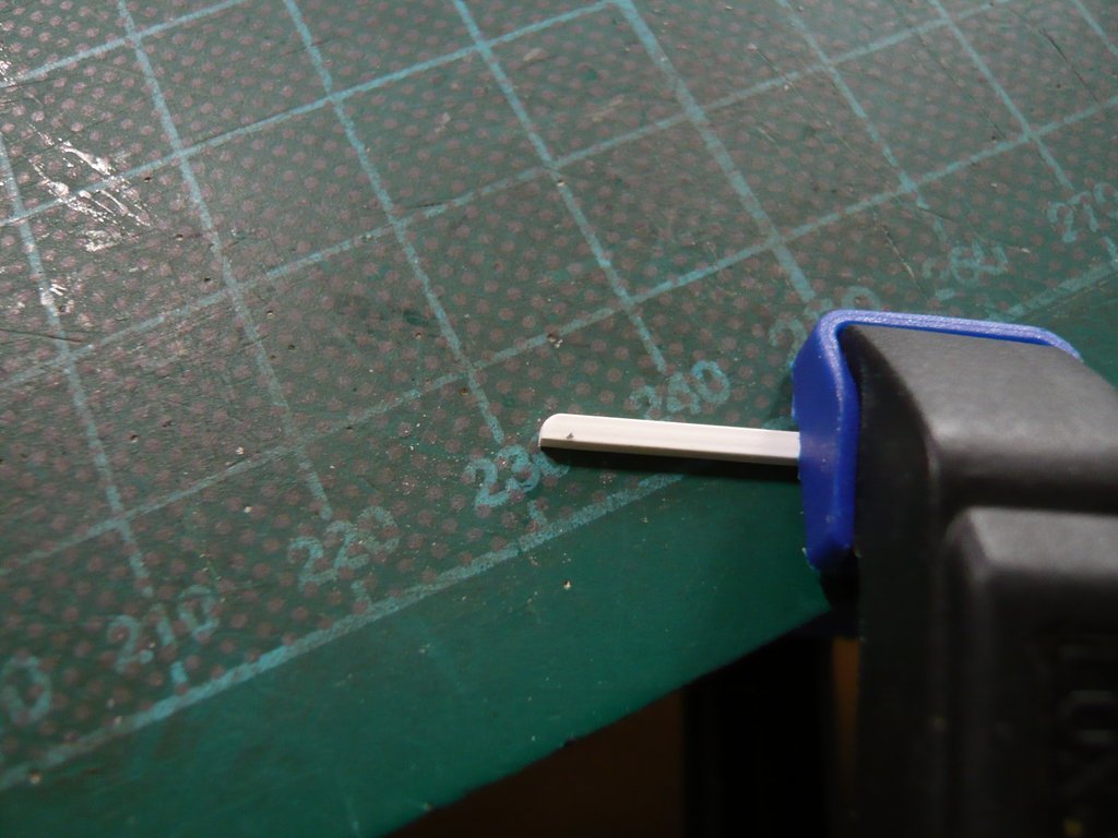 whereby I held it for filing the inner rounding with my Precision file (Ø 1 mm) in a Cross tweezer and at the same time supported it from below with the finger. 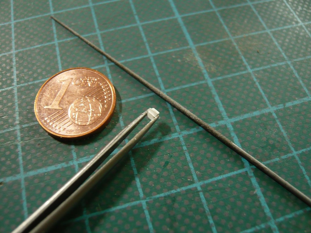 And since the test fitting of the bow on the Cable Tray looked good, 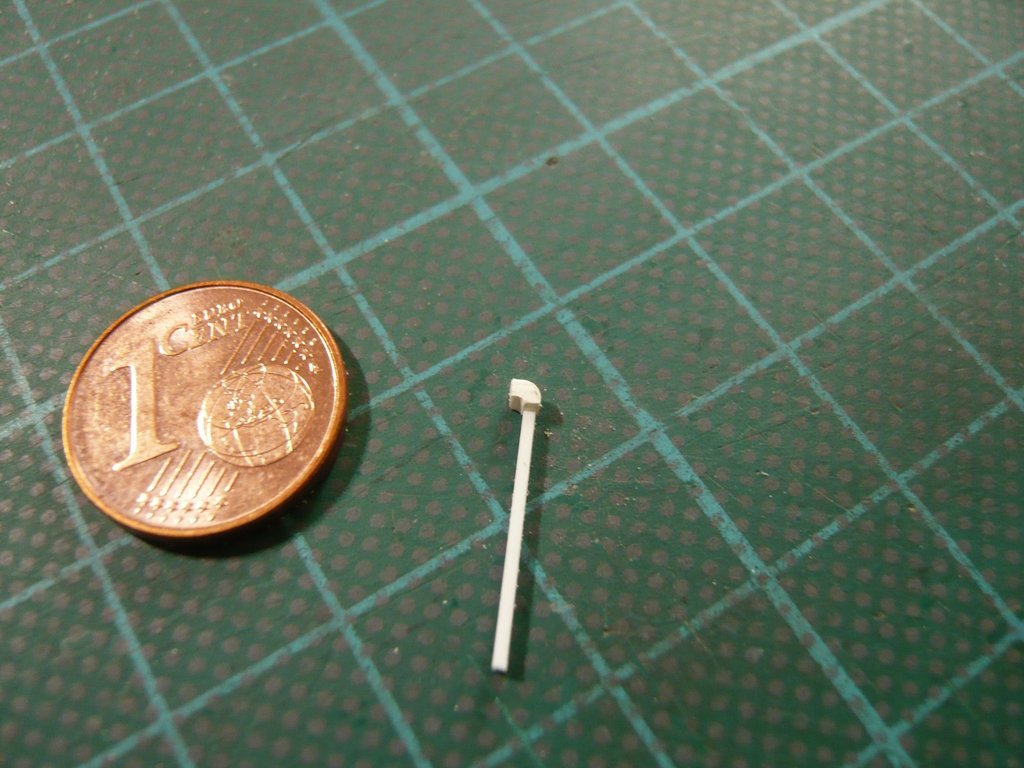 I then glued the bow carefully, 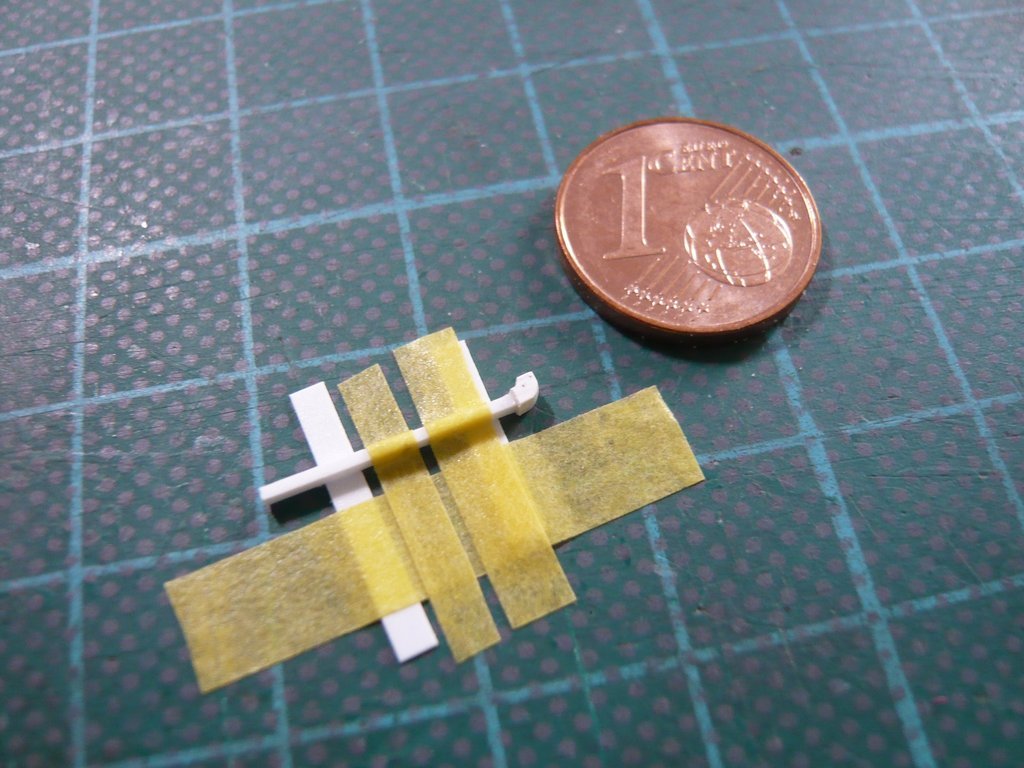 and something aligned yet, which resulted in a good fit of the bow. 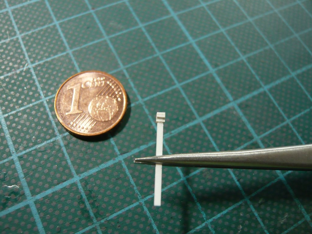 Then I've cut the Middle plate (part 3) out of a Rectangular profile 1,0 mm x 1,5 mm x 2 mm, 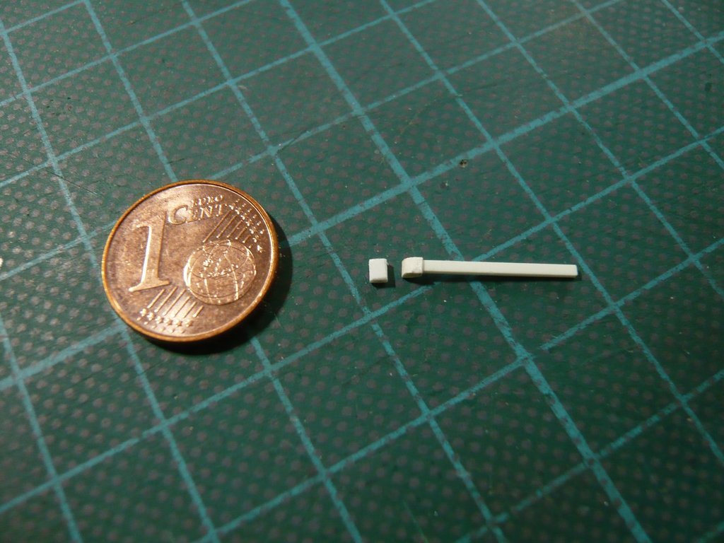 and glued it onto the bow. 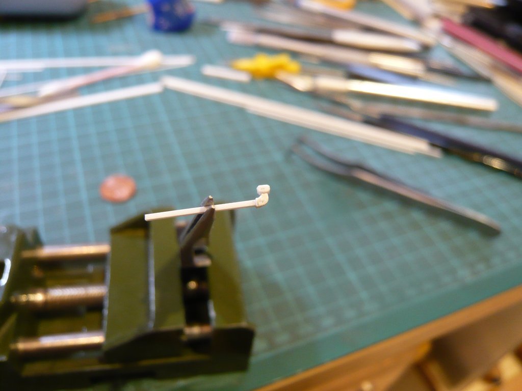 And after the successful fitting I was able to catch my breath,  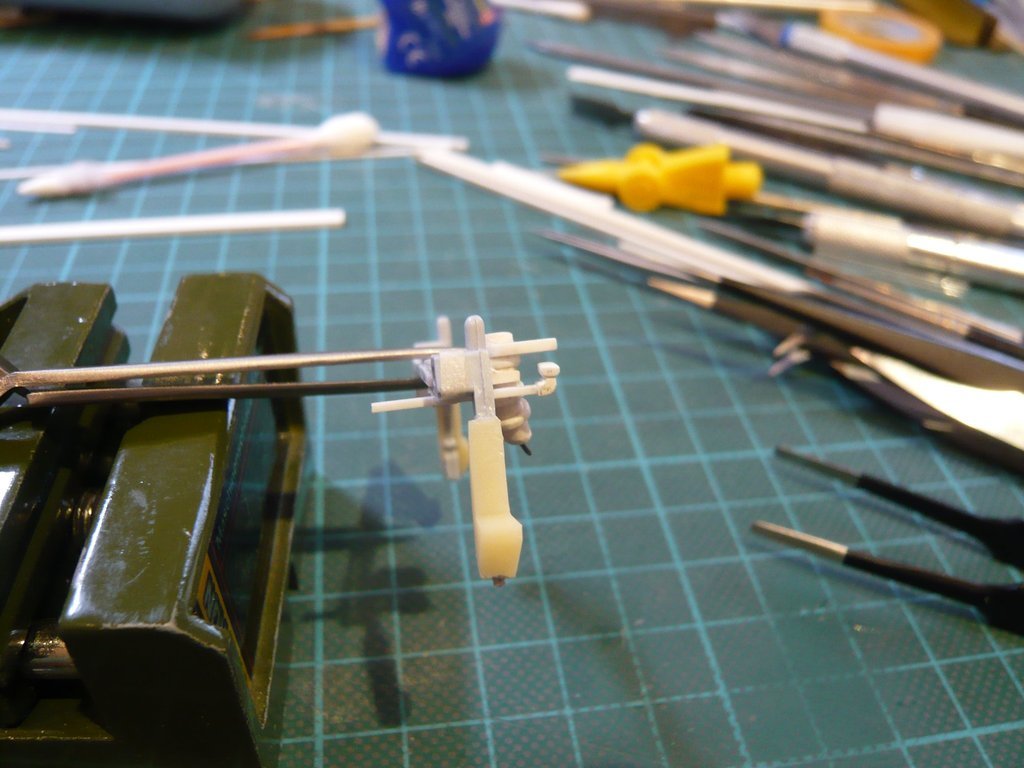 because this transition fits quite well and there is still enough space for the oblique transition to the Umbilical plate (parts 4/5). 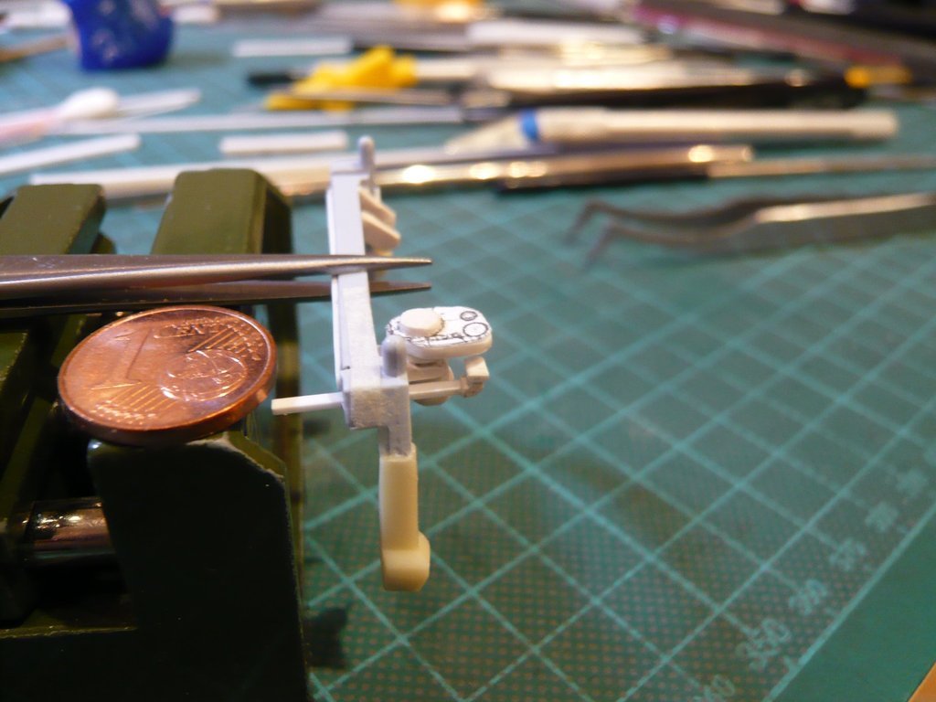 And with this intermediate result I can be quite happy.
__________________
Greetings from Germany Manfred Under construction: Launch Pad 39A with Challenger STS-6 (1:144)
|
|
#1995
08-27-2019, 07:22 AM
|
||||
|
||||
|
Hello friends,
here's an image with the three ports under the LH2 Umbilical Plate that I have to set my sights on.  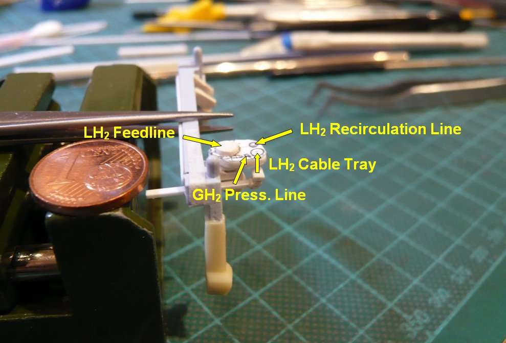 The diameter of the GH2/GO2 Pressurization Lines is 2'', accordingly Ø 0,35 mm at 1:144, and the diameter of the LH2 Recirculation Line is 4'' (Ø 0,7 mm). By comparison, the diameter of the LH2/LO2 Feedlines is 17" (Ø 3 mm). At the transition of the GH2 Press. Line is still missing the oblique transition (Parts 4/5) to the Umbilical Plate, which one can see in this photo of the ET-118 (STS-115), 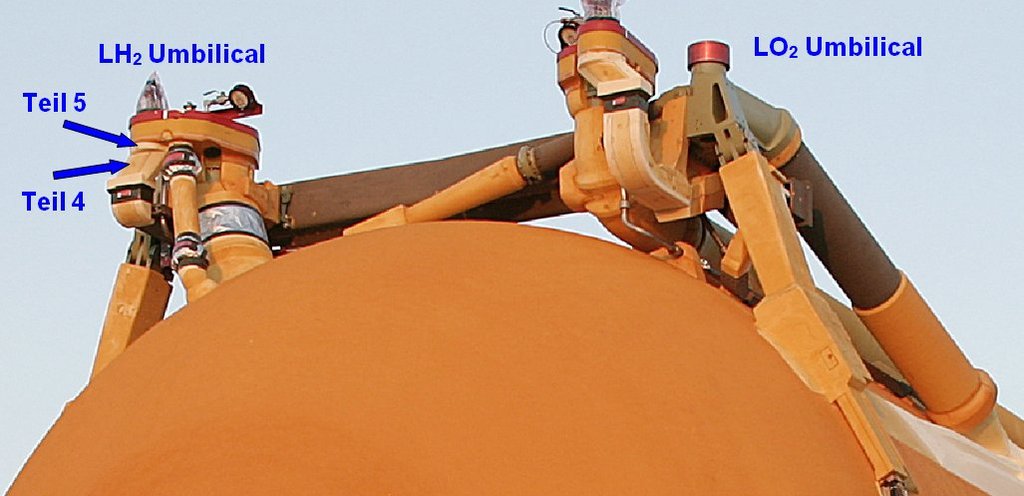 Source: NASA which should follow now. This is a small disc Ø 2 mm x 0,3 mm for Part 5, and the slant for Part 4 is cut of an Evergreen Strip (1 mm x 1,5 mm). 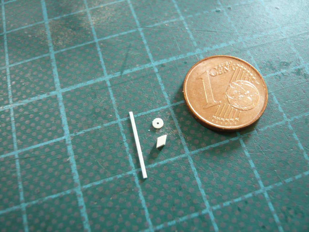 First of all, I wanted to reinforce and file the slant by side-glued Strips 0,25 mm x 0,7 mm, as the true part widened in a funnel shape towards the top, as one can see on this image, but which would be overkill because of the "size" (see above), which is why I decided not to.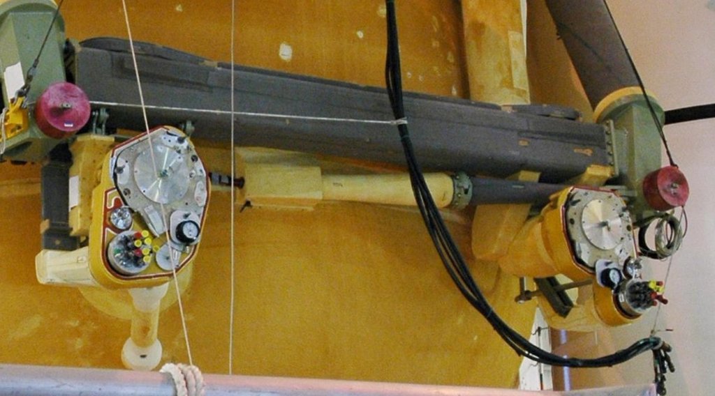 Source: NASA But the test fitting looks quite good, I think. 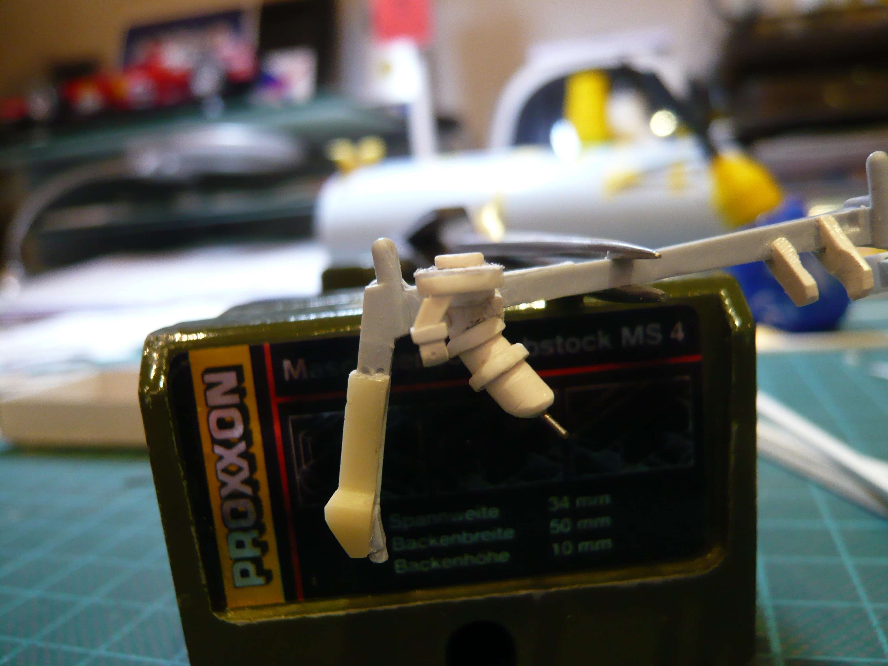 When glueing such tiny parts, it depends on a precise fit, which is why you have to position them exactly and unshakeably before, what I have done here this way. 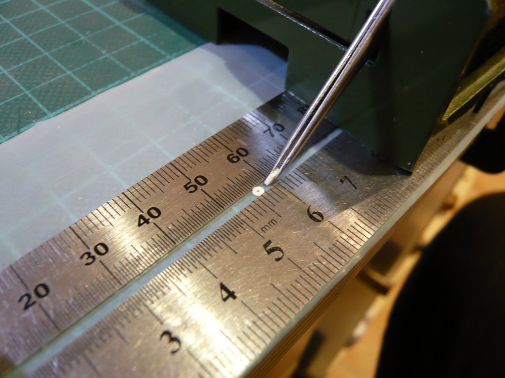 So that the parts do not grow beyond the clear height of the transition (3 mm) due to the bonding, which would happen with normal Revell adhesive,  I've glued them with MEK , which is why I've used a Teflon film, so that nothing sticks to the cutting mat. I've glued them with MEK , which is why I've used a Teflon film, so that nothing sticks to the cutting mat.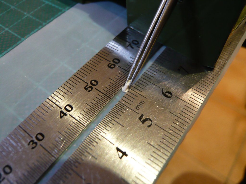 And this is the result, 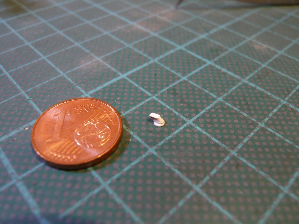 and this slant could now be glued to the Cable Tray bow, which was again a tricky business. 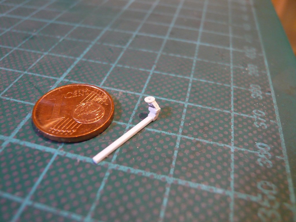 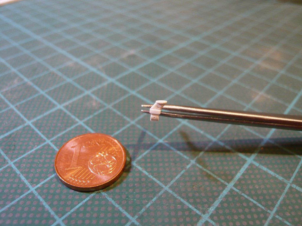 Well, and during the tricky test fitting of this now complete LH2 Cable Tray, the mishap happened to me as the part slipped out of the tweezers and fell to the floor, whereby unfortunately, the painstaking glued slant is broken off ...  ... ...  So that this does not happen again after the repair, I've glued the plate with MEK onto the underside of the Umbilical Plate and centered it in place with a needle. 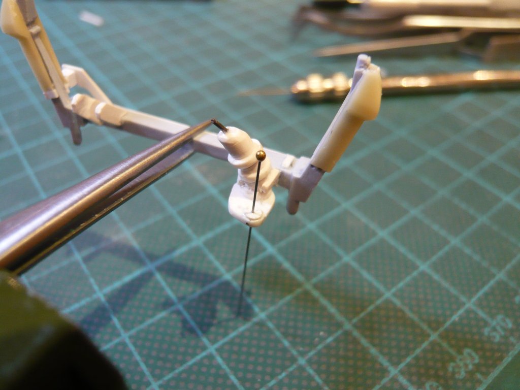 And in this position, I then laid on the 'patched' Cable Tray carefully and glued onto the Crossbeam and under the Umbilical Plate. 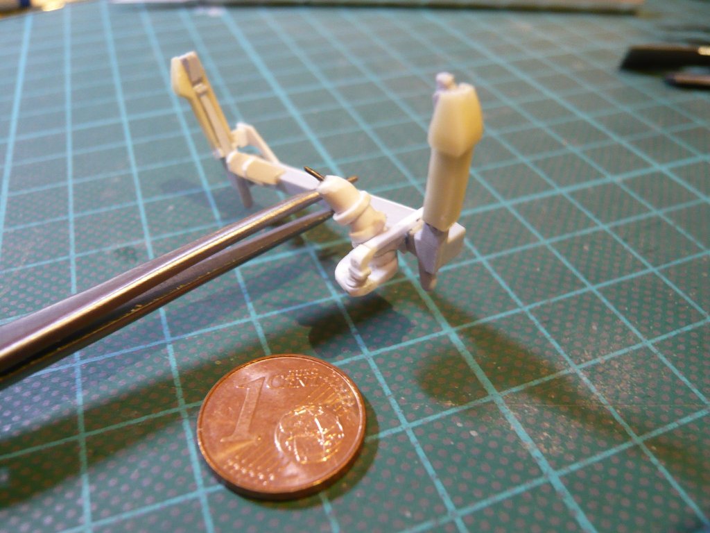 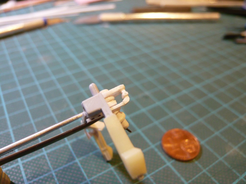
__________________
Greetings from Germany Manfred Under construction: Launch Pad 39A with Challenger STS-6 (1:144)
|
|
#1996
08-27-2019, 07:23 AM
|
||||
|
||||
 And so it looks like on the front of the Crossbeam, where I still have to scratch the the connection with the horizontal Cable Tray, 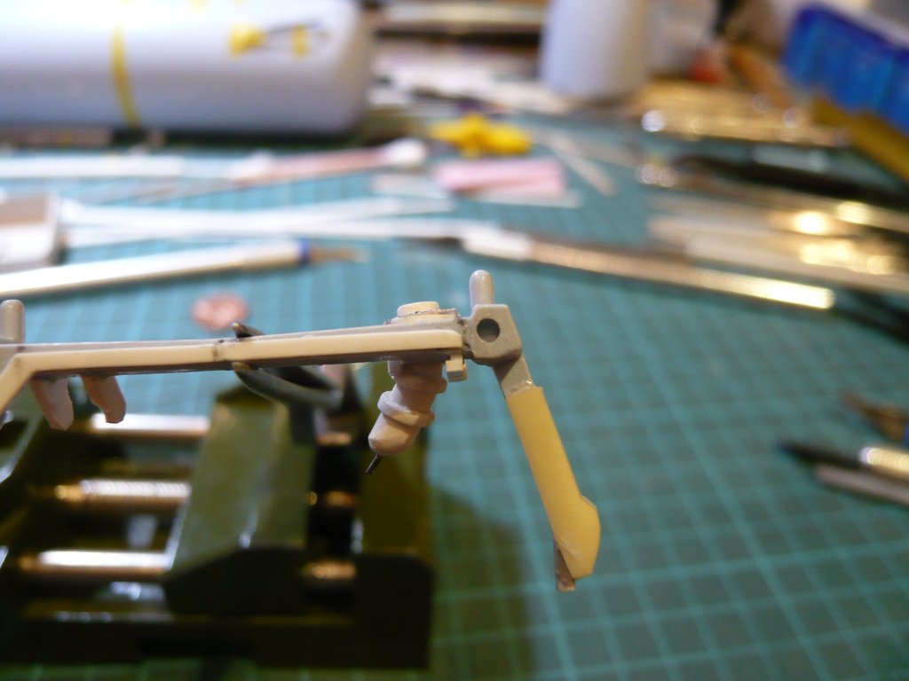 for which I glue first suitable strips in the gap, what from subsequently the lower bow will be sanded.
__________________
Greetings from Germany Manfred Under construction: Launch Pad 39A with Challenger STS-6 (1:144)
|
|
#1997
08-28-2019, 02:48 PM
|
||||
|
||||
|
Hello everybody,
sorry, but these images to the scratching the Cable Tray Bow have fallen by the wayside somewhere, so I want to add them here, which is done quickly. With these two strips I've filled the gap, 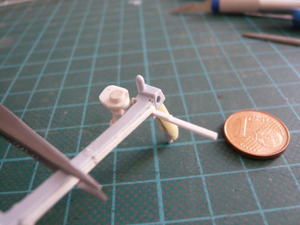 then the supernatant was cut off with the Cutter chisel, 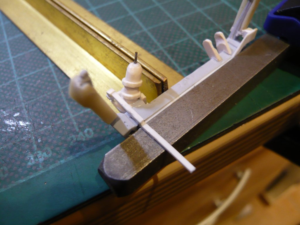 and thereafter the rounding of the bow was gently sanded. 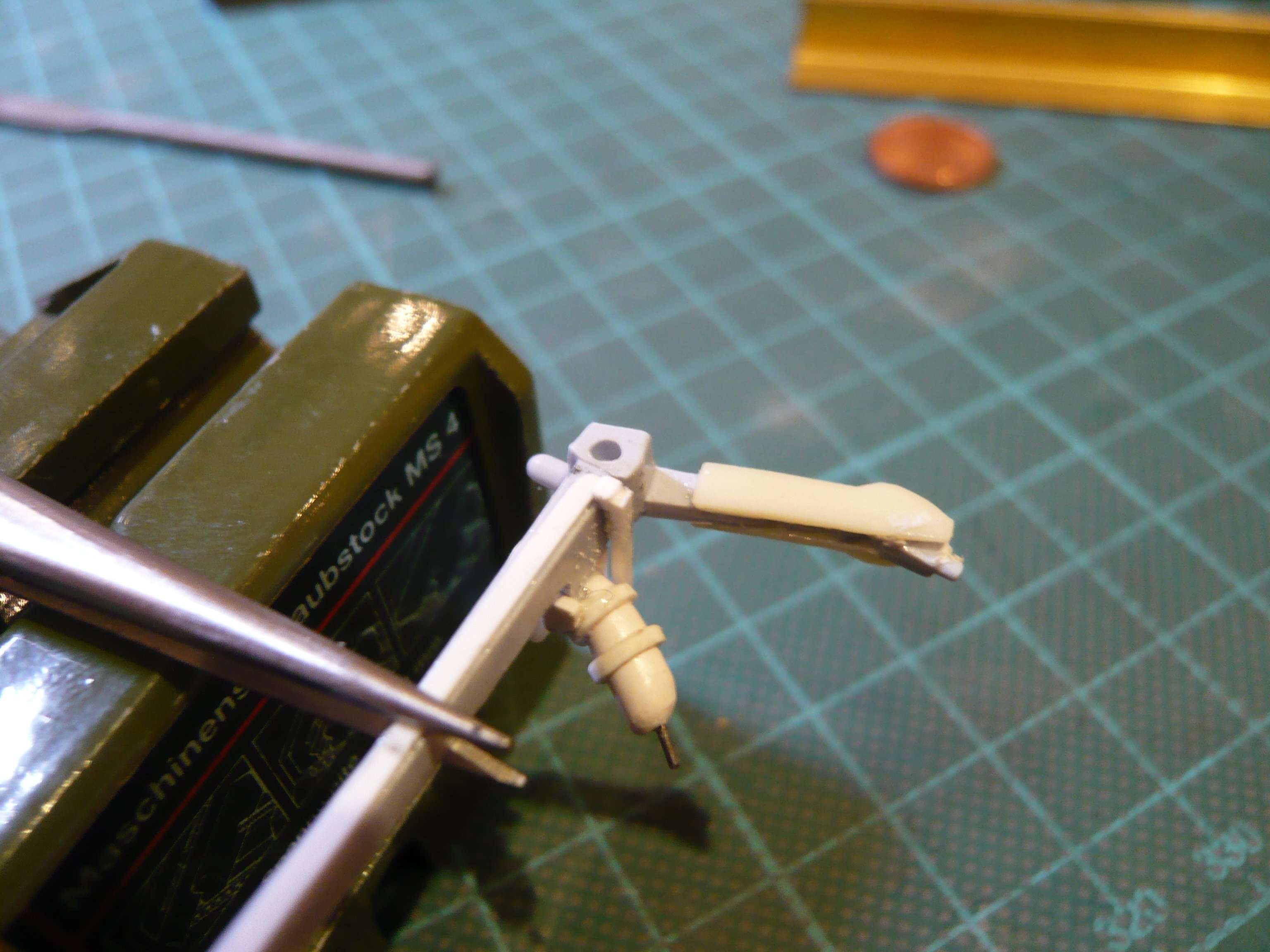 And that was it already! 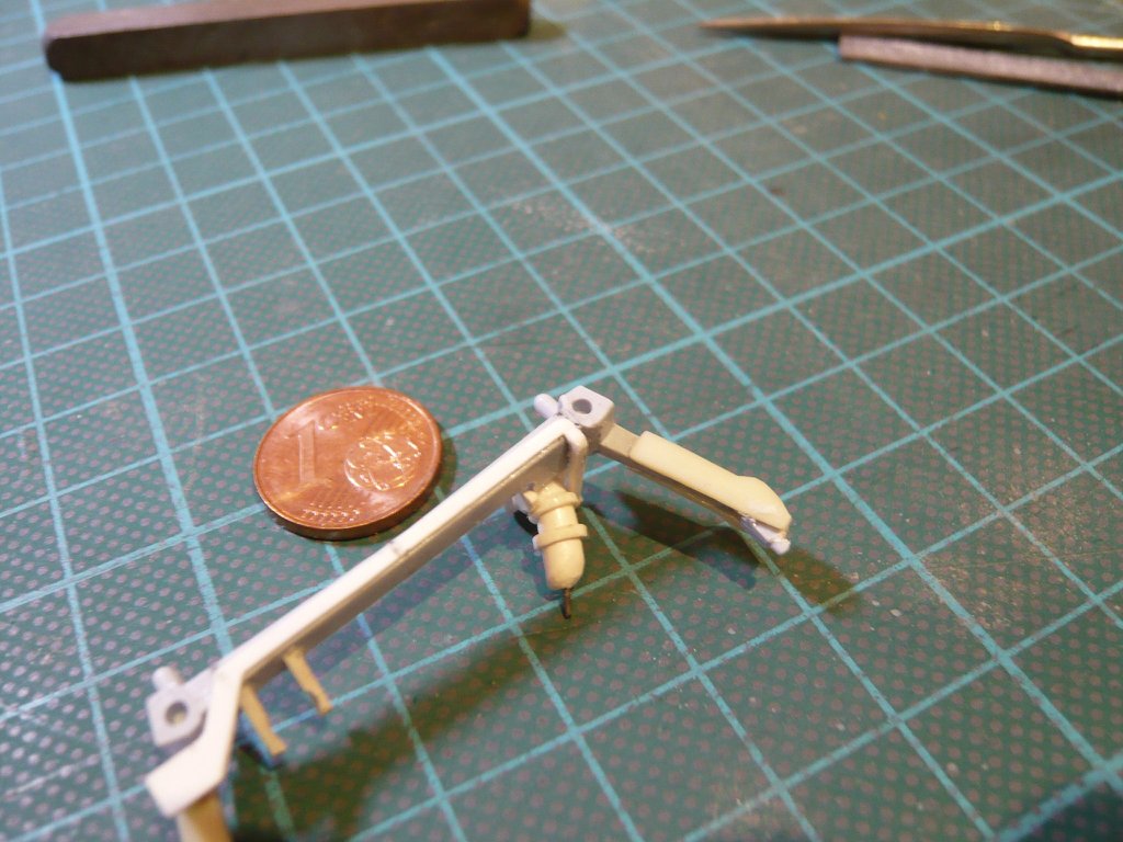 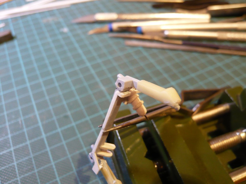 And now to the already announced GH2 Press. Line incl. its TPS cladding, which runs under the leading edge of the Crossbeam, what one can see on this photo of the ET-121 (STS-114) especially well in the zoom,  Source: NASA and also here on this photo. 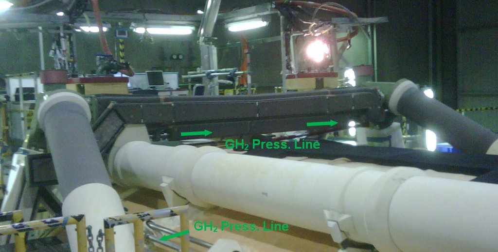 Source: forum.nasaspaceflight.com (DDG40) On the next photo (left) one can see the end of the TPS cladding with the exit of the Press. Line, whose bottom is rounded. Furthermore, one can see that the Cable Tray initially opens into a flat wider distributor, from whose side still a separate Cable Tray branches off into the Vertical strut in which the cables are routed to the ET/SRB Attachment, as one could already see on the LO2 Side on the opened Vertical strut. (s. Reply #1954). On the right image one can see the end of this flat distributor as well as the separate branch in the vertical strut from a different perspective. The only pity is that the slant transition of the Cable Tray to the Umbilical Plate is covered by this cuff. 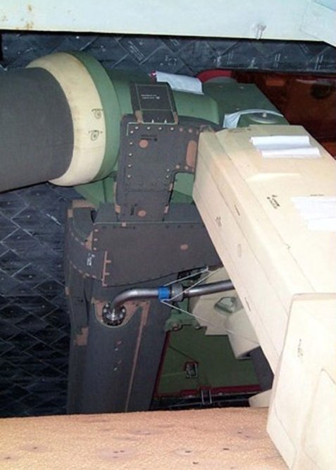 Source: georgesrockets.com (George Gassaway) 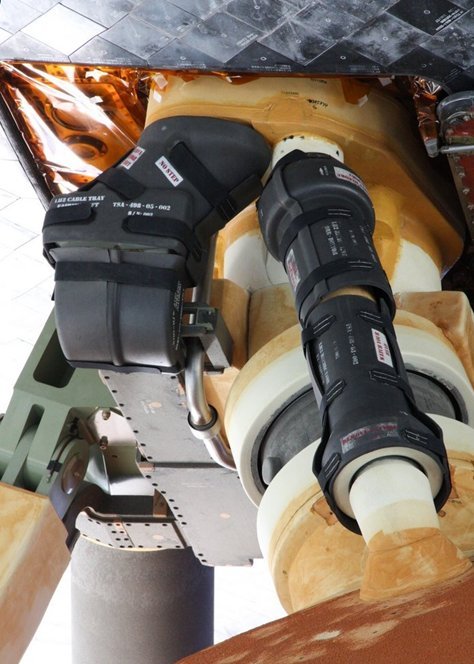 Source: NASA For those who love detailing, on this matching photo of Scott Phillips one can see this branch-transition with cables laid open. 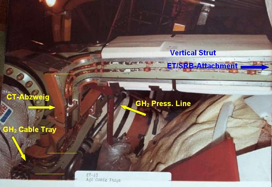 Source: Scott Phillips On the following drawing, the arrangement can be seen at this point in cross section. And as one can furthermore see the previously installed Cable Tray is still attached with two holders to the outer LH2 Feedline Bracket, 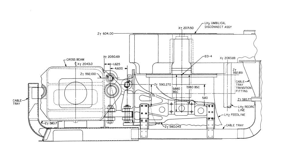 Source: System Definition Handbook SLWT, Vol. II (Lockheed Martin) what is also nice to see in this photo and is still on my To-do list ...  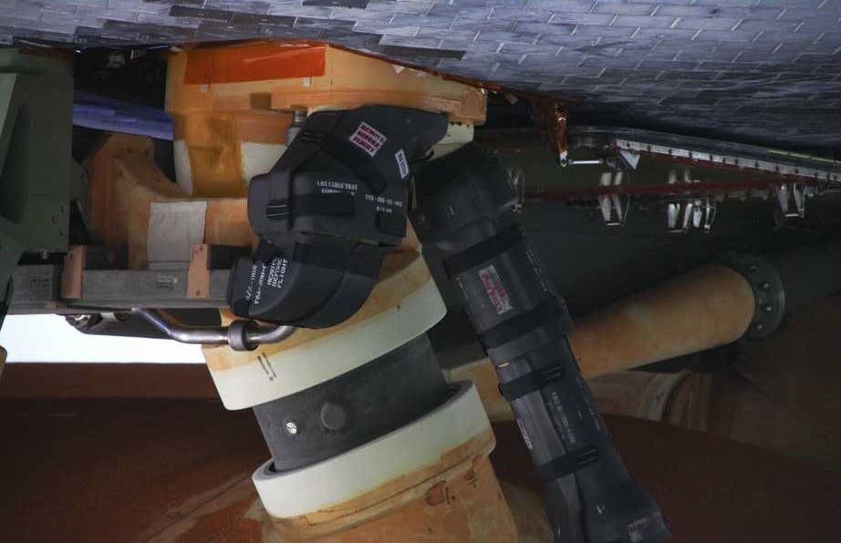 Source: NASA And now to the TPS cladding of the GH2 Press. Line, for which I've glued an Evergreen Strip (0,25 mm x 1,5 mm) with a Semi-circular profile (0,65 mm x 1,5 mm), Which I've drilled off on both ends for the 2'' Press. Line with Ø 0,4 mm, for which I use a German silver round profile (Ø 0,4 mm). 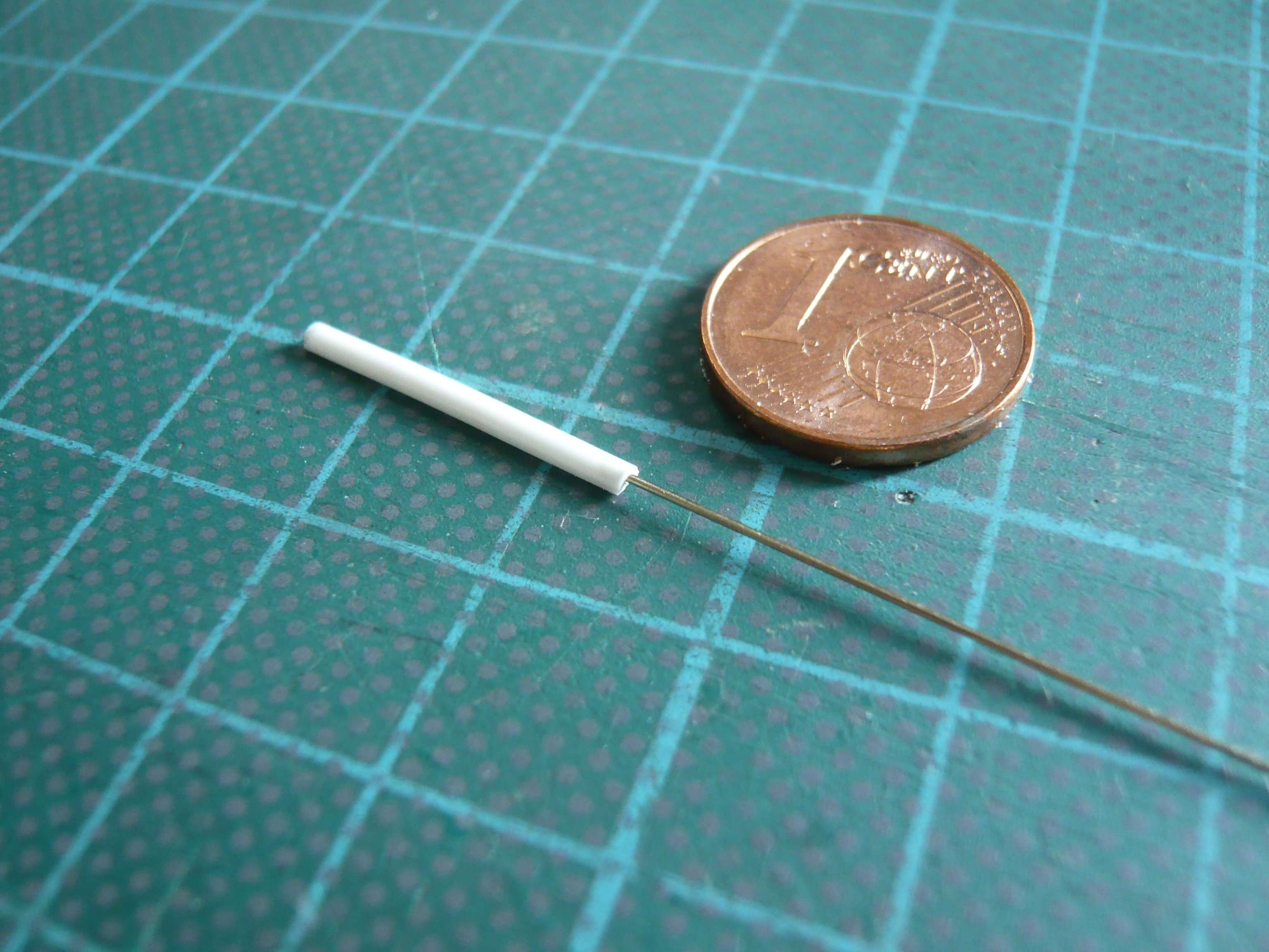
Last edited by spacerunner; 08-28-2019 at 04:59 PM.
|
|
#1999
08-28-2019, 03:31 PM
|
||||
|
||||
|
Hi Jesset,
sorry, but I don't know what your problem is,  can you say it in English? can you say it in English? 
__________________
Greetings from Germany Manfred Under construction: Launch Pad 39A with Challenger STS-6 (1:144)
|
|
#2000
08-28-2019, 03:41 PM
|
||||
|
||||
|
Quote:
__________________
"Rock is Dead, Long Live Paper and Scissors" International Paper Model Convention Blog http://paperdakar.blogspot.com/ "The weak point of the modern car is the squidgy organic bit behind the wheel." Jeremy Clarkson, Top Gear's Race to Oslo
|
 |
| Thread Tools | |
| Display Modes | |
|
|


 Linear Mode

