


|
|
|
#2081
 03-24-2020, 08:17 PM
|
|||
|
|||
|
Hello again Manfred. I really like the look of your razor saw. It appears that it would provide good support for the blade? Is it a favorite of yours?
I have learned to be happy with my Plum Garden DIY Mini Hand Saw Model Craft set,DIY Razor Saw tool Kit with Multifunction Craft Blades https://www.amazon.com/dp/B01NCW6N6G..._T3REEbQ9KM3GP But I’m always open to a new tool.
__________________
Happy Crafting - Scot On the Bench: Planck and Hershcel 
|
|
#2082
03-25-2020, 11:06 AM
|
||||
|
||||
|
Hello sreinmann,
this is a CMK saw blade-holder with a saw blade H1000 with a coarser and a finer side by CMK Kits ESHOP, which one can find here: https://www.modellparadies.com/saege...BoC8uIQAvD_BwE  This mini saw has the advantage that the blade sits in a stable plastic holder and is very thin with 0.1 mm, which guarantees very fine cuts.  The only disadvantage is that one can only achieve cutting depths of up to 7 mm due to the holder. Otherwise, I can highly recommend this saw, especially since there are a number of blades with differently fine saw teeth. 
__________________
Greetings from Germany Manfred Under construction: Launch Pad 39A with Challenger STS-6 (1:144)
|
|
#2083
03-26-2020, 01:35 AM
|
||||
|
||||
|
Hello everybody,
and thus to my test bores in order to test whether the minimum depth of approx. 5 - 10 mm could be achieved by hand with an appropriate caution and care.  Since my Dremel is already nearly 10 years old, I wanted to test it once again in the associated drill stand, although I had doubts whether the lowest speed of 10.000 rpm already would be overkill and too risky.  That's why I started by doing some manual tests true to the motto Better safe than sorry!. For this I clamped a Resin strip in my Mini vice and started turning the Dremel-chuck with a drill Ø 1,3 mm in the Dremel-stand with the left hand , while at the same time I've soulfully forced down the lifting rod with my right hand, which was not so easy.  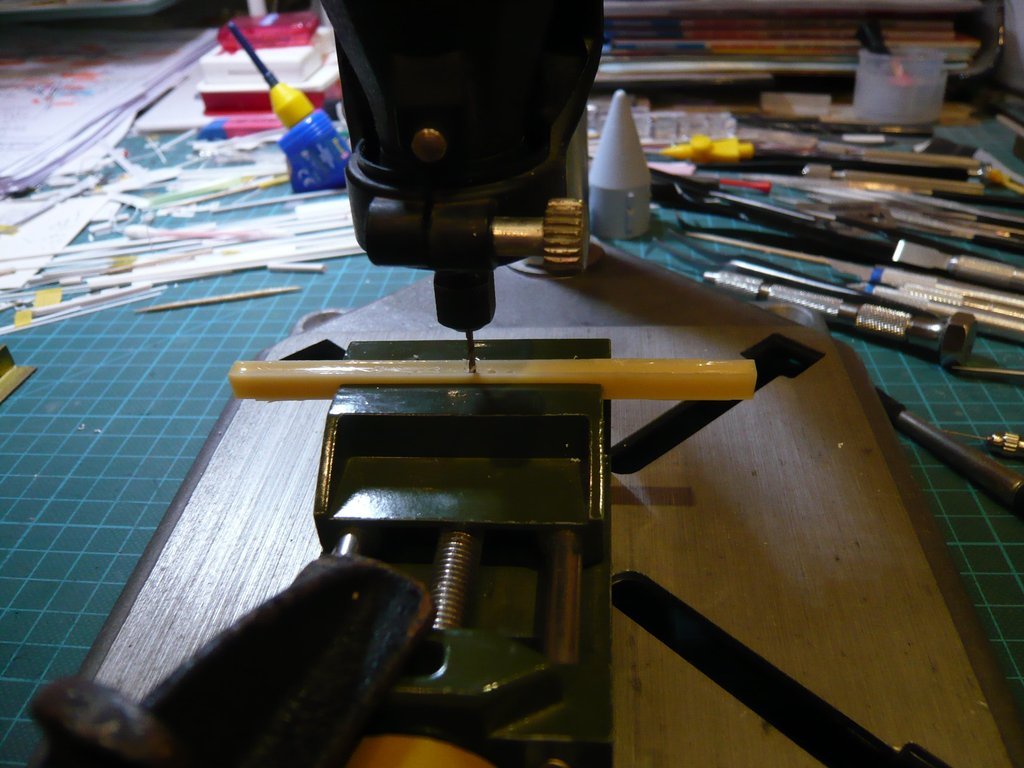 While the orthogonality of the bore in longitudinal direction was acceptable, 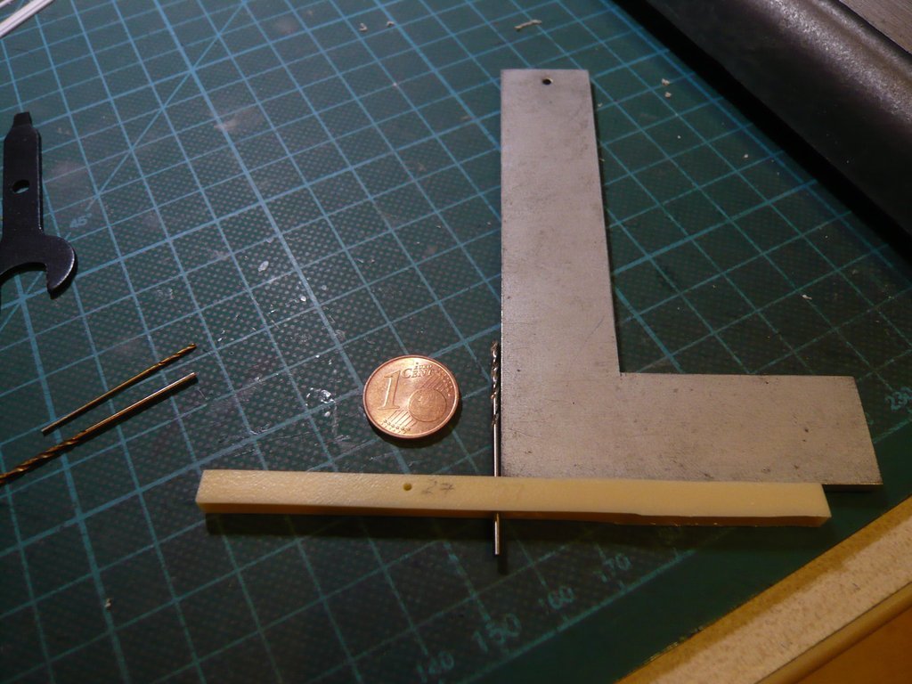 it left something to be desired in the transverse direction, 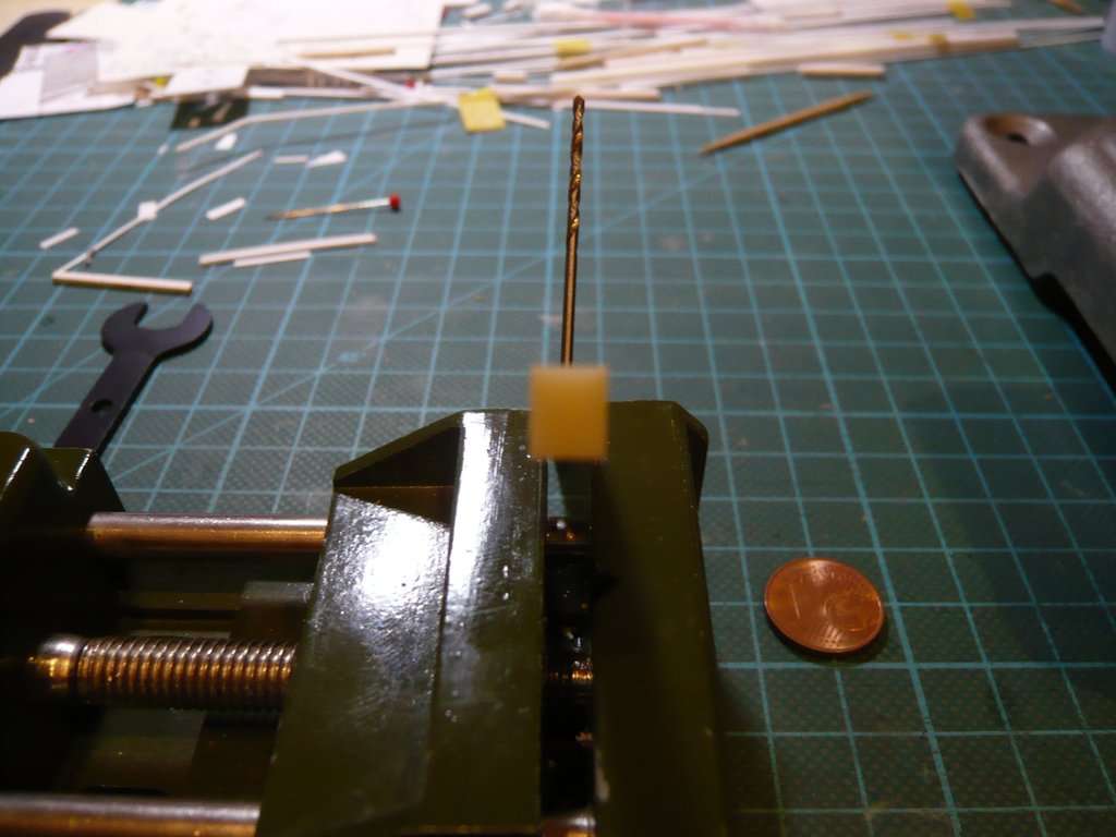 which is why I was not completely convinced of this hand-drilling variant.  Therefore, in a second series of tests with the Dremel in the drill stand I have drilled at the lowest speed (10.000 rpm) in a Chipboard with Ø 1,3 mm, 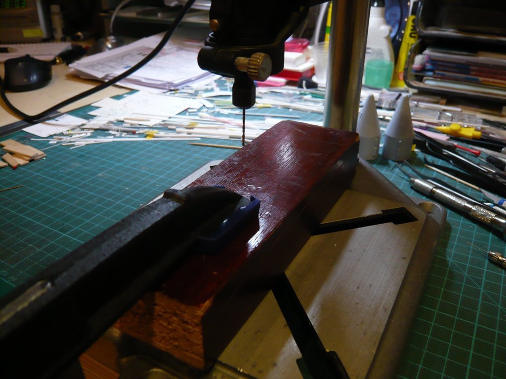 what went smoothly.  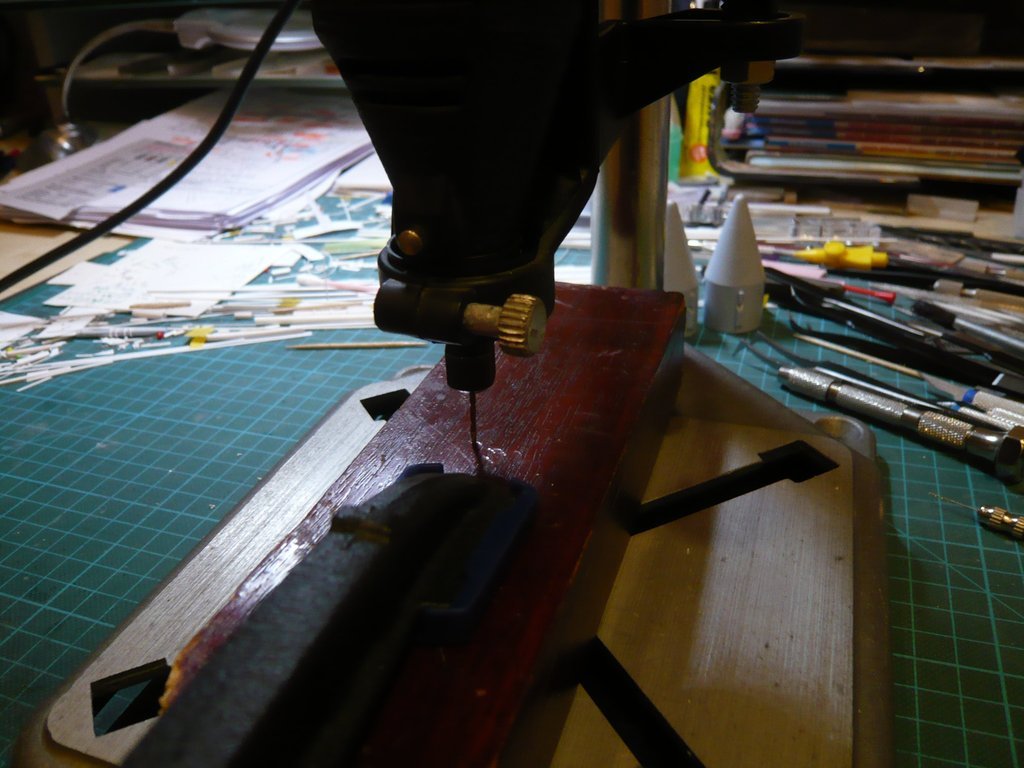 Then I've drilled with Ø 1,4 mm and then took a look at the orthogonality of the bore in the longitudinal and transverse directions, which looked surprisingly good at least over the minimum length.  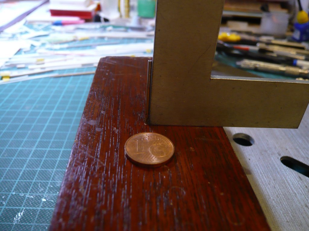 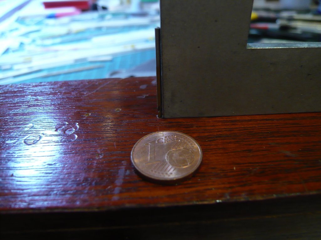 Then I've drilled with the diameter of the SRB support rod (Ø 1,5 mm) and tested again in both directions, whereby the orthogonality was still unchanged good. 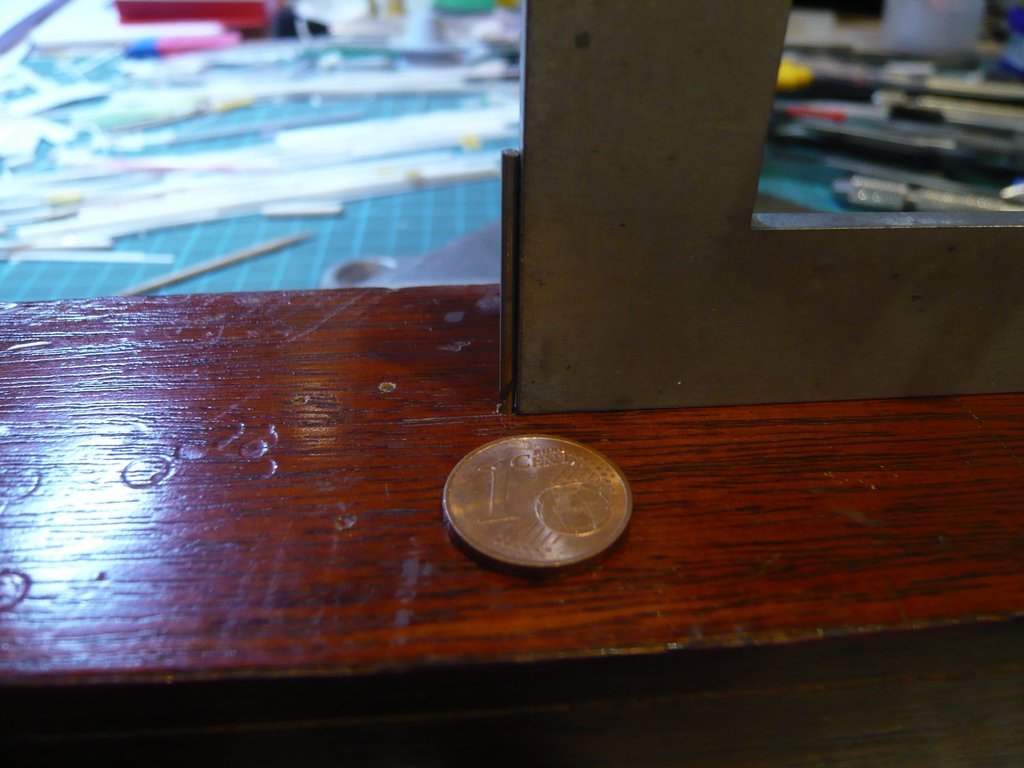 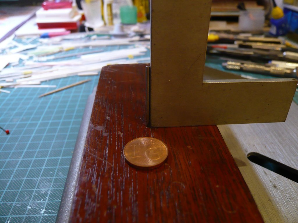 And the support rod also fit well into the bore, which was about 15 mm deep, which should be sufficient for the stable fixation of the boosters in my opinion, whereby I still could then drill a bit deeper with a Mini hand drill.  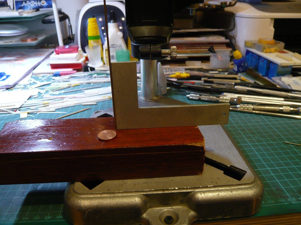 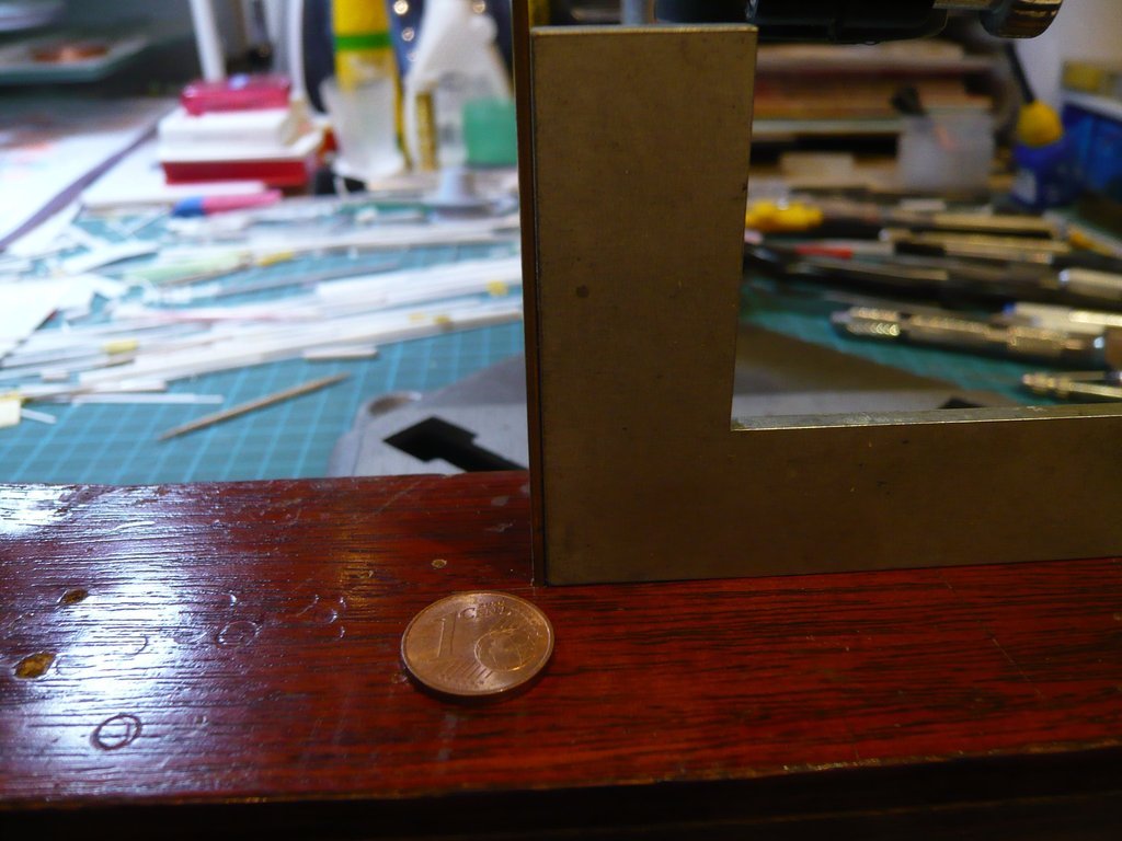 So I could now venture on the bore of the two SRB Forward Skirts from the Newware Kit, whereby in addition to a stable support in a corresponding holder, especially the skirts have to be precisely aligned so that their bores are in line with the support rod.  
__________________
Greetings from Germany Manfred Under construction: Launch Pad 39A with Challenger STS-6 (1:144)
|
|
#2084
03-26-2020, 10:16 AM
|
||||
|
||||
|
Hello everybody,
so far so good. Next, I've determined the position of the base point for the bore of the Support rod, which was not so easy, because it could not be marked in the narrow space, which is why I had to improvise a little bit with masking tapes.  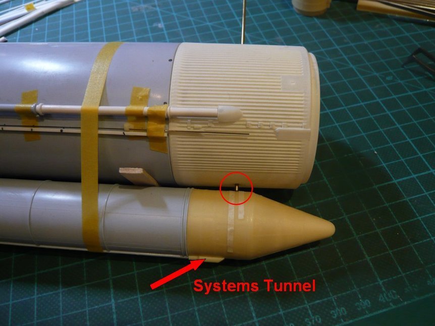 The next problem was the necessary level support of the part as a prerequisite for an exact drilling, which was also not easy due to the disruptive Systems Tunnel at the bottom, which is why an exact clamping in the vice was rather difficult.  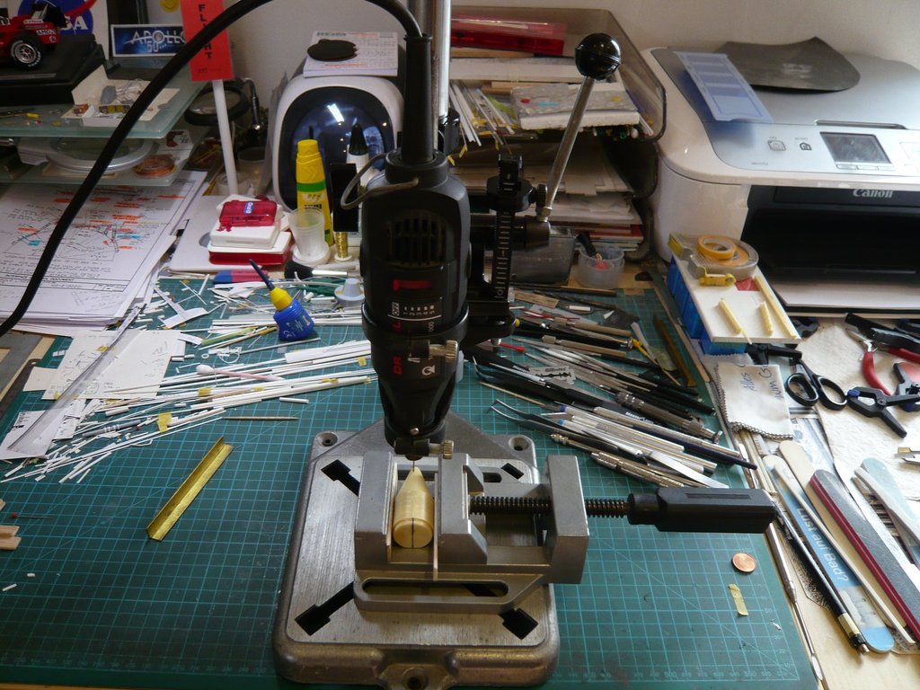 That's why I clamped a brass angle for orientation in the Z-direction, 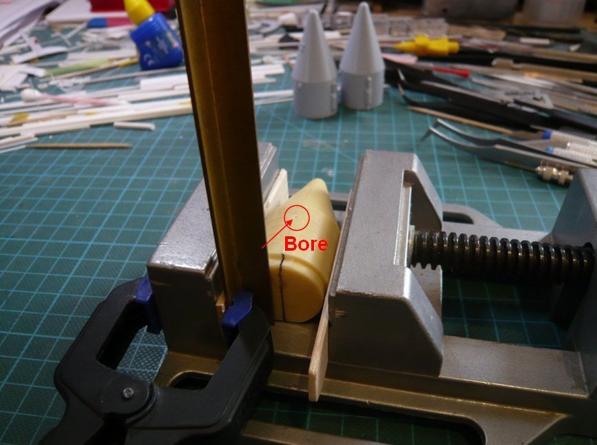 and aligned the center line on the back of the part as good as possible parallelly.  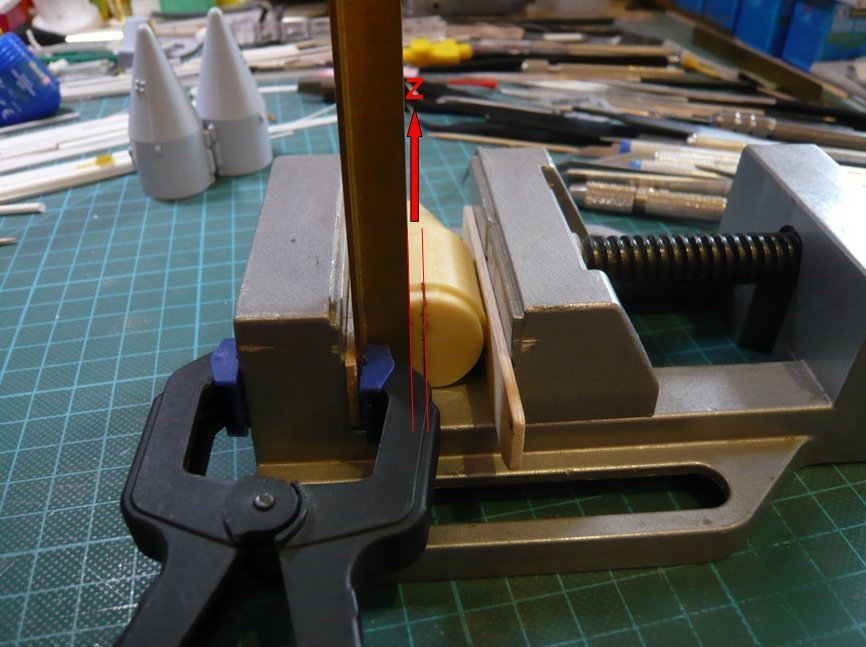 For the alignment in the X-direction I oriented myself on the upper edge of the vice. 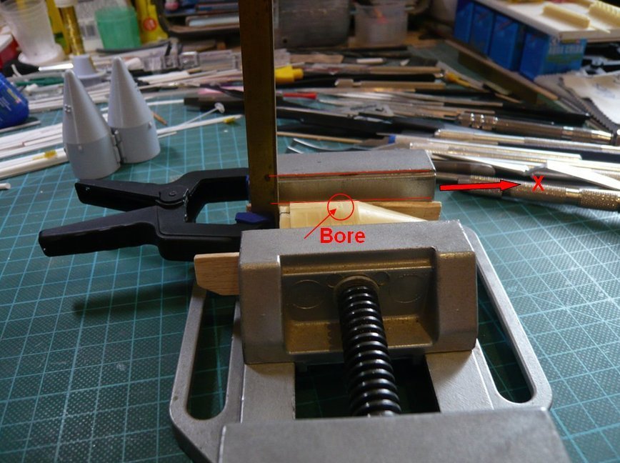 For better orientation here one can see the Orbiter vehicle coordinate system.  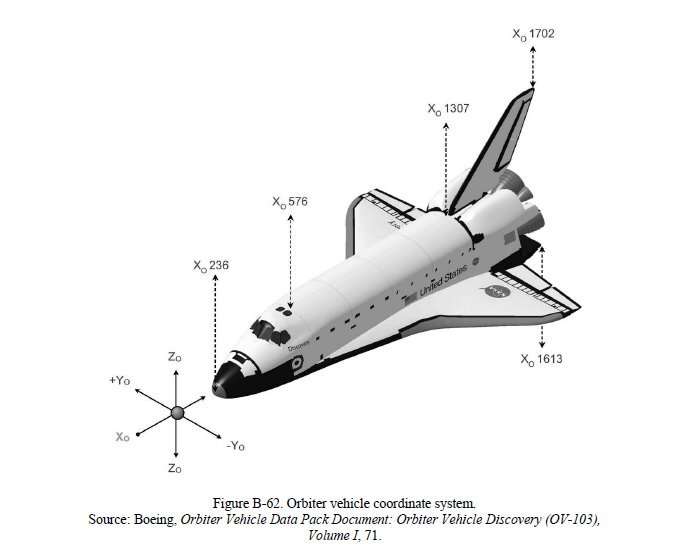 Source: Marshall Space Flight Center, Space Transportation System HEAR No. TX-116 And in this position I will try now drilling the hole, again step by step, carefully pre-drilling with Ø 1,3 mm, and then drilling out with Ø 1,4 mm and Ø 1,5 mm. Hopefully I can do this successfully, so please keep your fingers crossed! 
__________________
Greetings from Germany Manfred Under construction: Launch Pad 39A with Challenger STS-6 (1:144)
|
|
#2085
03-28-2020, 02:06 AM
|
||||
|
||||
|
Hello everybody,
in order to be able to mark the point for the bore a little more precisely, I've dabbed the support rod with marker ink and carefully lowered the booster. When contacting it should leave a small dot of ink precisely where the hole is to be drilled. But it is almost impossible to hit the exact point for the bore, because one cannot align the SRB skirt so precisely by hand onto the Intertank. But this is not necessary either because it is sufficient to mark a short contact line with the rod's ink circumferentially on the Intertank, because the exact point for the bore results at the intersection of this line with the longitudinal engraving on the skirt. That's why I applied this method also still at the right SRB skirt with the tapes, the result of which can be seen here. 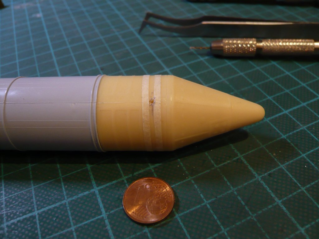 The more precise point is therefore a little bit further ahead.  And therefore: Nothing ventured, nothing gained! - Let's get on with it! Before with drilling it could really come down to business, the vice onto the drill stand was carefully aligned so that the drill came to stand directly over the pre-drilled hole, whereupon this arrangement was then firmly fixed to the table top with a screw clamp. 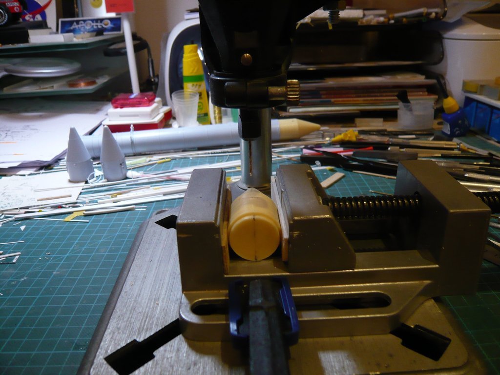 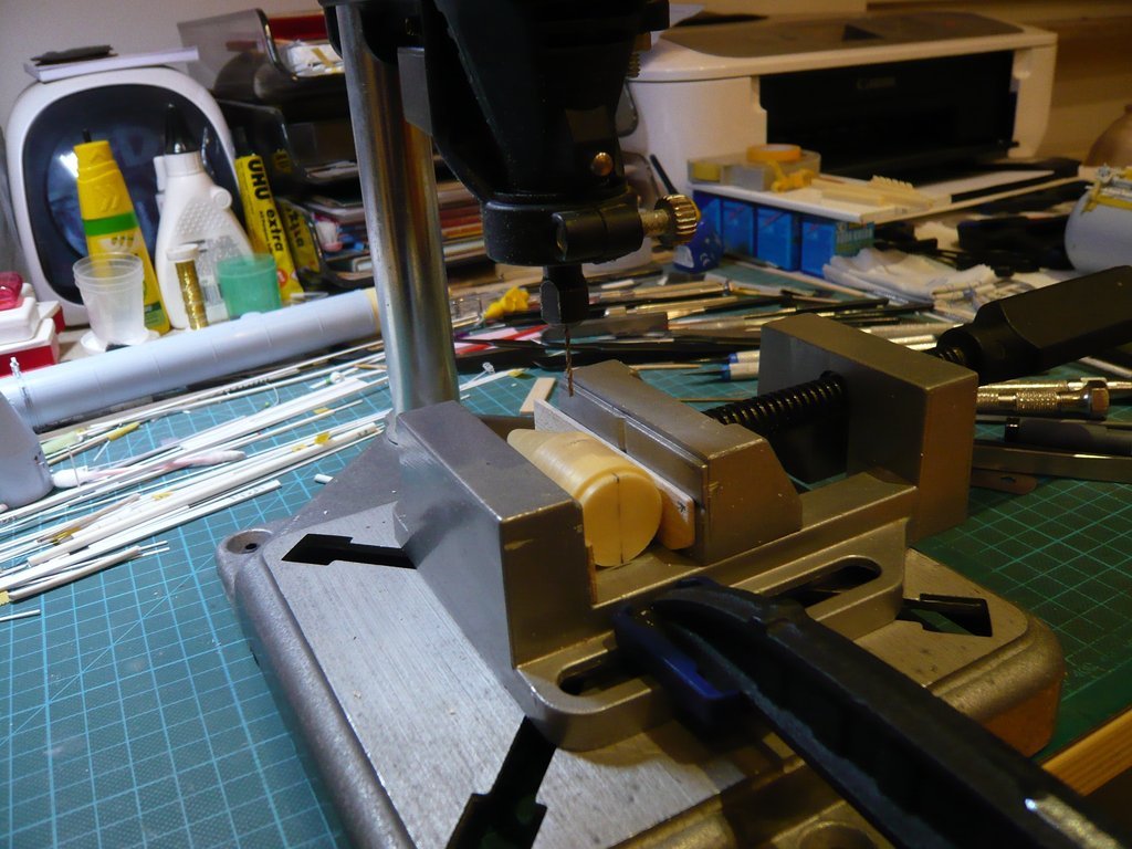 Then, as with the test bores, the holes were drilled step by step, first carefully pre-drilled with Ø 1,3 mm, after which this bore was then drilled out with Ø 1,4 mm and Ø 1,5 mm to a depth approx. of 20 mm. And as the following two images show, the orthogonality was surprisingly good in both directions. 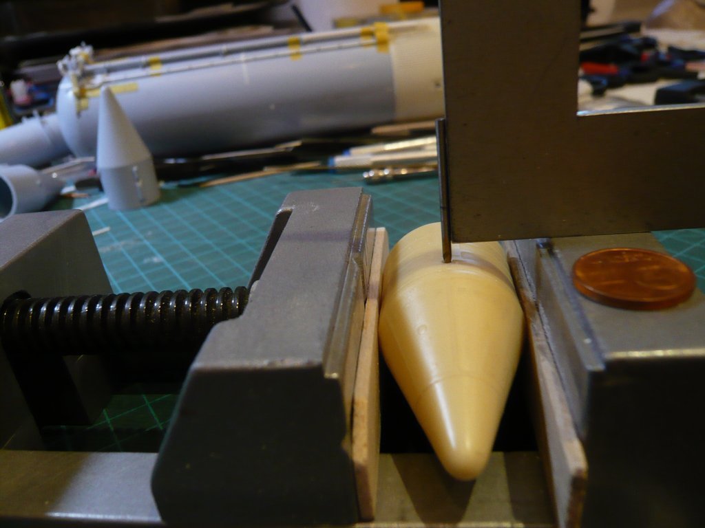 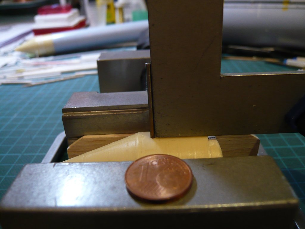 Then the front part was inserted into the booster and with the bore put onto the Support rod in the Intertank, as well as put down with the two rear struts above the openings at the ET's rear, 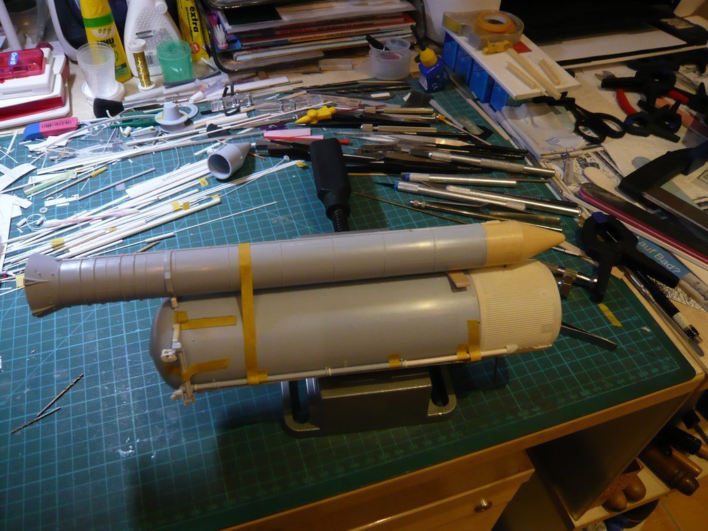 whose feet had to slightly ground until they fit in the openings. 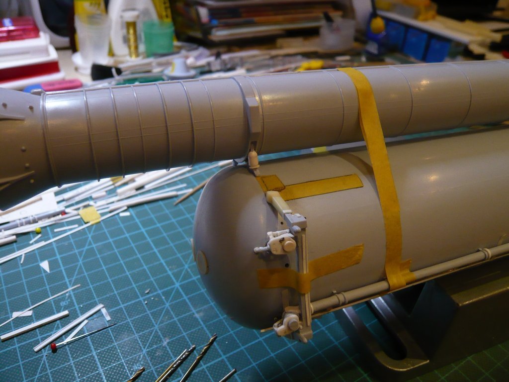 At the front end a Balsa board (2 mm) was inserted as a spacer, 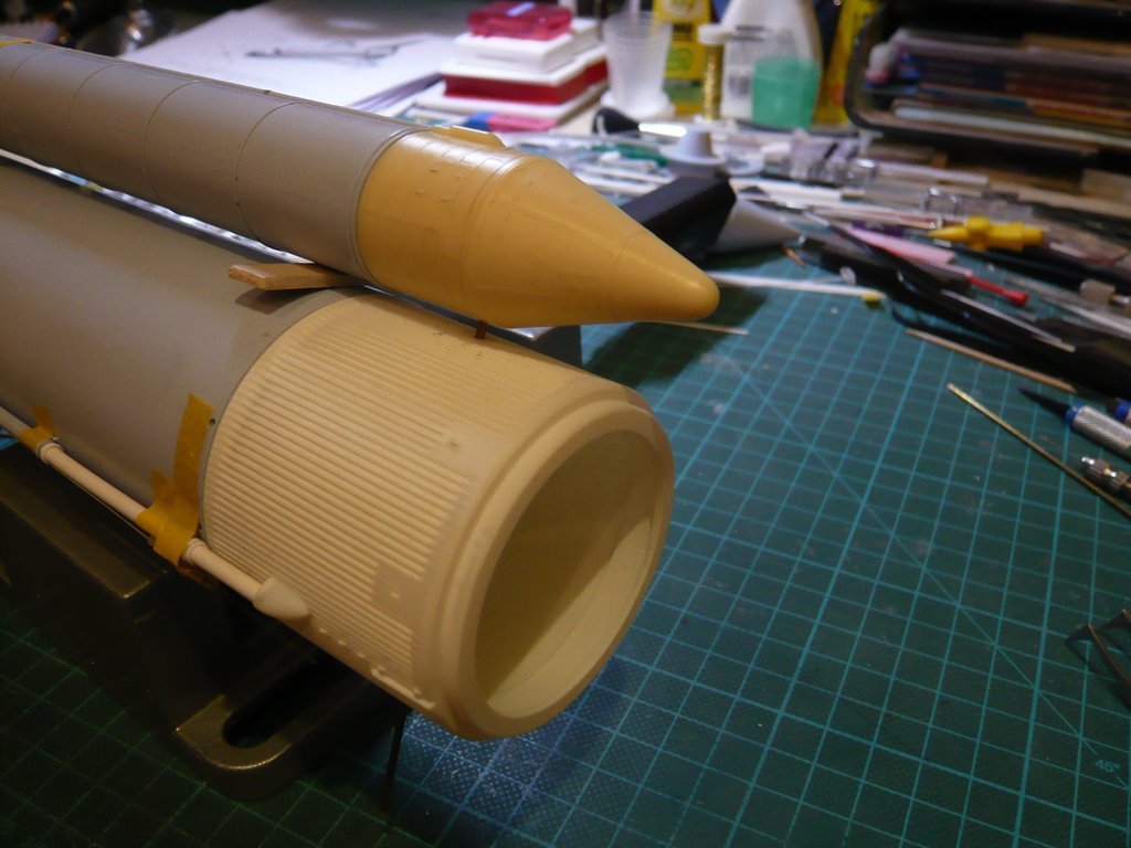 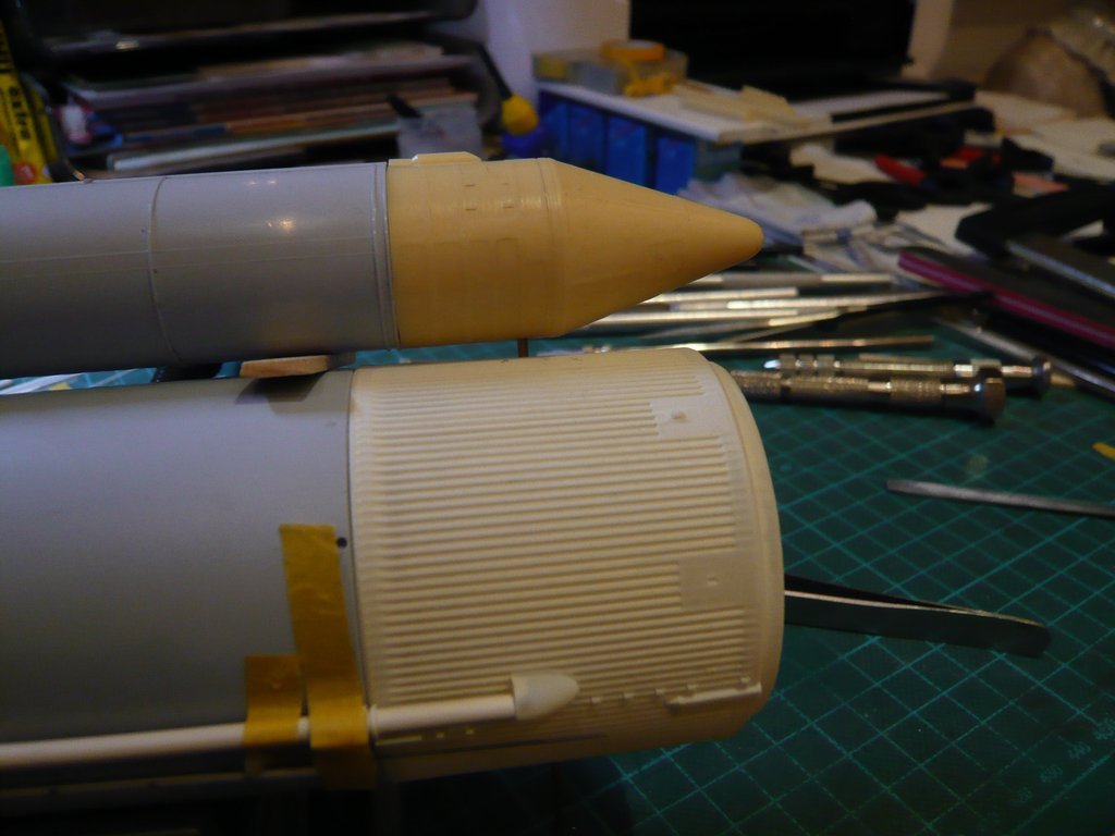 since the already mentioned SRB Thrust Fitting has to be glued directly behind the support bar, which is unfortunately missing at the Newware front parts,  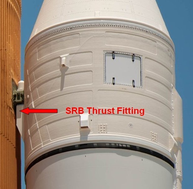 Source: NASA which is why I have to scratch this part.
__________________
Greetings from Germany Manfred Under construction: Launch Pad 39A with Challenger STS-6 (1:144)
|
|
#2086
03-28-2020, 02:11 AM
|
||||
|
||||
|
Hello everybody,
the same drilling procedure I have now carried out with the right SRB front part, which has been similarly good and successful. And so I have now been able to attach both SRBs provisionally at the ET, what fits together quite well and also looks good, in my opinion. 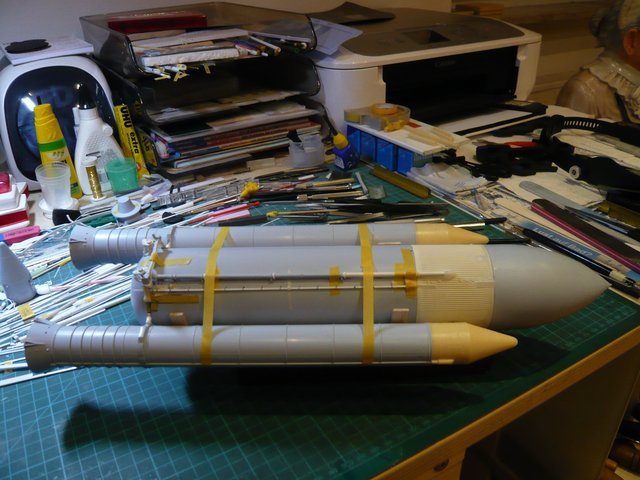 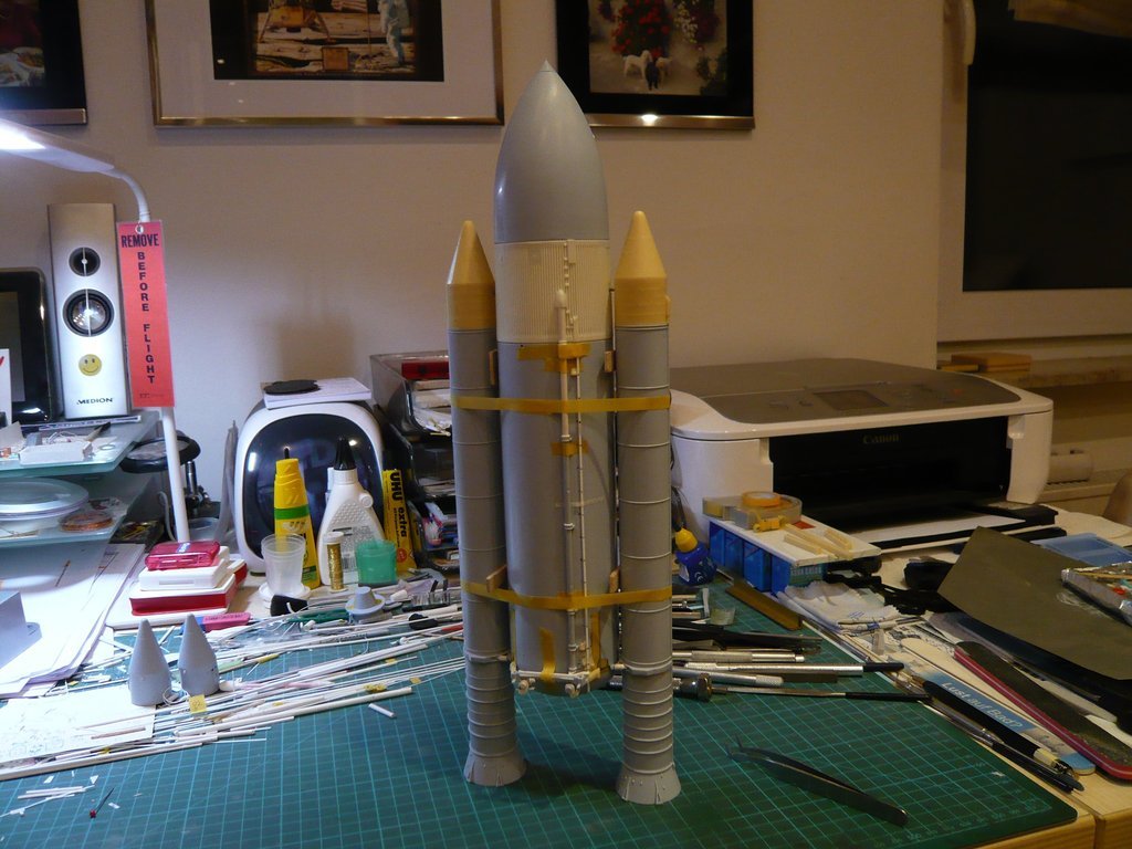 And since there was nothing to be seen of the MLP for a long time, I took it out of the closet and put this ET-SRB-Troika on it. 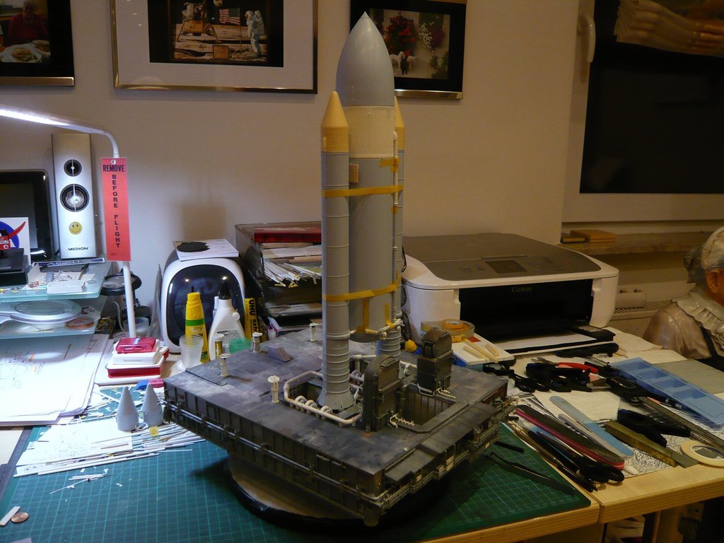 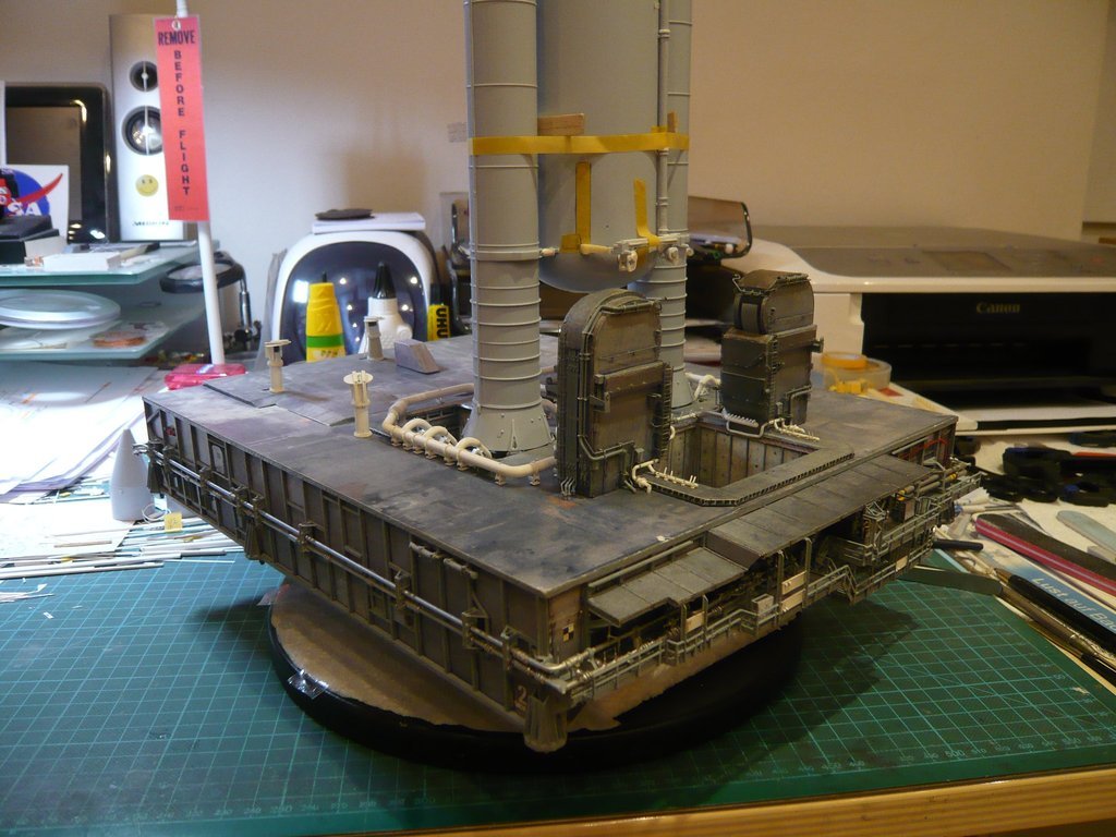 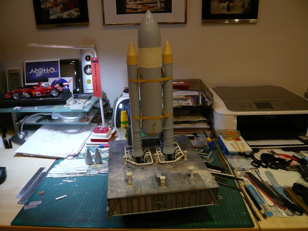 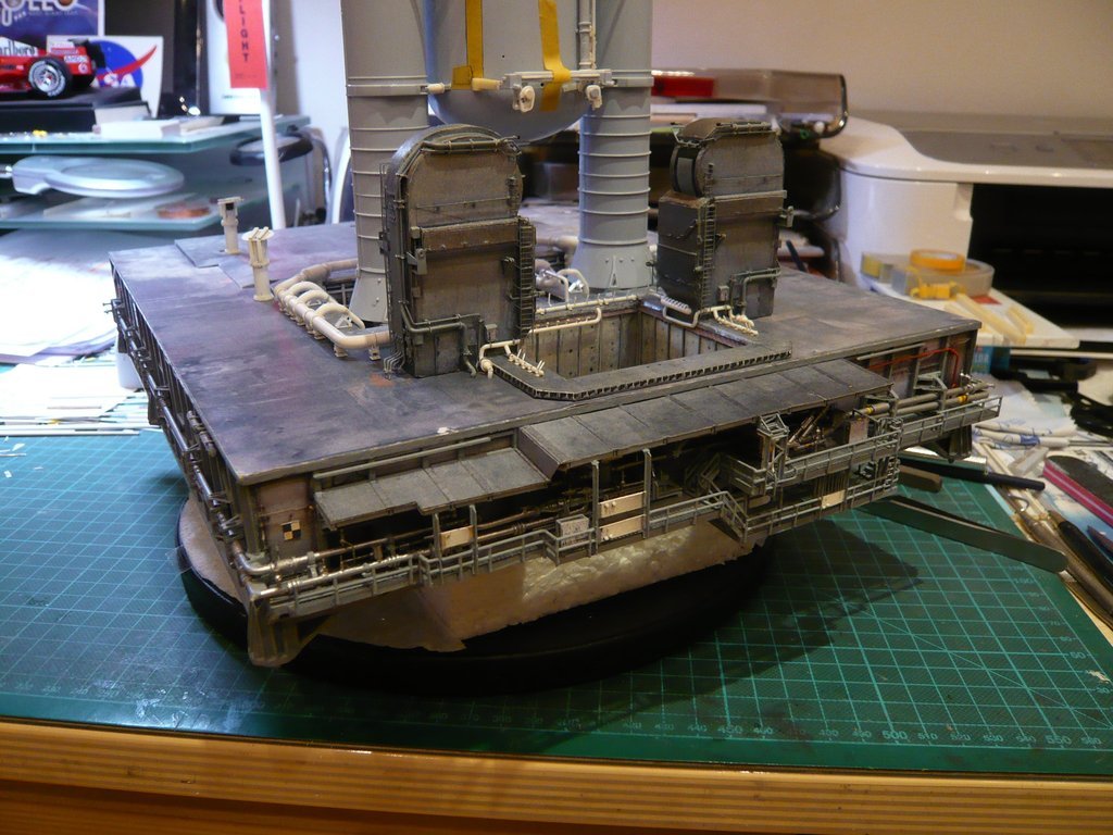 That should it be for today.
__________________
Greetings from Germany Manfred Under construction: Launch Pad 39A with Challenger STS-6 (1:144)
|
|
#2087
03-29-2020, 05:23 AM
|
||||
|
||||
|
Hello friends,
now that my new PC is running, it can finally continue on the Stack-construction site, whereby it specifically concerns the front connection points between the ET and the SRBs, these are the so-called ET/SRB Forward Attach Fittings, one of which was already shown in this picture, whereby the cladding over this green segment is missing. 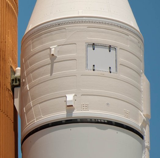 Source: NASA Apparently, this is not just a cladding, because as one can see in this photo of the STS-6 Stack in the final state before the launch of the Challenger, there are two white boxes stacked over one another. Since this image shows the front of the stack facing the orbiter, the question immediately arises as to how this connection assembly may have looked on the back. 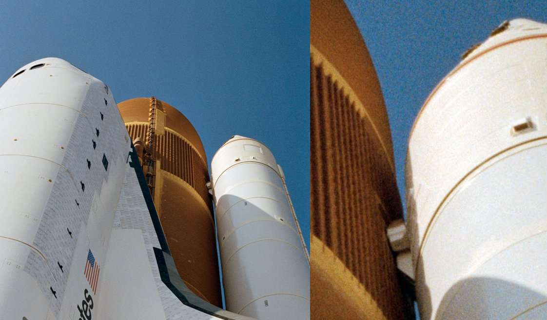 Source: forum.nasaspaceflight.com (woods170) To find out, I had to do a bit more research and have found this photo of the ET-121 after its separation from the Discovery (STS-114), that was the so-called Return To Flight Mission after the Columbia disaster (STS-107). On that one can see on the underside, although a little small, the part of the fitting that belongs to the ET. The rest of the part is therefore on the previously blown away Booster.  Source: NASA The following photo montage shows how the two assemblies of the attachment fit together. 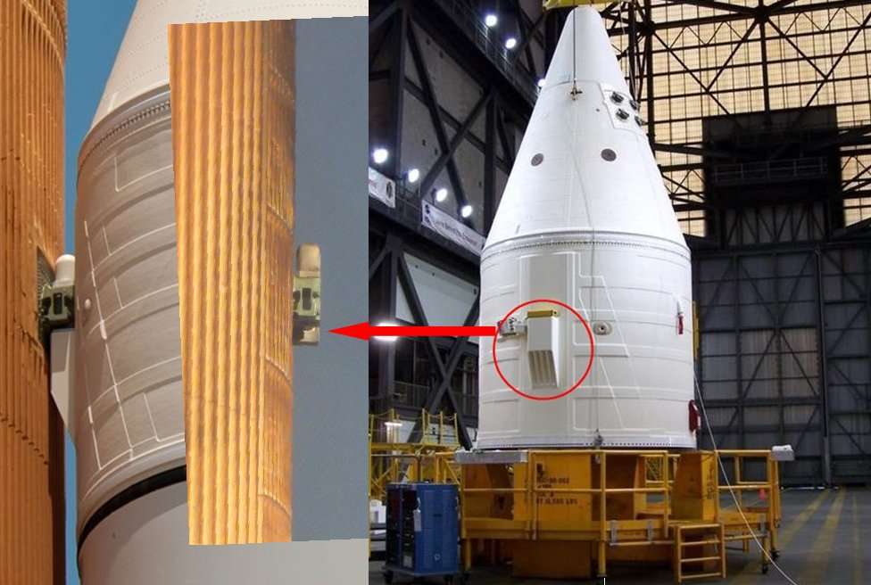 Helpful for my understanding were these drawings of the Attach Fitting, on which the parts belonging to the ET are colored green and those of the SRB are blue, which are connected by the Separation Bolt. 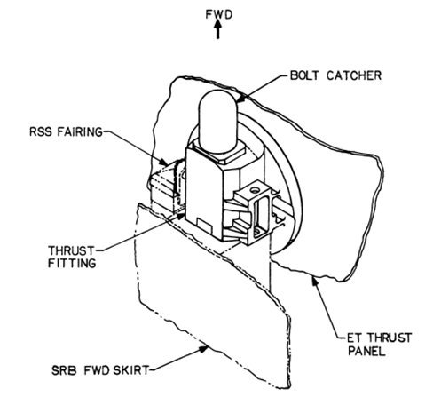  Source: System Definition Handbook SLWT, Vol. I (Lockheed Martin) Final clarity about the arrangement of the fitting on the front I then got through these two photos, here in opened state without cladding (RSS Fairing) 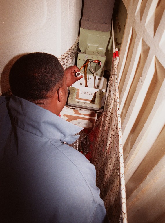 Source: NASA and here with the gray cladding, 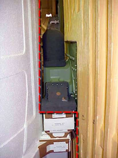 Source: spaceflight.nasa.gov which I then compared directly in this photo montage. 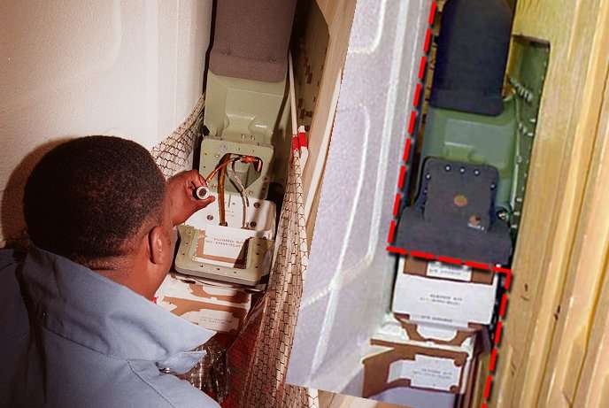 Unfortunately, I did not have these photos available during the failure of my PC, which is why I've initially only orientated myself by the first photo at the beginning of the post that I had on my smartphone, but what unfortunately has led into the wrong direction when I began scratching the arrangement, but what I still want to present to you. When scratching this fitting, I had to consider the support rod for the SRBs and drill a respective boring. For the two-part basic body of the fitting I've used a Rectangular profile (2 mm x 2,5 mm), which I rounded off at the front end to simulate the Bolt Catcher and drilled out for the holding rod with Ø 1,5 mm, as one can see in this image. 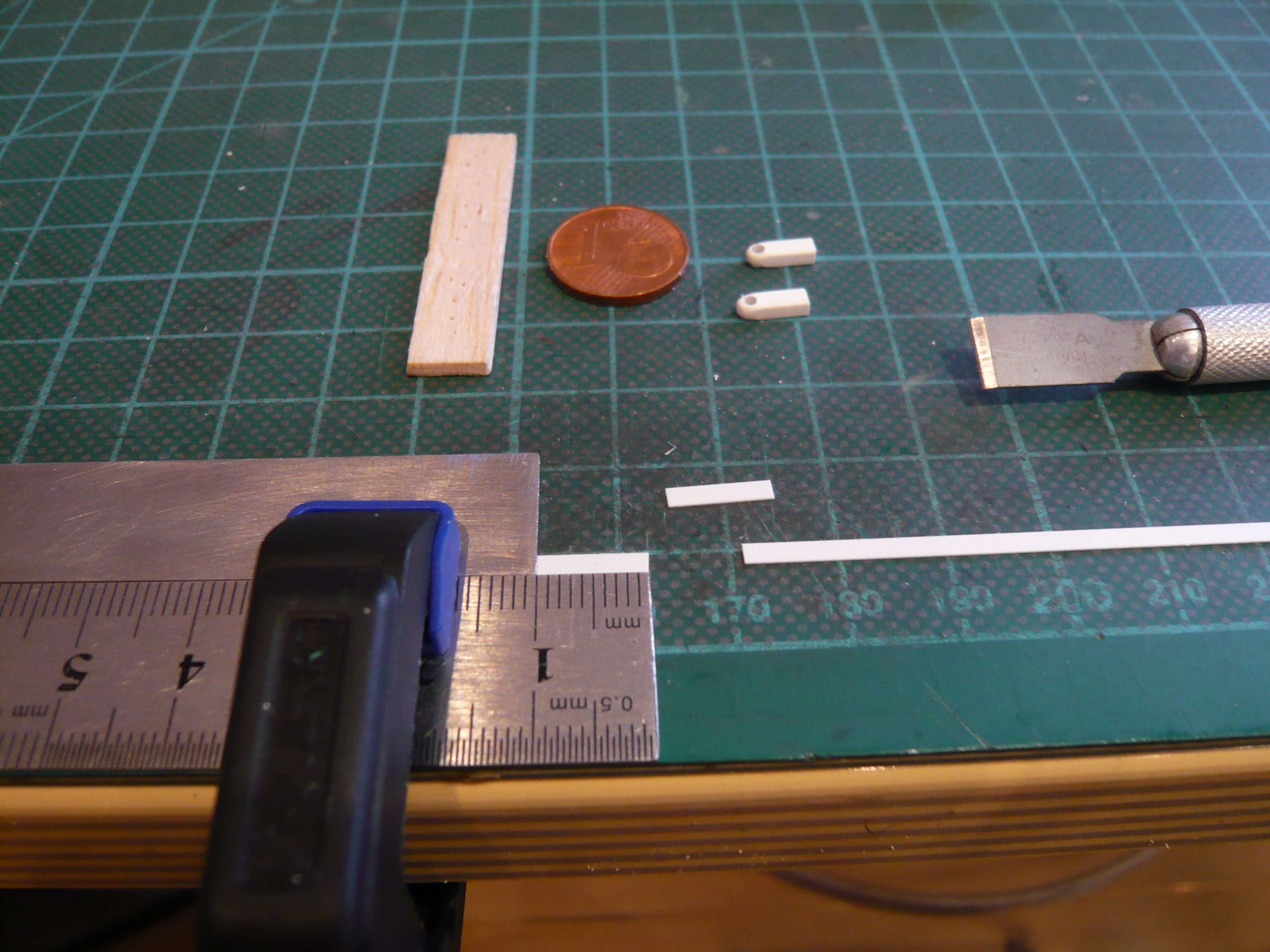 On this image one can see the assembly of a Bolt Catcher, which catches the front part of the bolt that was blasted off when the booster was separated,  Source: NASA whose honeycomb-like inner structure can be seen here in detail.  Source: NASA
__________________
Greetings from Germany Manfred Under construction: Launch Pad 39A with Challenger STS-6 (1:144)
|
|
#2088
03-29-2020, 05:25 AM
|
||||
|
||||
|
The individual parts of the ribbed back part I cut from an Evergreen Strip (0,25 mm x 2,0 mm),
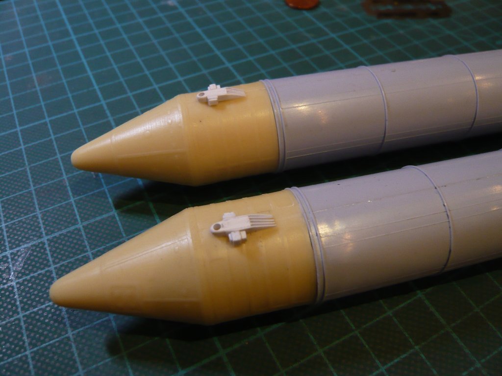
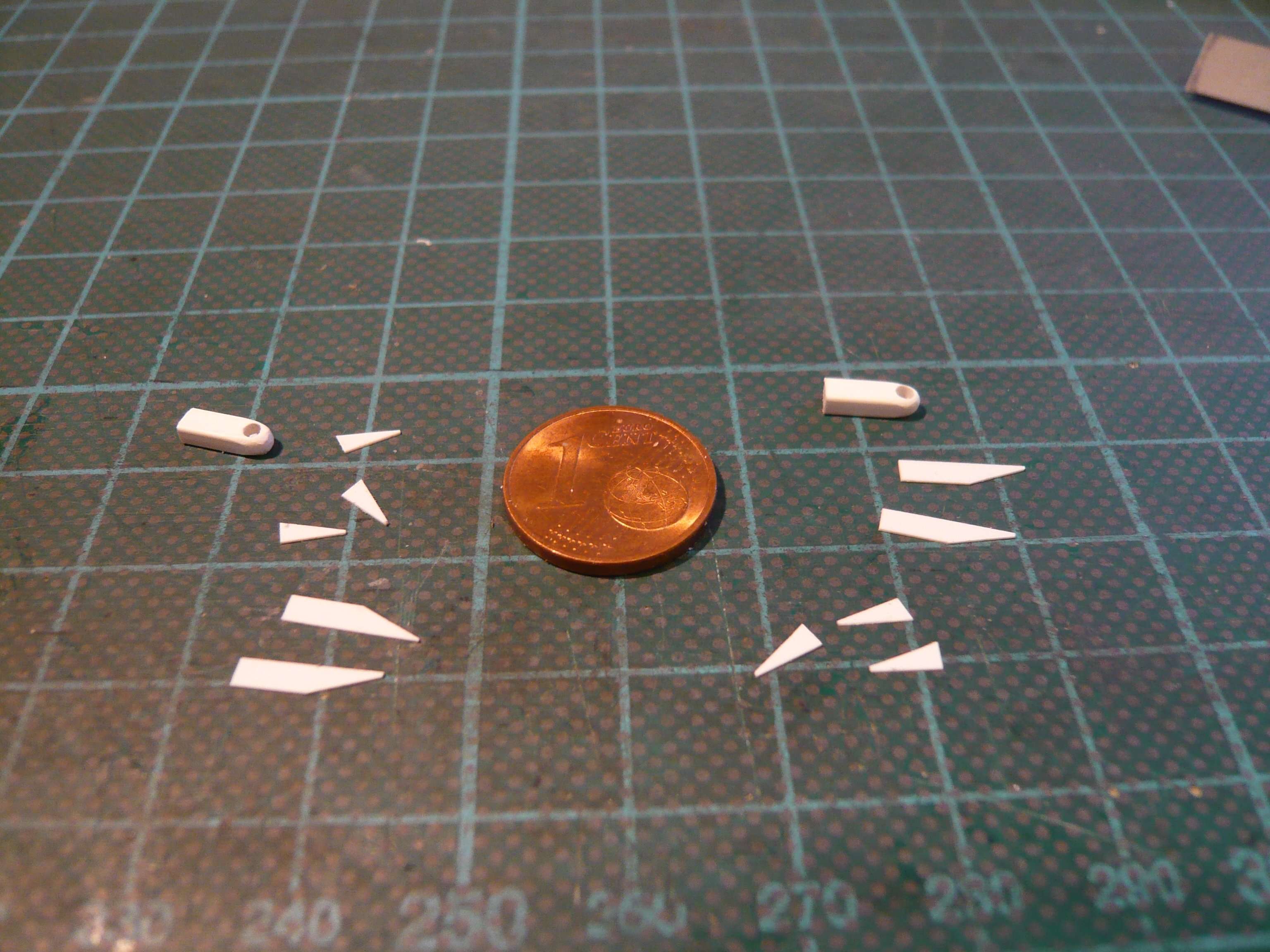 and then glued step by step with MEK onto the basic body laying on a Teflon foil. 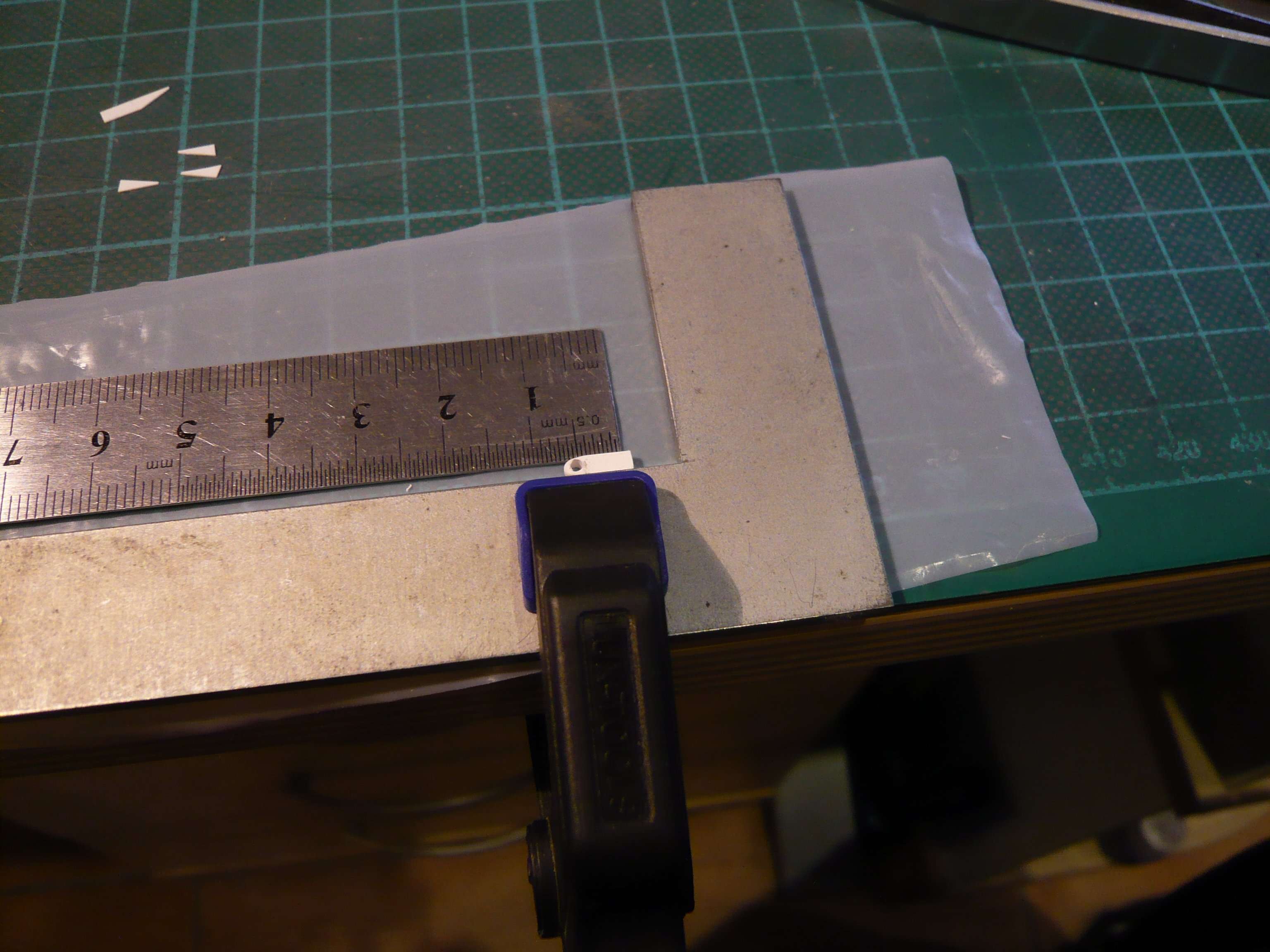 Gluing the tiny triangles was a pretty tricky task due to the minimal spacing, 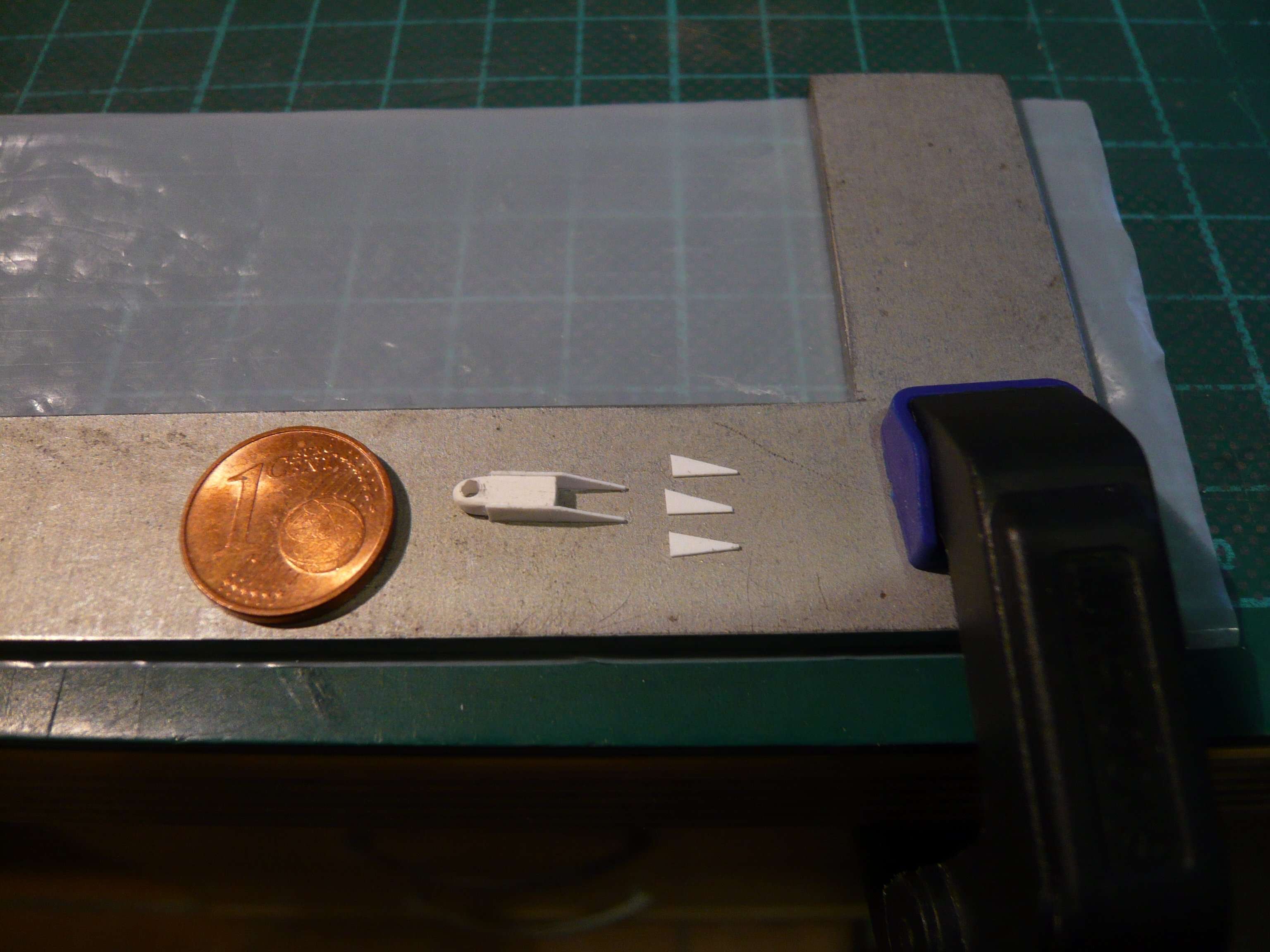 but has worked well thanks to my angelic patience and steady hand. 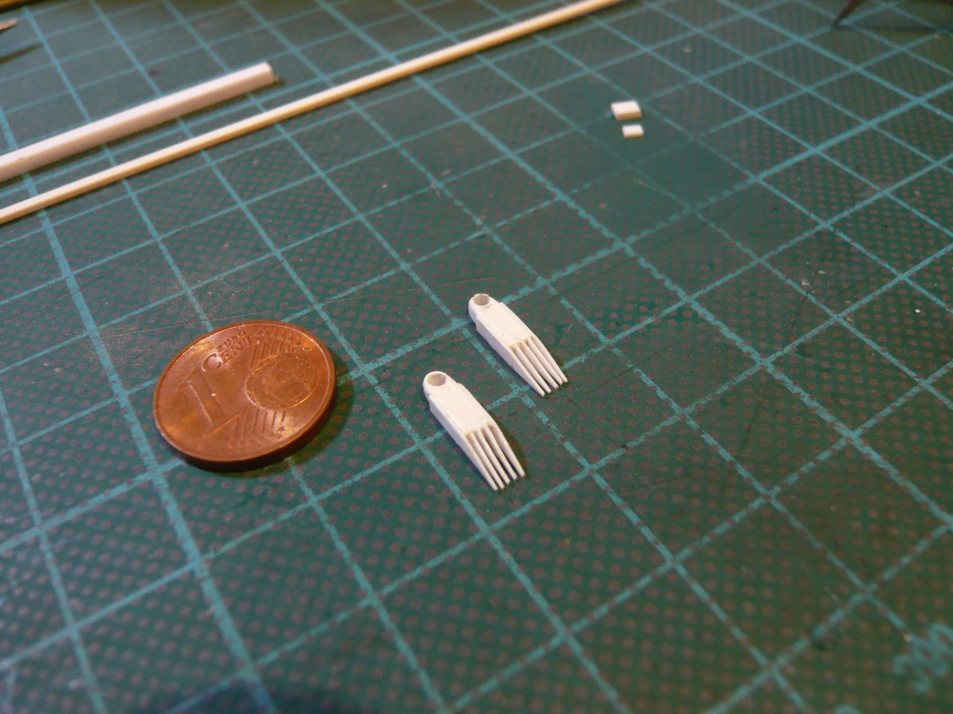 This was followed by the side attachment of the boxes on the front, which I could only reconstruct on the basis of my smartphone picture,  what then looked like that. 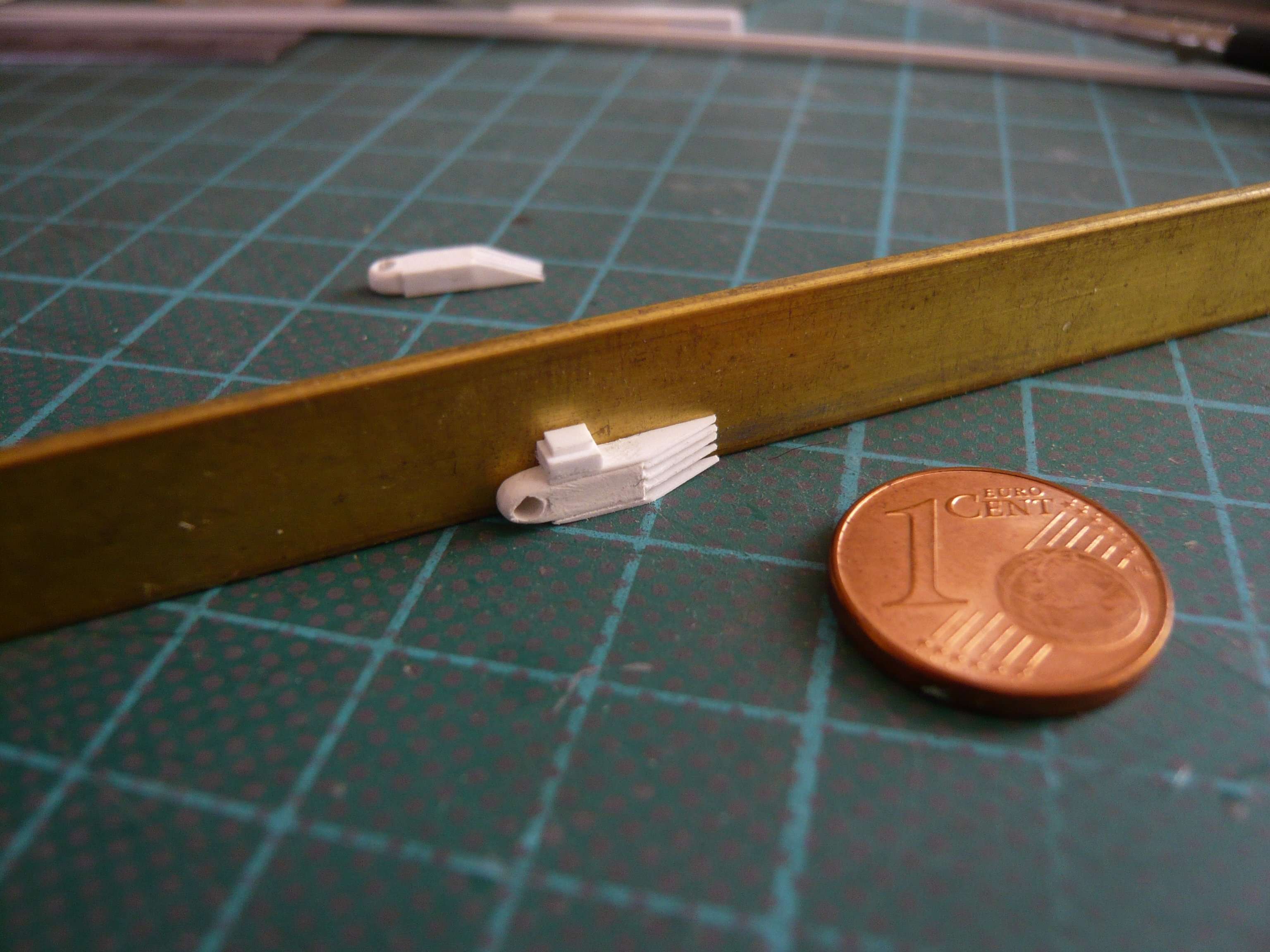 For modeling the arrangement on the back I've used this photo of the ET-45 (STS-47), although one can only guess it. 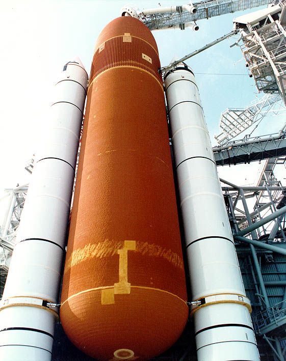 Source: georgesrockets.com (George Gassaway) But I think that it can only be a simple cover, if one looks at this zoom shot, 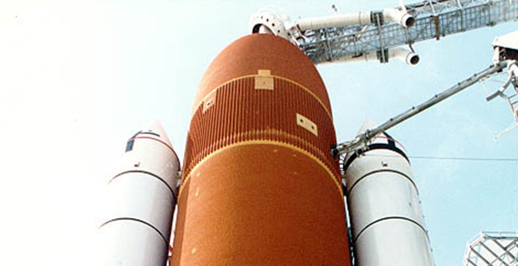 which is why I've chosen this simple form. 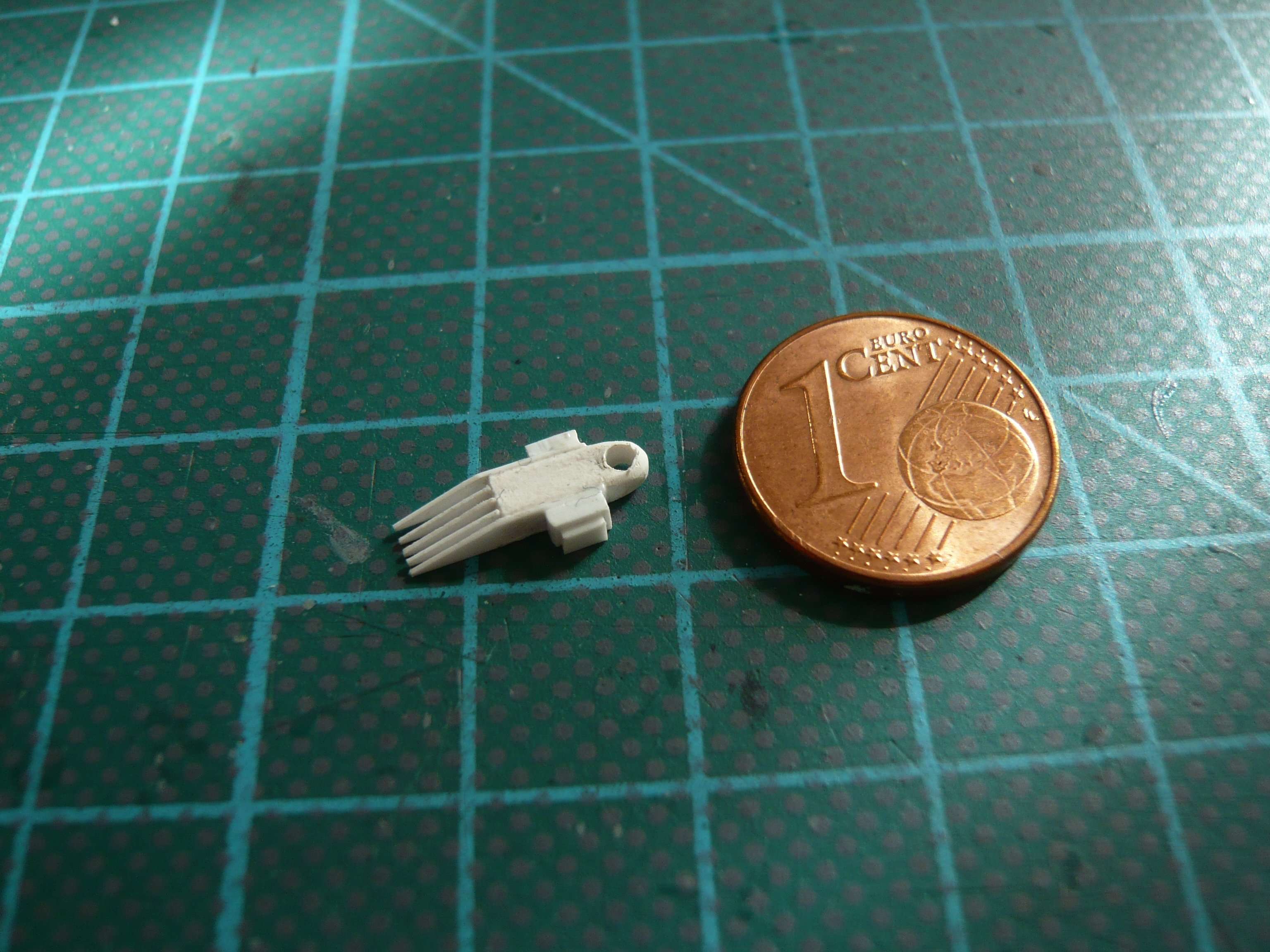 And so the finished fitting sits on the SRB, 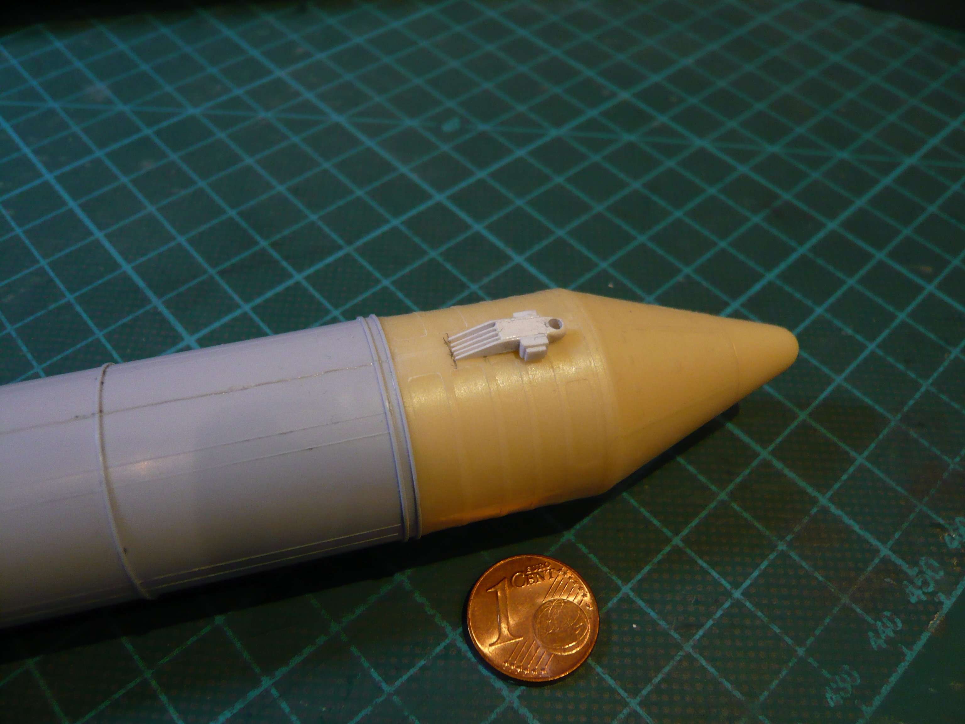 and that's how the whole thing looked with the attached SRB onto the ET, actually not bad, right? 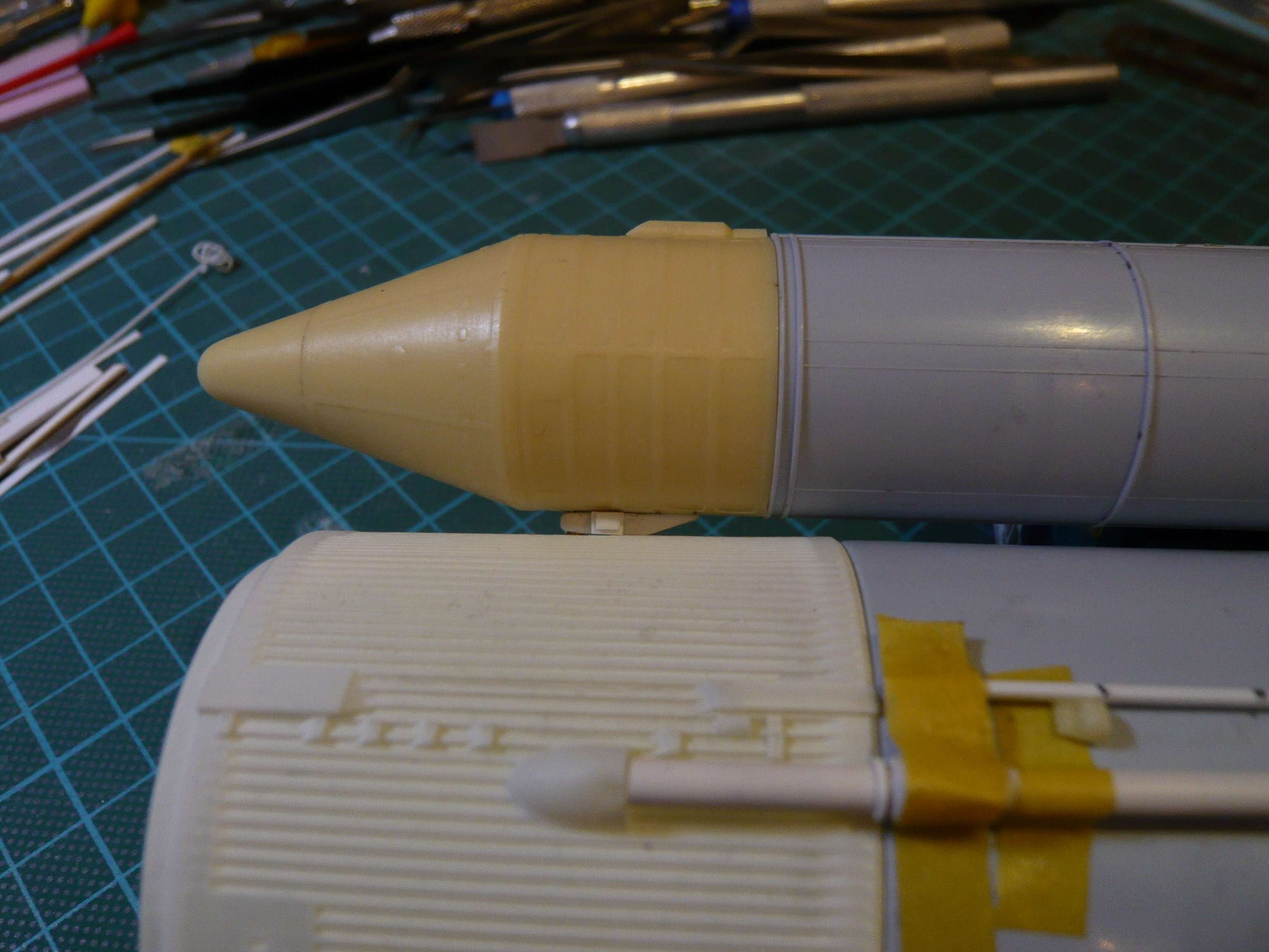 But now I'm a bit smarter  and know that the two boxes on the front are not sitting next to each other but have to sit one above the other, which is why I still have to change it once again, but be that as it may! and know that the two boxes on the front are not sitting next to each other but have to sit one above the other, which is why I still have to change it once again, but be that as it may!
__________________
Greetings from Germany Manfred Under construction: Launch Pad 39A with Challenger STS-6 (1:144)
|
|
#2089
04-04-2020, 05:47 PM
|
||||
|
||||
|
Hello everybody,
Today is an important historical date for my project, which I would like to honor with a brief review. 37 years ago today, on 4 April 1983 took off from the Launch Pad 39A the Space shuttle Challenger for her maiden flight, the STS-6 Mission, to whom I have dedicated my long-term project.  Source: NASA And now back, here comes the next update. In the meantime I have modified the ET/SRB Forward Attach Fittings a little bit, so that the two boxes with the cabling are now arranged one below the other as in the original, as was already shown here. 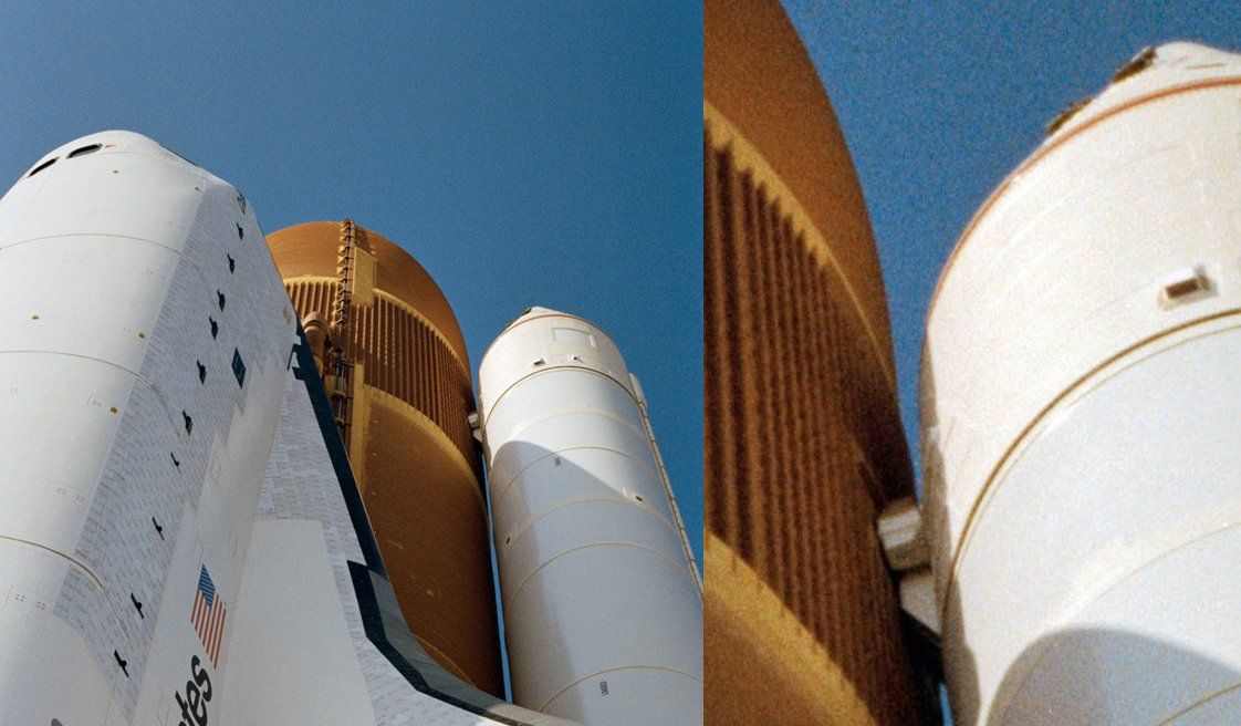 Source: forum.nasaspaceflight.com (woods170) Admittedly, this is only a small part of the entire Shuttle stack and can hardly be seen in the end, but if I am not completely convinced by the details, then I get to the bottom of the matter once more, something this time took longer because I've researched some sources more exactly again.  And this is how the new part looks with the boxes arranged one below the other, 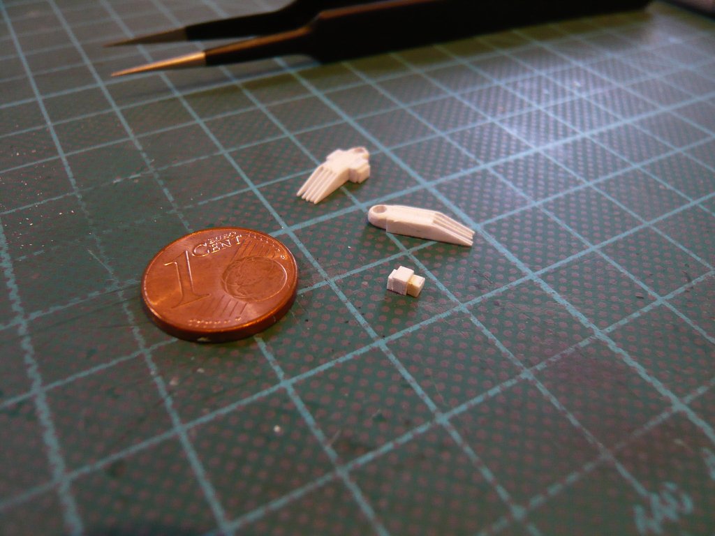 and here again in direct comparison with the previous variant (left). 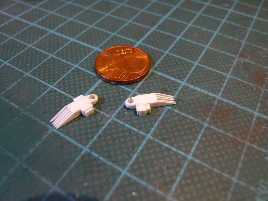 Since the new prototype initially seemed a bit too big to me, I've reduced it a bit in a second variant (below),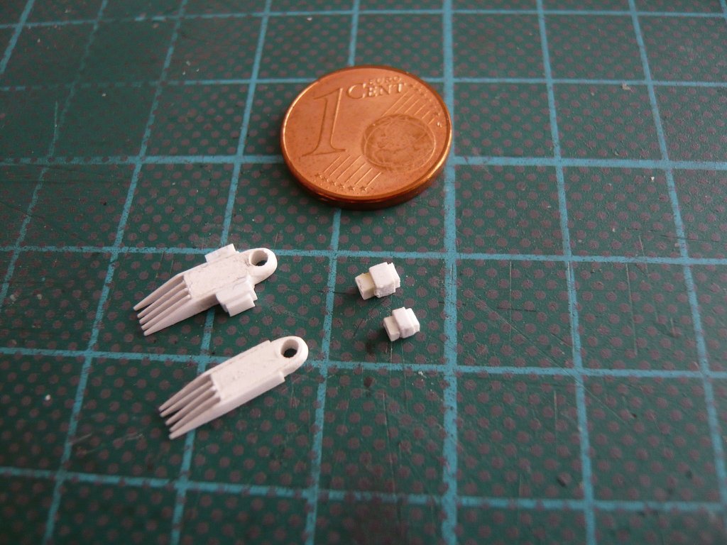 what one can see here. 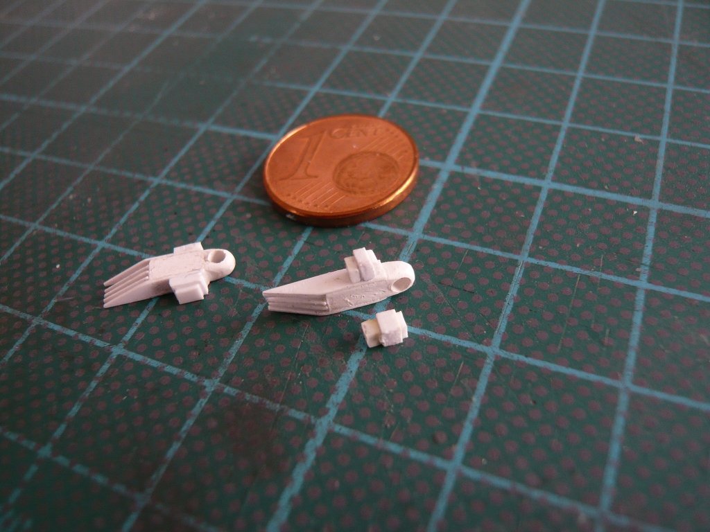 But after a detailed re-measurement based on the original photos, I still decided on the first, slightly larger version and made a copy of it for the other fitting. 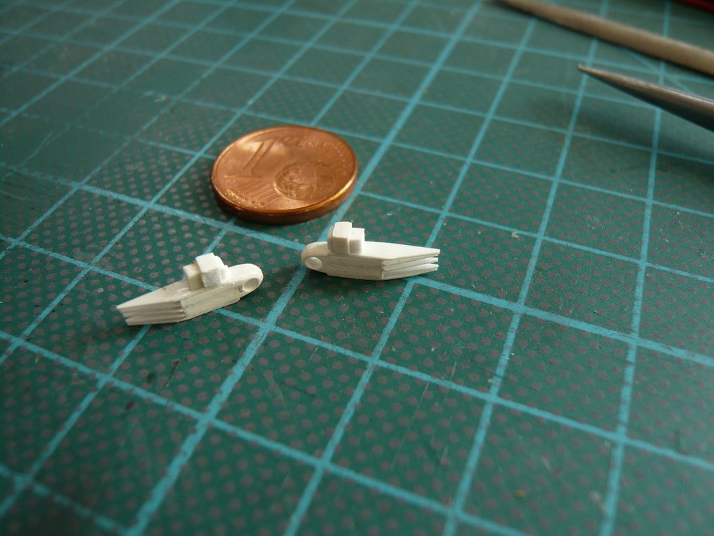 In the meantime I have also found a photo of the back of the fitting (left), which at first glance hardly differs from the front side (right) where the two boxes with the ET/SRB RSS cross-wiring were mounted. 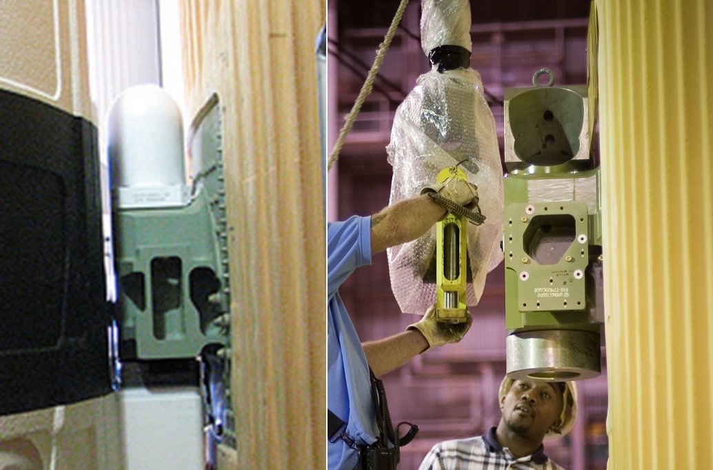 Source: forum.nasaspaceflight.com On the back there are no additional attachments like on the front, but only the receptacle for screwing the Ground Handling Fitting for the transport of the ET, 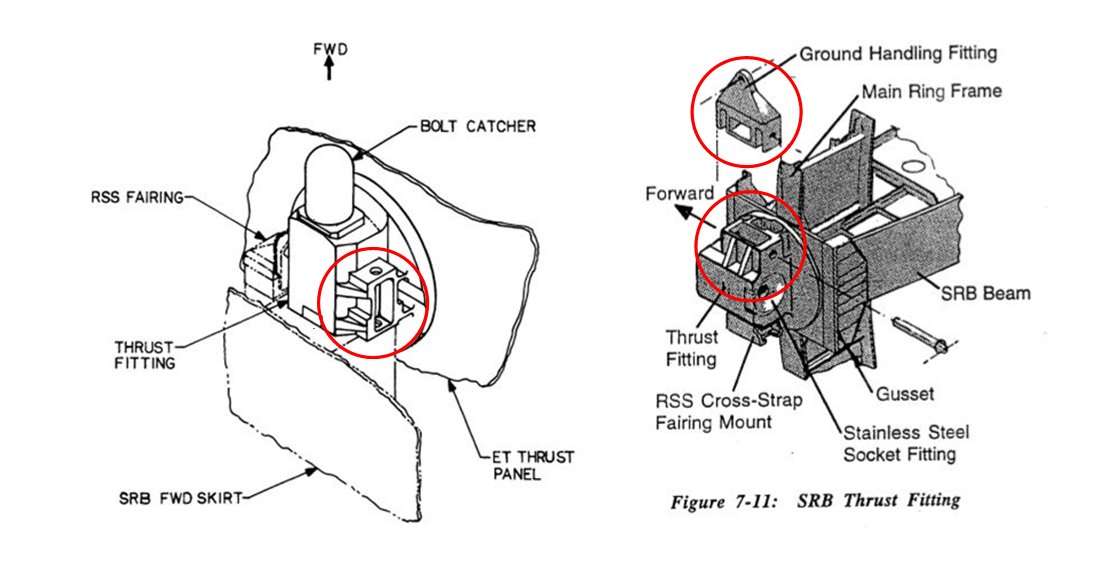 Source: System Definition Handbook SLWT, Vol. I (Lockheed Martin) which was probably covered with a cladding, which one can guess more on this picture than can see clearly, 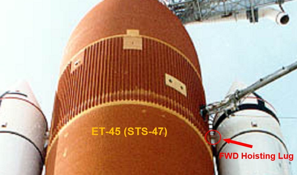 Source: georgesrockets.com (George Gassaway) what I simulated by these tiny parts. 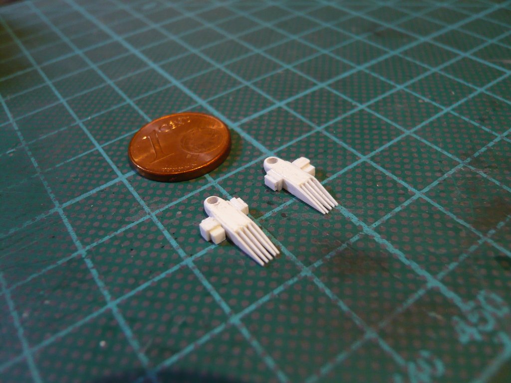 And so these attachments sit opposite each other when installed on the SRBs. 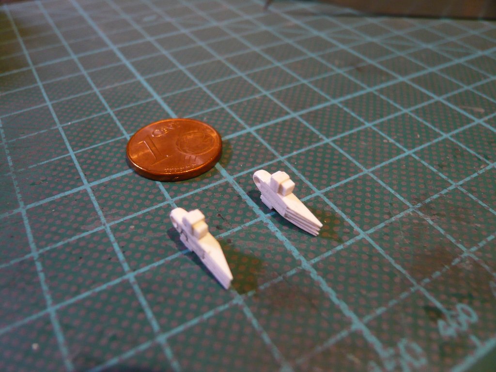
__________________
Greetings from Germany Manfred Under construction: Launch Pad 39A with Challenger STS-6 (1:144)
|
|
#2090
04-04-2020, 05:47 PM
|
||||
|
||||
 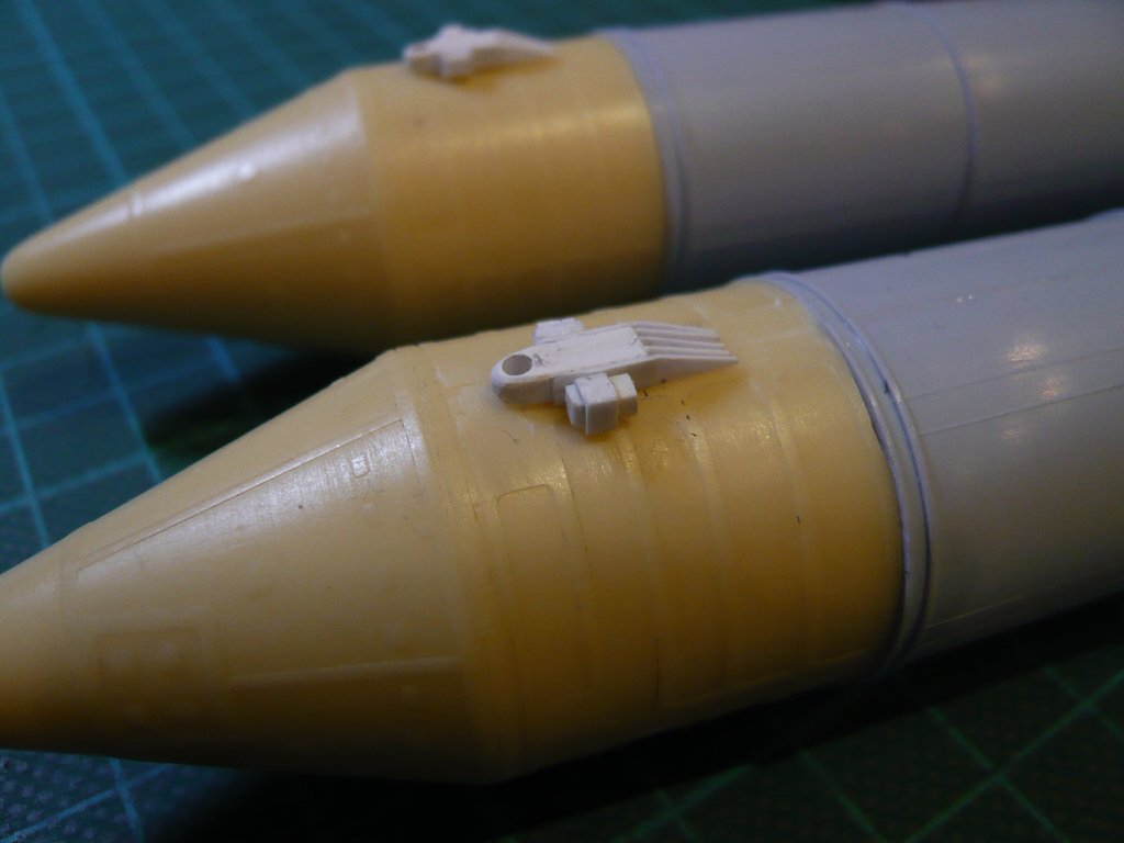 And this is how they look in the glued state, here is the view of the front of the ET, which is facing the orbiter, 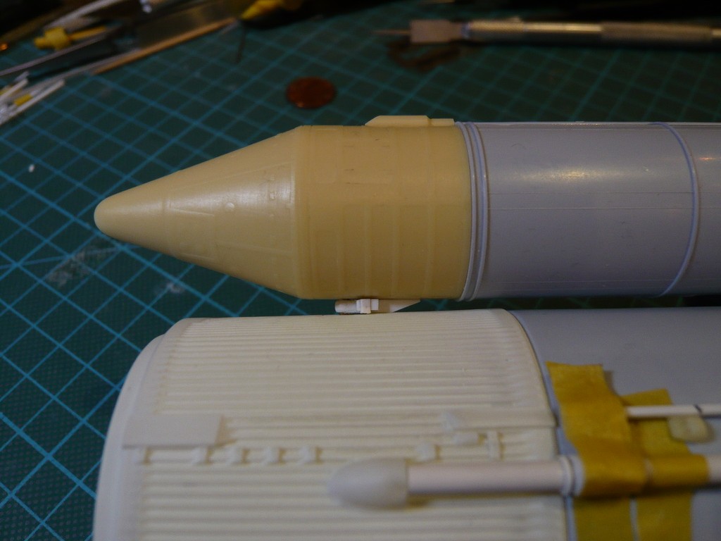 and here's a look at the back.  And with that I wish everyone a nice Sunday, and above all, stay healthy.
__________________
Greetings from Germany Manfred Under construction: Launch Pad 39A with Challenger STS-6 (1:144)
|
 |
|
|


 Linear Mode

