


|
|
|
#1371
 06-20-2017, 12:53 AM
|
||||
|
||||
|
Hello everybody,
I'm still wondering if I should try it with the 0.1 mm wires.  This would mean that I had to glue the four thin wires (0.1) parallel to each other on supports strips 1.5 mm x 0.35 mm and then to glue this fragile pipe bundle onto support feet, over the length of about 12 cm from the Bay 8 to the Bay 1 and also still around the corner to Side 1, so that the wires remain tensioned.   Source: NASA But this structure would have to be painted before, which sounds utopian,  unless one is building an intelligent retaining jig ... unless one is building an intelligent retaining jig ...  Now good advice is expensive ...  
__________________
Greetings from Germany Manfred Under construction: Launch Pad 39A with Challenger STS-6 (1:144) 
|
|
#1372
06-20-2017, 06:36 AM
|
||||
|
||||
|
Hello everybody,
this is certainly a rather demanding and complicated undertaking, which would in any case require a suitable holding jig to be able to paint this wire bundle by airbrush in a first step.  Meanwhile I have fiddled around with a solution and have also an idea already.  One would have to reproduce the girder structure of the Side 2 from Bay 8 to Bay 1, which can be seen in this image, 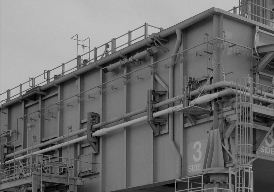 Source: Library of Congress as a kind of template made of Balsa with the tiny supports strips on girder dummies, and glue the wires on it, whereby the front ends as well as the rear ends should have to be angled already and fixed somehow.  The other pipe supports, sitting on feet on the side wall, would have to be painted and glued separately, and then one could glue the painted thin bundle with the support strips onto the girders and the other wall supports, and also lay around the corner. This sounds surely a bit adventurous and perhaps it's hard to understand too, but maybe it's possible. The difficulty results from the minimal distances of the four thin wires from only 0.2 mm on the 1.5 mm short support strips.  This filigree arrangement of the wires I have tried to apply now. First I used spring steel wire 0.1 mm, which is unsuitable because the wires are magnetically attracted by the tweezers.  But with nickel silver wire 0.1 mm it was possible and looks like this. But with nickel silver wire 0.1 mm it was possible and looks like this.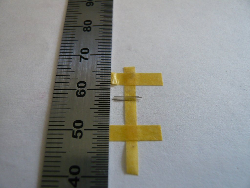 This is my momentary idea, but maybe it's also too crazy and cannot be realized, wherefore I'm still a little bit sceptical,  although my feeling tells me that it could work ... although my feeling tells me that it could work ... 
__________________
Greetings from Germany Manfred Under construction: Launch Pad 39A with Challenger STS-6 (1:144) Last edited by spacerunner; 06-20-2017 at 08:09 AM.
|
|
#1373
06-20-2017, 08:48 AM
|
|||
|
|||
|
Having a bit of trouble following the details but I get the general idea. If anyone can do this successfully Manfred, it's you, and I believe this idea will work.
__________________
This is a great hobby for the retiree - interesting, time-consuming, rewarding - and about as inexpensive a hobby as you can find. Shamelessly stolen from a post by rockpaperscissor 
|
|
#1374
06-20-2017, 03:13 PM
|
||||
|
||||
|
Thanks elliott for looking in on me,
 I can understand you, it's also a little bit tricky, to describe this crazy stuff theoretically. But the implementation in detail could become even a bit more complicated, the more I think about it, especially the airbrush painting in view of the minimal spacing of the wires of only 0,2 mm. Time will tell ...
__________________
Greetings from Germany Manfred Under construction: Launch Pad 39A with Challenger STS-6 (1:144)
|
|
#1375
06-20-2017, 06:56 PM
|
||||
|
||||
|
I would think the deciding factor would be whether you can get the wires to come out straight and parallel over that distance.
|
|
#1376
06-21-2017, 10:29 AM
|
||||
|
||||
|
Hi Becky,
I fully agree with you, this might be the crunchpoint, I think too. And therefore it might be better to lay the wires individually with a distance stencil.
__________________
Greetings from Germany Manfred Under construction: Launch Pad 39A with Challenger STS-6 (1:144)
|
|
#1377
06-22-2017, 06:03 AM
|
||||
|
||||
|
Hello everybody,
while the holding device assumes more and more shape in my mind's eye, I also have to understand the course of the Fuel Cell Pipes, especially their starting points on the Side 2 in the Bay 7 (GH2) and Bay 8 (GO2), as well as their further course to the MLP corner and then on the Side 1.  For this purpose here are a few pictures for illustrating the wiring course, for the sake of simplicity, just behind the corner on the Side 1, whereby the two upper lines are the GO2 Pipes, and the two lower ones the GH2 Pipes. 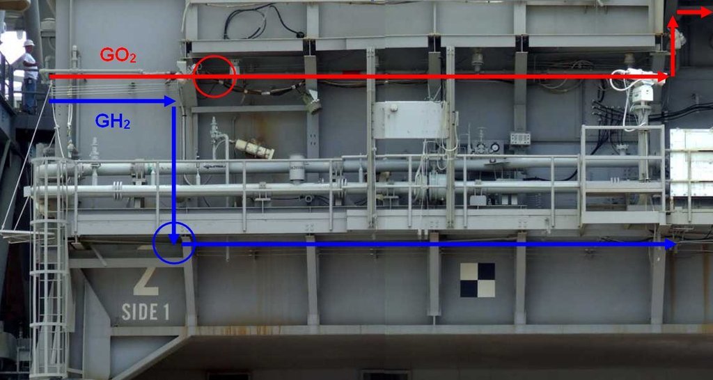 Source: NASA While the two GO2 Pipes are running below the Blast Shields to the LOX Tunnel, the two GH2 Pipes run downward in front of the Blast Shield and then below the AccessPlatform up to the LOX Pneumatic Interface Plate in the Bay 6. And so it should fully suffice if I let end up the pipes at the circled places, especially since one can not see their further course on the model.  But regarding the starting points of the Pipes on Side 2 in Bay 7 and Bay 8, it's still not quite clear in detail, because one can not recognize it exactly enough, which is why I initially thought that the pipes would come out of the MLP wall. 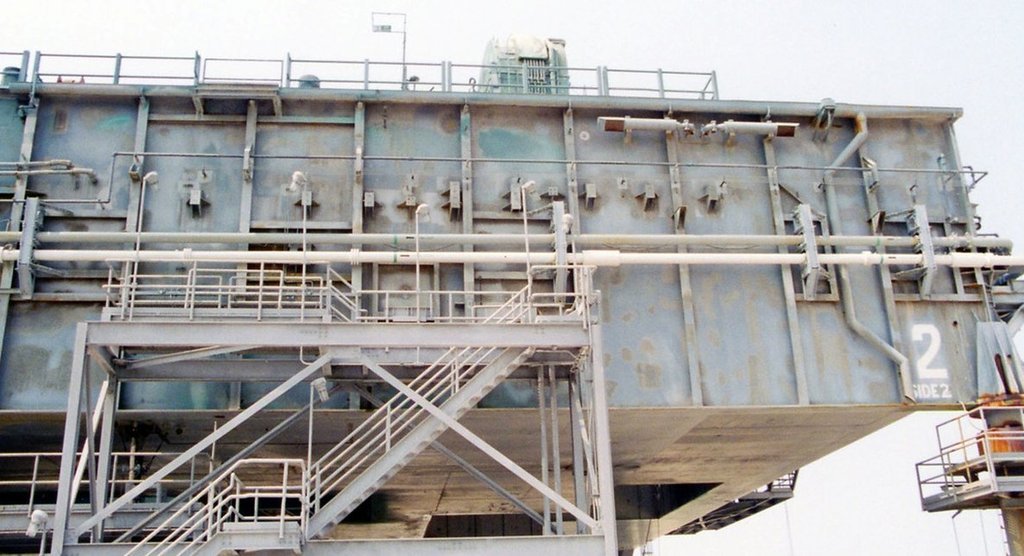 Source: apollosaturn.com (John Duncan) And even this image, which reveals more details already, cannot give a more exact explanation. 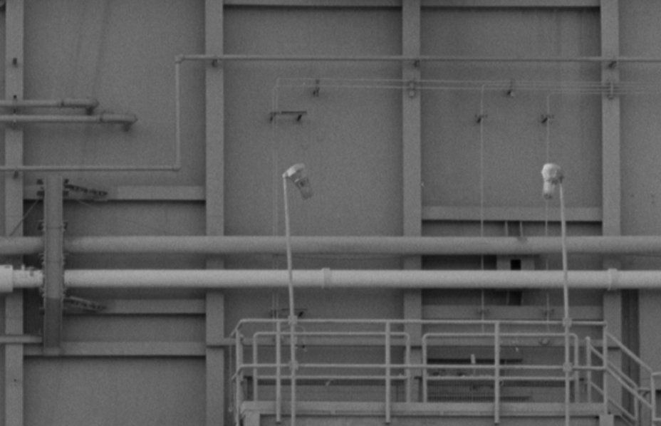 Source: Library of Congress It is only clear that the two GH2 Pipes in the Bay 7 running down close to each other, while the two GO2 pipes in the Bay 8 run with a significantly larger distance.  But then suddenly I remembered, that there is a NASA panorama with a great view of the Side 2 of the MLP-2 from Level 75 on the FSS, on which these two bays might be visible more detailed.And lo and behold, quite right, and therefore here the ultimate shot with the linked panorama, 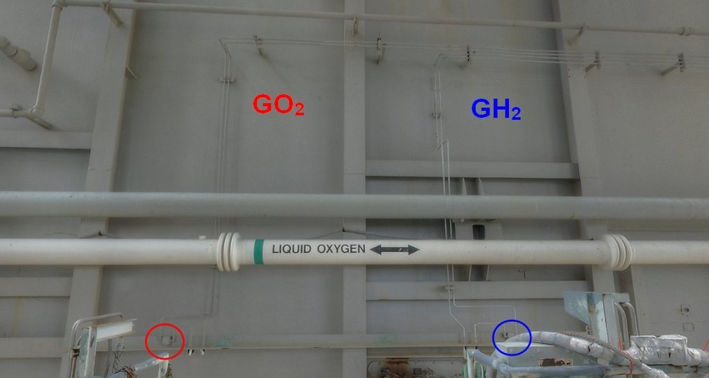 Source: NASA wherewith (now) almost all the uncertainties for scratching should be eliminated.  As can be seen, the pipes start on an angle profile and then take a multiple angled course upwards, and follow after merging in the Bay 7 as a quadruple bundle to the right up to the beginning of the side. As coming from NASA's plans, the circled jacks are Moisture Sensors, and one can even see how the pipes are bolted to the angle profile. 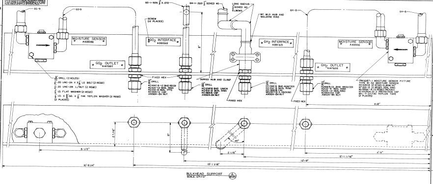 Source: NASA And with that the matter looks already much more friendly.
__________________
Greetings from Germany Manfred Under construction: Launch Pad 39A with Challenger STS-6 (1:144)
|
|
#1378
06-28-2017, 09:33 AM
|
||||
|
||||
|
Hello everybody,
the Fuel Cell Pipes are put aside and let's look again to the Bay 18, 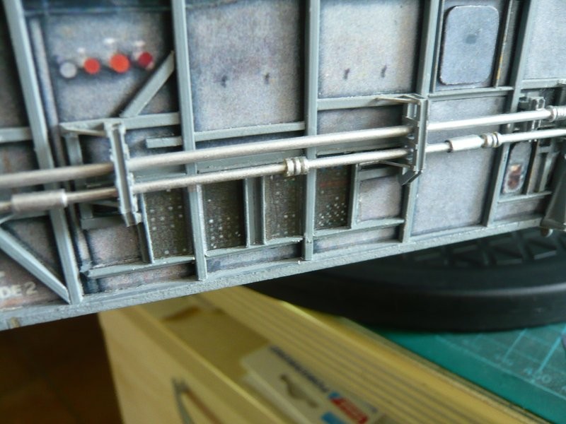 in which are still to install the through-sleeves and connection sockets of the three ports for the ECS purge lines. Here is again the original using the example of the MLP-1. 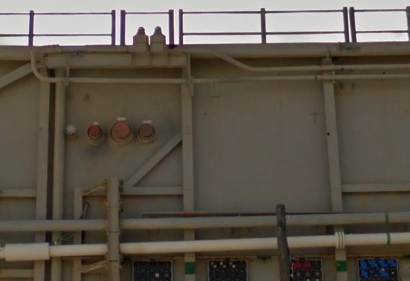 Source: NASA (Street View) These are the painted and shortened parts, 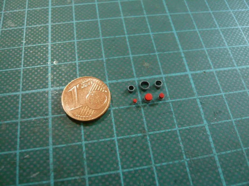  and here on the tailor-made insert. 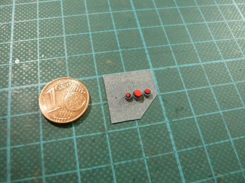 And here ist still the GN2 line with the blind flange. The eight screws I tried to hint with a fineliner, but what not still convinced me. 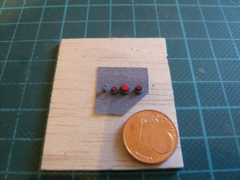 But the next attempt was already better. 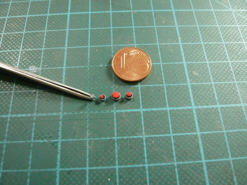  Since the through-sleeve (Ø 1 mm) was somewhat too long, it was inserted into the wall, 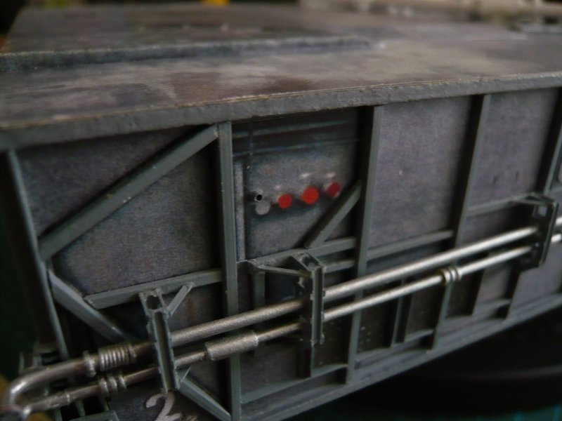 and then the insert was finally glued over it. 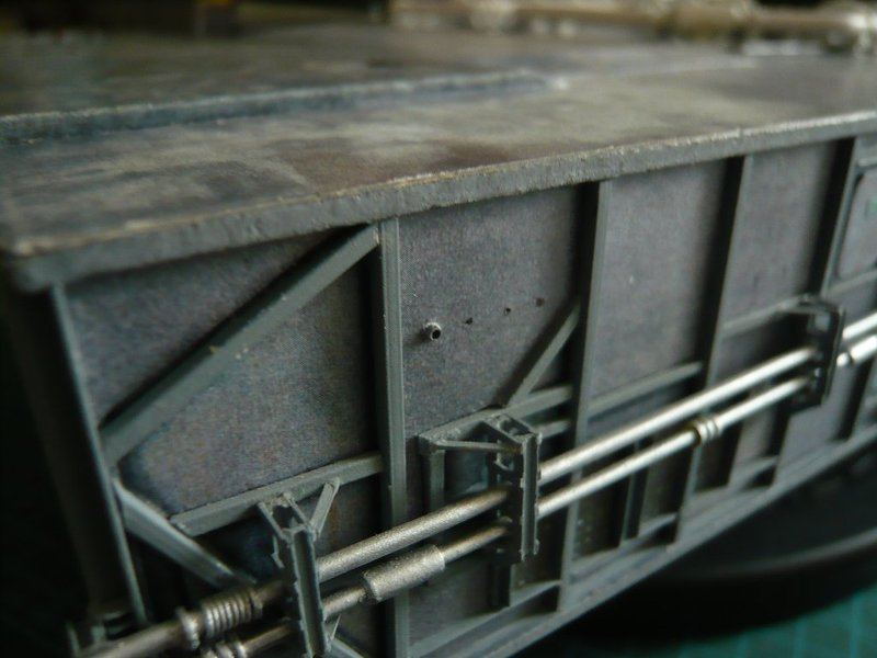 The GN2 line was initially inserted only temporarily, since its installation height must match the height of the connection sockets, 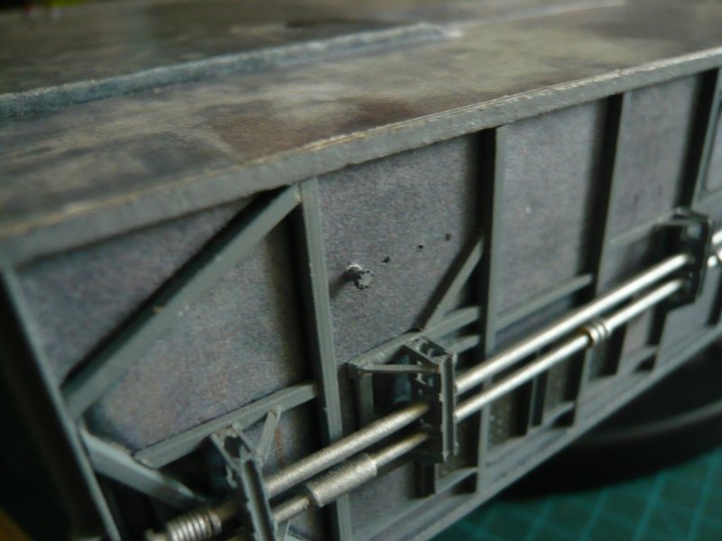 which were subsequently glued. 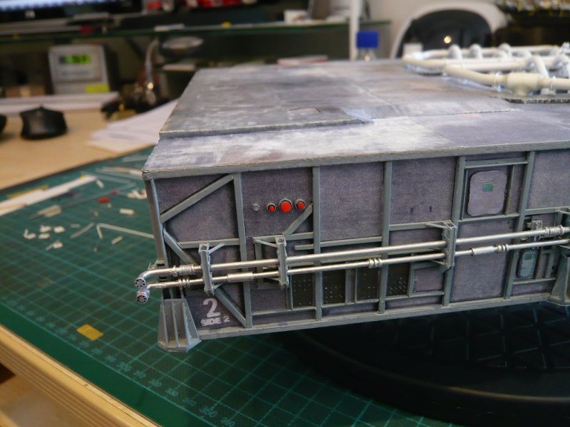 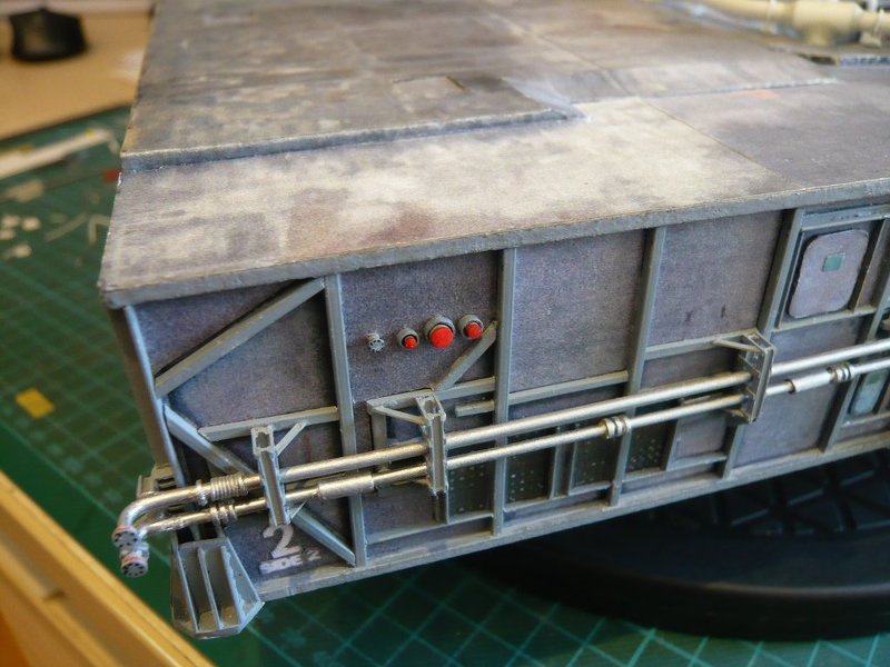 And with this result, I am now quite satisfied, although the too bright red could be mitigated by a final Washing.  But a small thing is still missing, if one looks closely, namely? But a small thing is still missing, if one looks closely, namely? Exactly, the labelings above the three ports are still missing and have been added by carefully removing the color with the cutter. 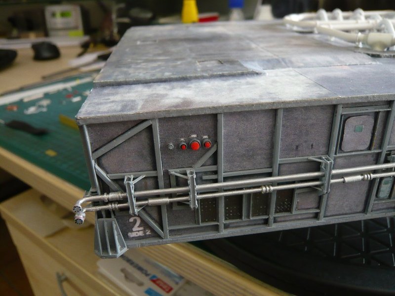 Fortunately one must not be able to decipher them. And here once again for comparison, how the ports looked before in 2D ...
__________________
Greetings from Germany Manfred Under construction: Launch Pad 39A with Challenger STS-6 (1:144)
|
|
#1379
06-28-2017, 01:00 PM
|
|||
|
|||
|
I don't know how you do such microfine work Manfred. It looks perfect though. Are you a surgeon or do you do such tiny work in real life?
__________________
This is a great hobby for the retiree - interesting, time-consuming, rewarding - and about as inexpensive a hobby as you can find. Shamelessly stolen from a post by rockpaperscissor
|
|
#1380
06-28-2017, 04:27 PM
|
||||
|
||||
|
Thanks elliott for your nice compliments.
I am not a surgeon, and also not a sorcerer.  But I had already always a preference for small and tricky details that I try to scratch, so as to give the model even more life and originality. And through a lot of practice my skill became always successlful better over the course of time. But I had already always a preference for small and tricky details that I try to scratch, so as to give the model even more life and originality. And through a lot of practice my skill became always successlful better over the course of time. Now I am retired, earlier I used to work in materials research, and this scientific curiosity is still inside me, which is why I try to get to the bottom of things.
__________________
Greetings from Germany Manfred Under construction: Launch Pad 39A with Challenger STS-6 (1:144)
|
 |
|
|


 Linear Mode

