


|
|
|
#1251
 01-17-2017, 08:16 PM
|
||||
|
||||
|
Every time I check in on your progress I'm amazed!
 I just don't want to keep saying as I don't want to sound like a broken record! I just don't want to keep saying as I don't want to sound like a broken record!  Can't wait to see this finished but I'm enjoying watching you so much I don't want it to end either! Can't wait to see this finished but I'm enjoying watching you so much I don't want it to end either! Becky 
|
|
#1252
01-18-2017, 06:12 AM
|
||||
|
||||
|
Thanks Becky for your nice compliment.
 It is already strange, but also in our German Raumcon Forum, a friend already expressed the same wish that this project should never end ...  But I can comfort you at least a little bit, because until I will come to the LC-39 diorama, a few years will still pass ... Let's see who's still watching until then ...  BTW, as I have seen, you are building your grandiose project Impressions of Disneyland already since similarly long time, which highly impressed me by your great ideas and your amazing skill.  Keep it up!!!  
__________________
Greetings from Germany Manfred Under construction: Launch Pad 39A with Challenger STS-6 (1:144)
|
|
#1253
01-18-2017, 06:21 AM
|
||||
|
||||
|
Hi all together,
and thus in the fast passage to the second clamping ring lattice with the known procedures:  Fixing the longitudinal and transverse strips, 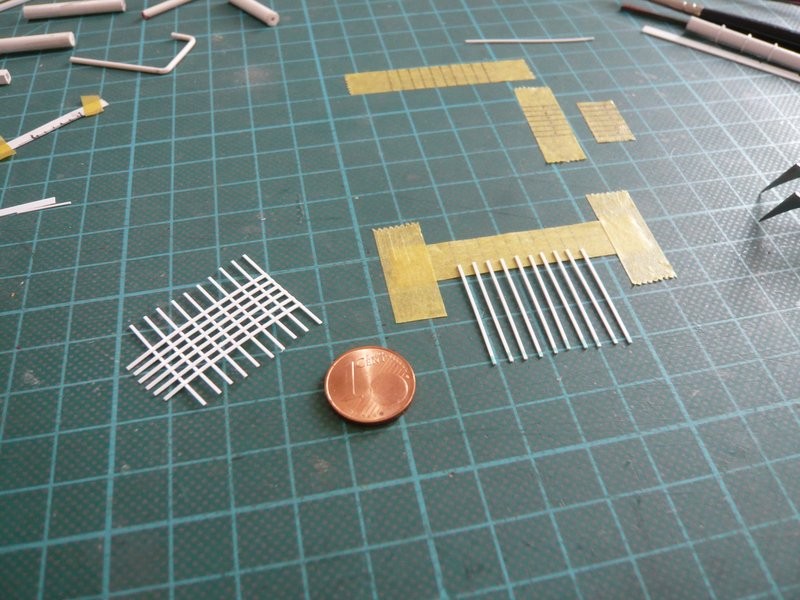 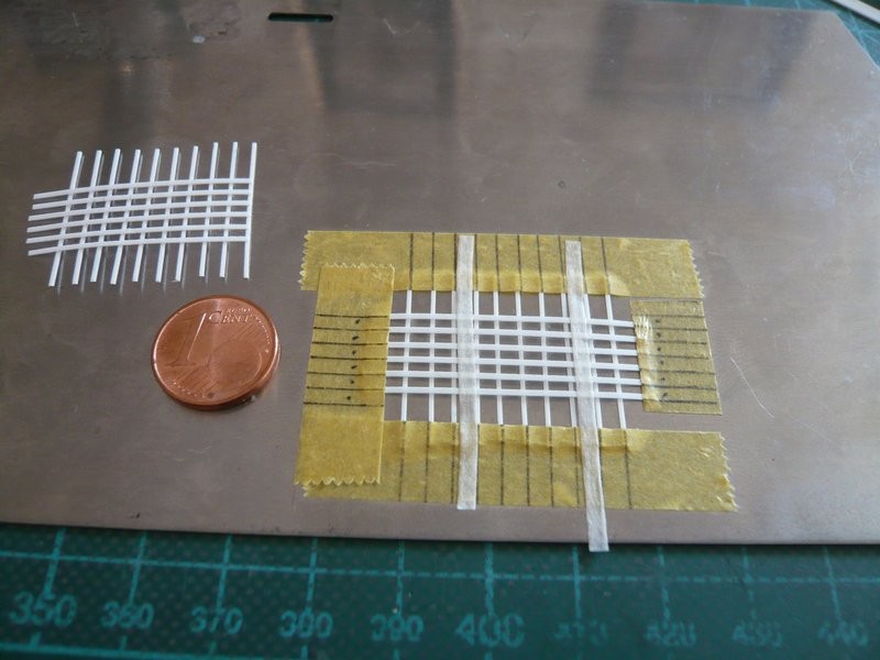 as well as gluing the cross points with MEK. 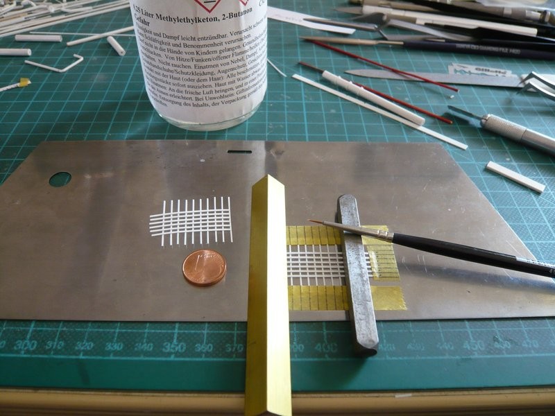 The lattice, which has been smoothly adhering to the sheet metal, can easily be detached with a razor blade.  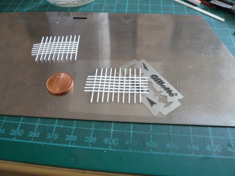 After that the stressful rounding off of the filigree edges had to be done again, which this time because of the closer distances of the screwing strips was somewhat more difficult.  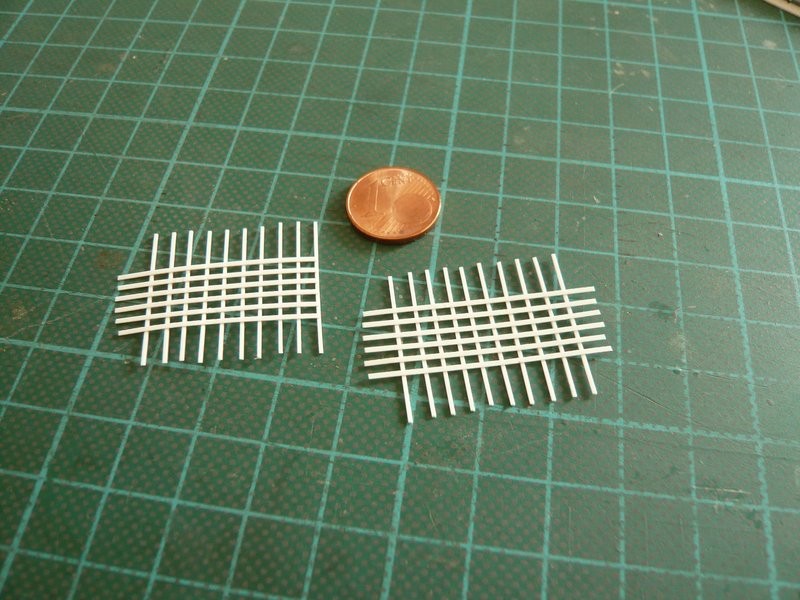 That's why I've come up with a narrow mini-file for the narrow spaces, for which I have glued a 1 mm wide strip of fine sandpaper (500) to a 2.5 mm Evergreen channel.   And these first ten of the required 19 six-part clamping rings are the result of this laborious fiddling.   And next time follows the same procedure again at the 2nd lattice.
__________________
Greetings from Germany Manfred Under construction: Launch Pad 39A with Challenger STS-6 (1:144)
|
|
#1254
01-18-2017, 11:15 AM
|
|||
|
|||
|
I may not post all the time Manfred but am thoroughly enjoying watching your steady progress through thorny problems and brilliant solutions.
__________________
This is a great hobby for the retiree - interesting, time-consuming, rewarding - and about as inexpensive a hobby as you can find. Shamelessly stolen from a post by rockpaperscissor 
|
|
#1255
01-18-2017, 11:30 AM
|
||||
|
||||
|
Thanks elliott for your kind remarks,
I can understand you well, what should one write again and again without repeating ... Nevertheless I am glad about every comment, thanks for watching.
__________________
Greetings from Germany Manfred Under construction: Launch Pad 39A with Challenger STS-6 (1:144)
|
|
#1256
01-18-2017, 03:35 PM
|
||||
|
||||
|
Hello everybody,
today I have disassembled the 2nd grid and rounded the edges on the remaining 10 clamping rings and their screw connections on all sides. And I can tell you, with the last stripes my eyes began to tear more and more,  because in the long run this is too strenuous, because the edges are so tiny. because in the long run this is too strenuous, because the edges are so tiny.  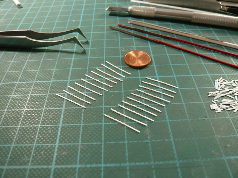 That's why I've counted once for fun the edges, which I have rounded off with my mini-files at the total of 28 clamping rings.  And what would you estimate if I would ask you? Well, since I myself was surprised, I'm going to say it immediately: believe it or not, a total of 900, hardly to believe but true !!!  And now it's time to get the SSWS skeletons out of the SRB Holes in order to glue all the clamping rings.   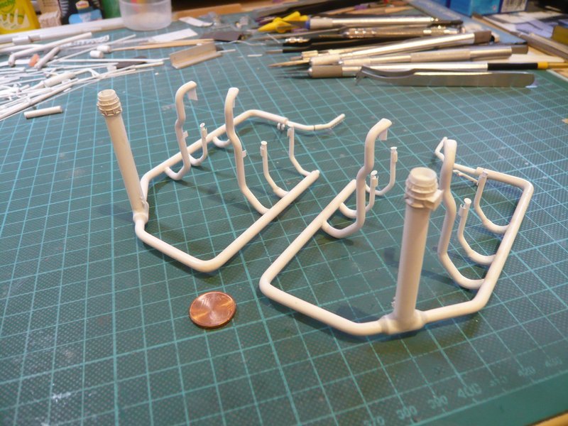 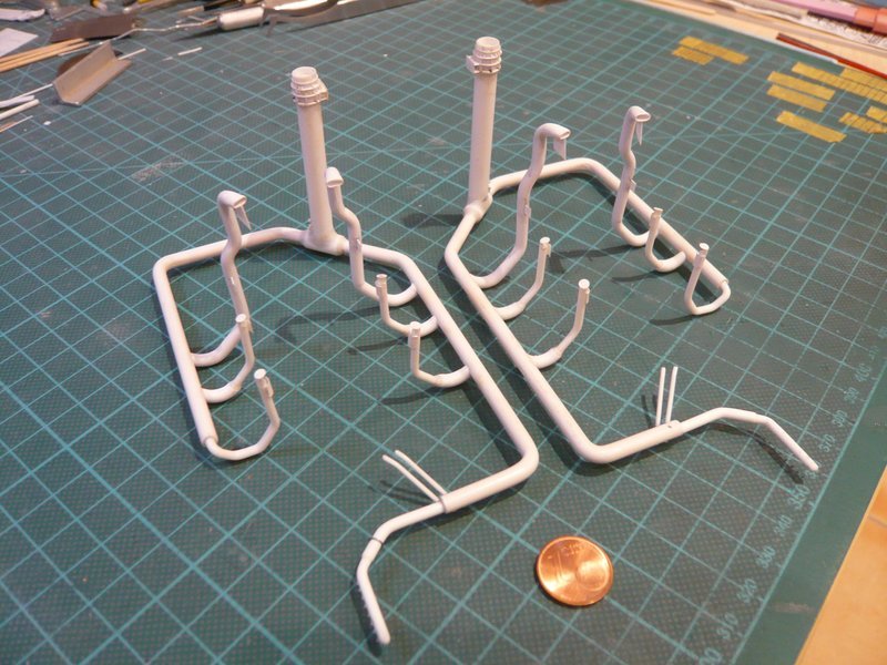 But first I have to deal with the transitions at the outlets and to model them with Apoxie Sculpt.
__________________
Greetings from Germany Manfred Under construction: Launch Pad 39A with Challenger STS-6 (1:144) Last edited by spacerunner; 01-19-2017 at 11:03 AM.
|
|
#1257
01-25-2017, 05:59 AM
|
||||
|
||||
|
Hello together,
but before I start with the Apoxie Sculpt modeling, there's still something else to do. After removal the ring lines, I have noticed that in front of the 16''/12'' transition behind the LOX-TSM the clamping ring still lacked, as one can see in the right circle. 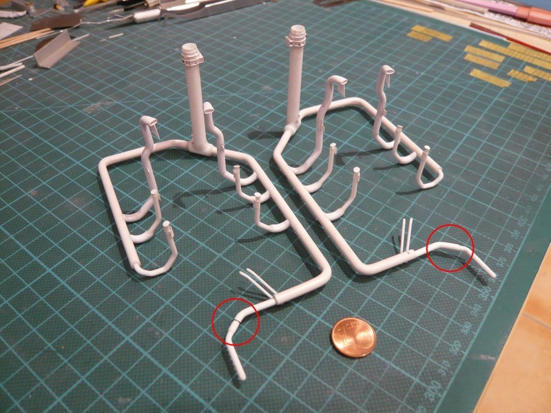 The rings for this I had (only) bent from lead wire (Ø 0,4 mm) at that time. 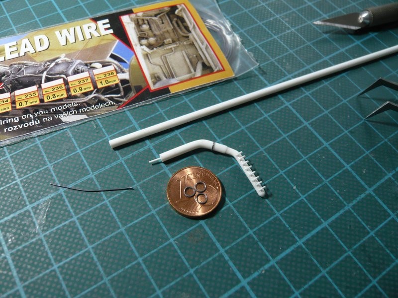 But in reality, these are two-part clamping rings with laterally fitting screw connections,  Source: NASA 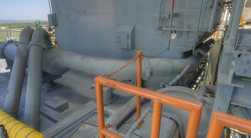 Source: NASA which could also be made by the successful lattice technique. And just during this consideration, a friend from the Raumcon Forum has sent me a piece of Teflon foil (PTFE, 0.05 mm), which I should try as underlay during the MEK-gluing.  Onto this idea one must only come up, especially since PTFE is known for its excellent anti-stick properties. For as you may remember perhaps, the strips lattice glued with MEK adhered on the metal sheet, which surprised me.  And I have now tried the same with the both two-part clamping rings, meaning no metal sheet than underlay, but only the Teflon foil on the cutting mat on which the clamping ring strips were fixed. Subsequently, the crossings were dabbed with MEK as before and so glued. 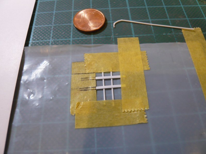 And lo and behold, nothing remains adhered, and the bondings can be removed from the foil easily and without any problem.  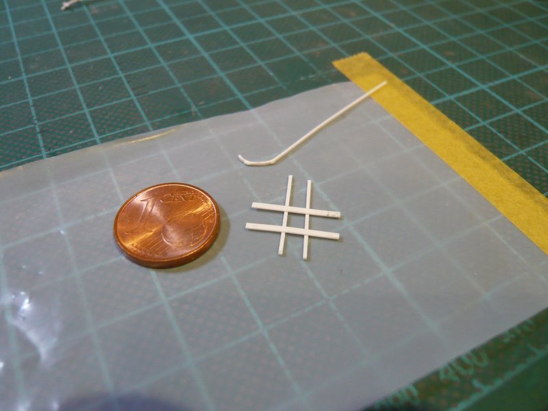 And these are the two clamping ring strips with the two screw connections. 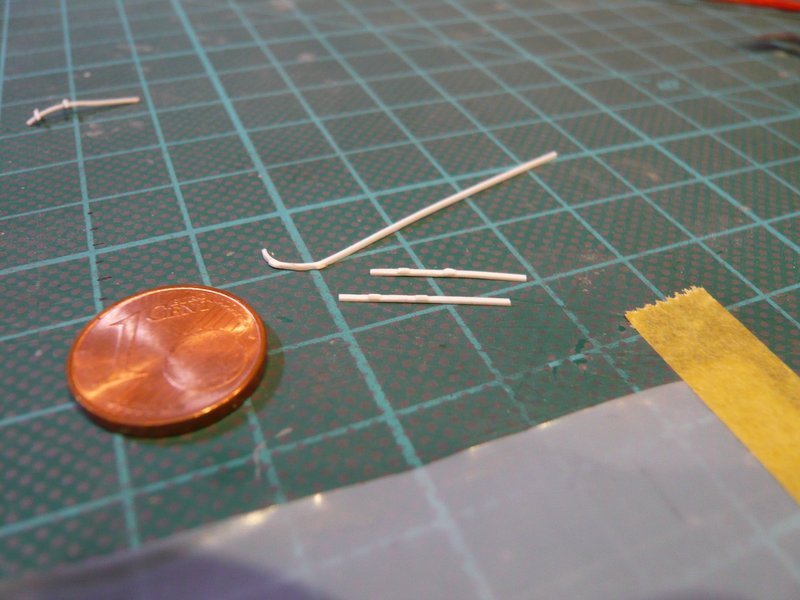 As far as for today.
__________________
Greetings from Germany Manfred Under construction: Launch Pad 39A with Challenger STS-6 (1:144)
|
|
#1258
01-31-2017, 06:13 PM
|
||||
|
||||
|
Hello everybody,
unfortunately I've got a lumbago, what is not so funny, but when sitting comfortably, it is still tolerable, so I once tried one of these both two-part clamping rings. Because of the smaller pipe diameter (2.5 mm) this time I used an Evergreen strip 0.25 mm x 0.5 mm for the ring, and for the screw connections 0.25 mm x 1 mm.I hope one can still recognize the clamping ring behind the bow, 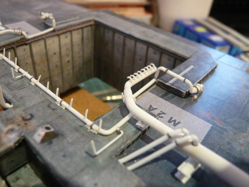 this one here is it,  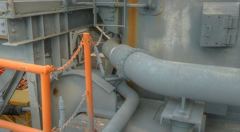 Source: NASA and therefore here once somewhat larger.  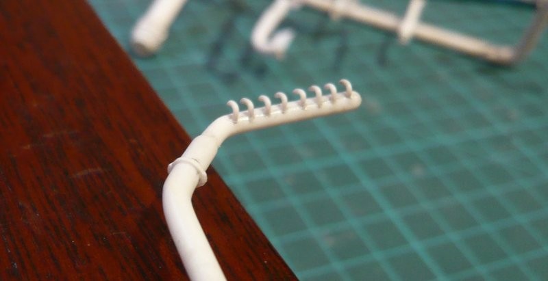 Subsequently, I have started modeling the transitions at the rejuvenations of the ring lines and first rolled Apoxie Sculpt balls and then mixed them. Here is the preliminary result, first at the 24''/12'' transition, which is still accessible relatively easy, 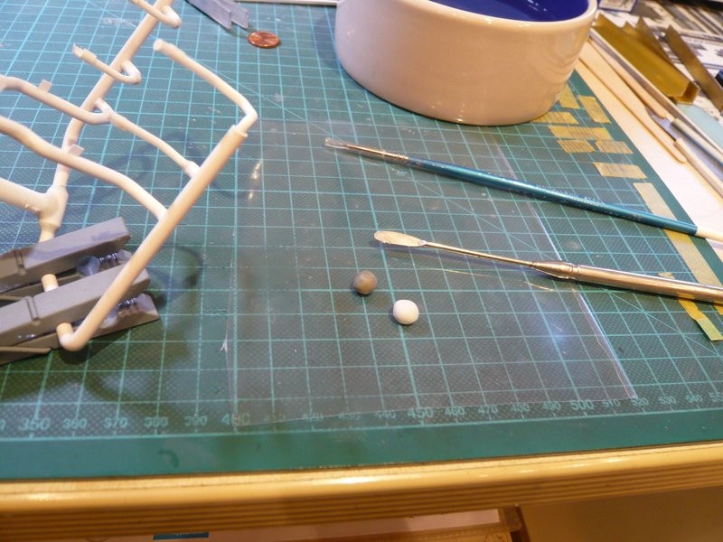 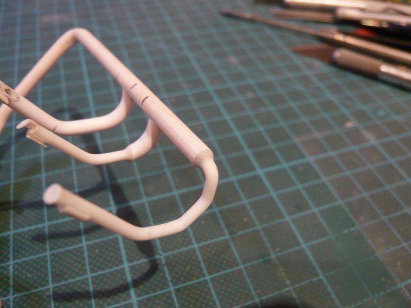 and then here at the 24''/16'' transition, which was somewhat trickier because the two 6'' outlets are unfortunately in the way.  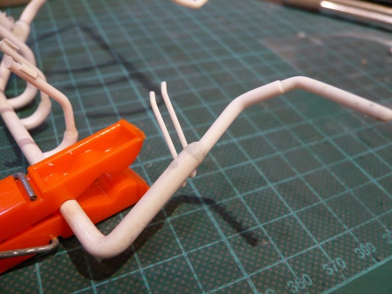 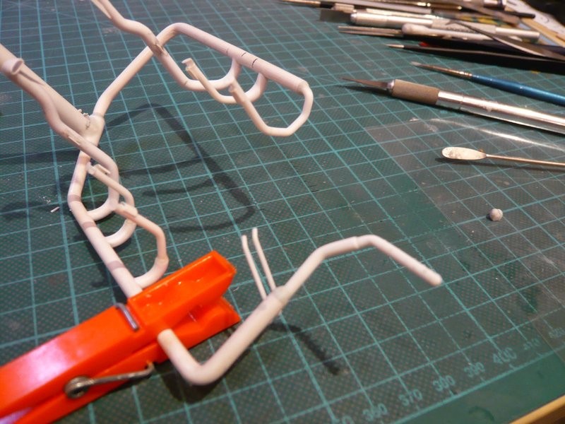 On the occasion I have also installed one of the two 9'' transitions, for what I had to insert the ring line again into the shaft, which however against expectation has worked, also without removing the SRB Supports. 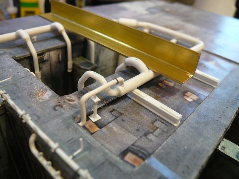 Now everything has only to dry, then the transitions still can be reworked somewhat. 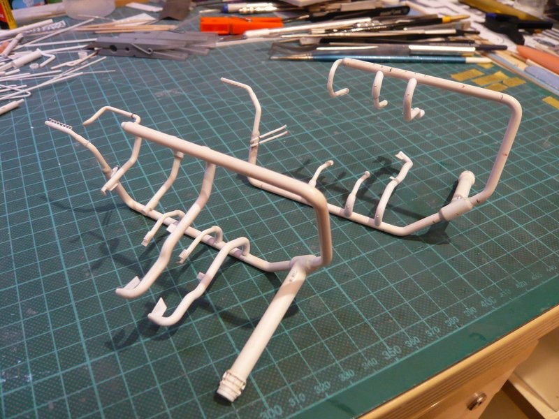 That's it for today.
__________________
Greetings from Germany Manfred Under construction: Launch Pad 39A with Challenger STS-6 (1:144)
|
|
#1259
02-03-2017, 12:47 PM
|
||||
|
||||
|
Hello everybody,
in the meantime, the modeled transitions have been carefully plastered on both pipe frames, using different tools for grinding to reach to the respective points. 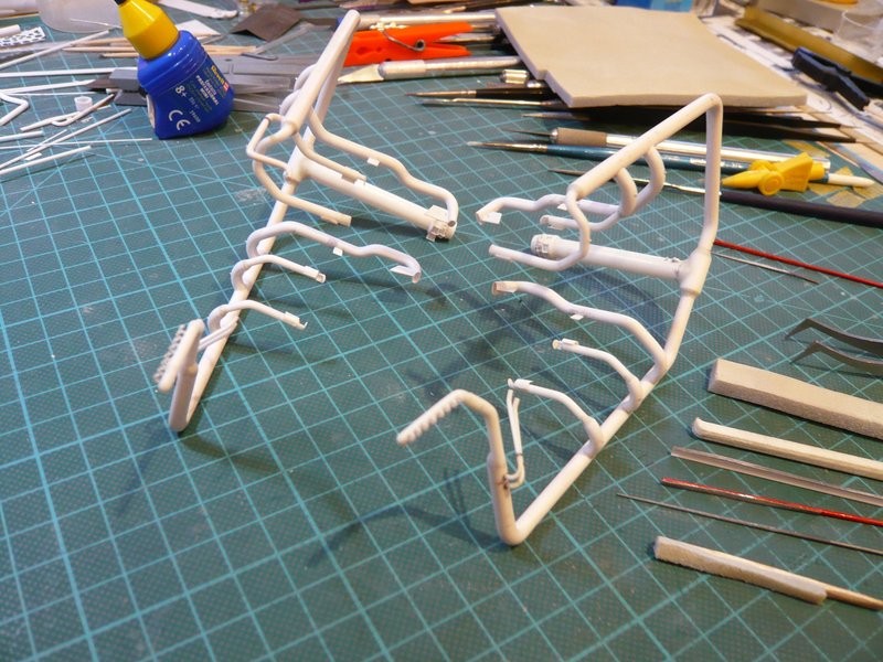 These were for the bigger roundings beside normal grinding sticks also again my handmade small sticks as well as fine files and especially grinding sponge (Tamiya-2000). Since the grinding sponge adapts particularly well to the contours, I have glued a small sponge stick from a narrow strip and a balsa stick, with which one can carefully grind around the transition without producing unsightly nicks. 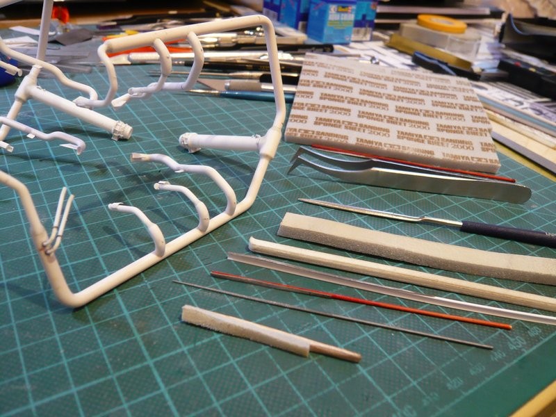 Since hardly any rework was required on the 18'' outlets, existing unevenness were eliminated with a thin needle file (Ø 1.0 - 0.5 mm). Now also the other 9'' transition on the ring line behind the LOX-TSM could be glued, whom I had to give especially care while further handling, since the glue point with Ø 1,5 mm is highly sensitive and extremely fragile.  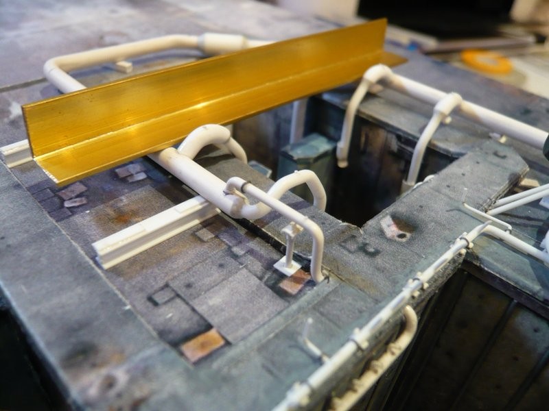 The thin support rods under these transitions can only be glued at the very end, because their support webs are simply too narrow and would hardly provide support. Then the other two-part clamping ring came next into line. 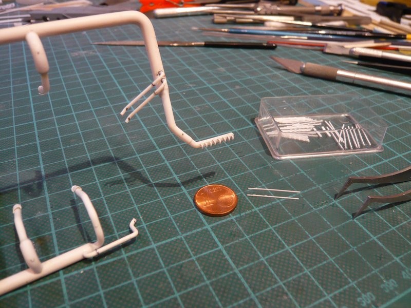 After I had marked the position of the screw connections with a tape strip, 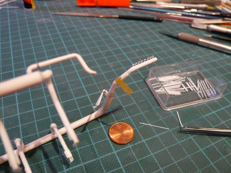 the clamping ring was glued step by step. 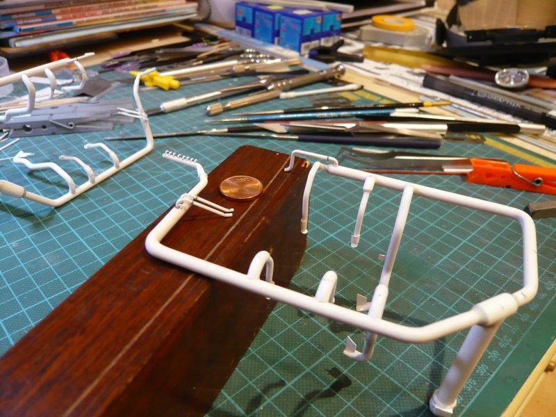  Thereby the two ring lines are now finished, so that now the 28 clamping rings can be glued, which certainly will become a stressful affair. 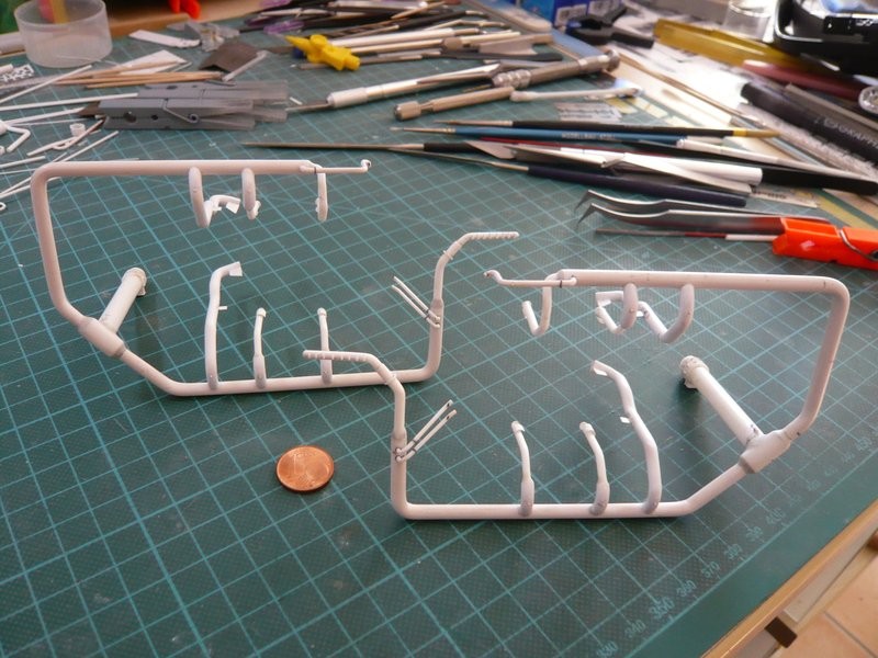 At first, however, the positions had to be marked, for which I have used a small tape template, which was very helpful. 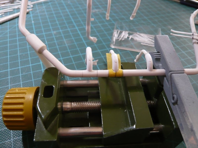 And now my drawing of the ring line behind the LH2-TSM came again into the game, 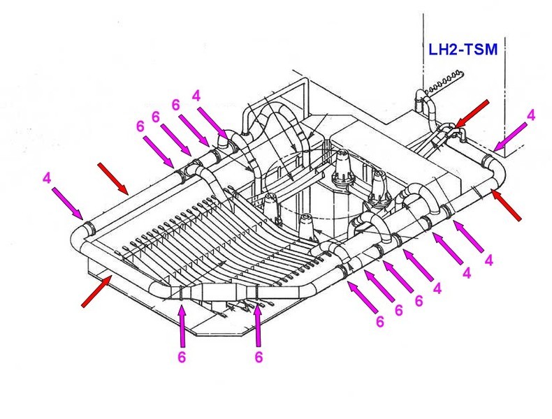 by means of which I marked the position of the six-part (green) and four-part tensioning rings (blue) on the ring line, therewith nothing can get jumbled, because the arrangement of the clampingg rings on the ring line behind the LOX-TSM looks a little different. 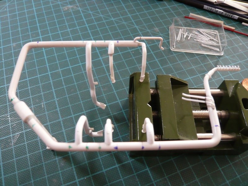 So it can now finally get started with the clamping ring orgy, of which I already a bit dread. Because this time I have to go back again to the CA, because with MEK the disaster would be pre-programmed, if you can remember, long, long time ago ...  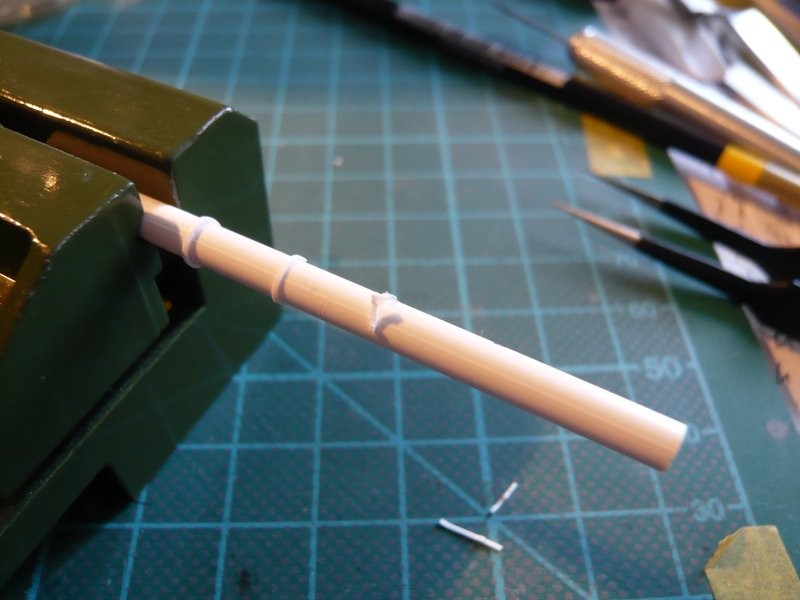 The important thing is a secure holding of the ring line, in order to be able to position the clamping rings correctly, because the first contact has to be fixed straight away, especially since correction is extremely difficult. Because if the starting point does not glue, one has to clean the glue point again, because on the old CA strangely enough no new CA glues. But today I do not start anymore, because now our dog wants to go outside ...  Bye for now.
__________________
Greetings from Germany Manfred Under construction: Launch Pad 39A with Challenger STS-6 (1:144)
|
|
#1260
02-05-2017, 10:40 AM
|
||||
|
||||
|
Hello everybody,
now for the gluing of the first clamping rings on the ring line behind the LH2-TSM, which has proved to be the expected tricky affair to do. As can be seen in the picture, it started with four four-part clamping rings behind the TSM first, followed by five six-part rings. At that I proceeded during gluing in such a way that I first glue only the first screw connection on the underside of the ring line with CA, and the remaining ring then stepwise until shortly in front of the last screw connection, where the end of the strip is glued fitting exactly connecting with the first screw connection after cutting off the overhang. In order to allow the ring to be attached better when gluing, it is advantageous if the starting point behind the first screw connection is carefully pre-rounded. But already the start was a complete flop, because the first screw connection was broken off, which has surprised and frustrated me of course. I can only explain it to myself, that the strip has been scratched too much during the chamfering of the screw connections and thus unfortunately had a predetermined breaking point. This can happen already, but should not throw me off track, which is why I then went on still more cautiously. So I have glued the barely 1 mm long tiny screw connection and behind it then the remaining clamping ring, which still looks quite neat. 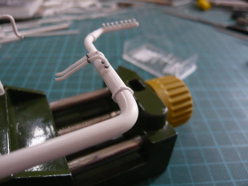 And in the same way followed the next two clamping rings, but unfortunately again not without malheur. Because as I had already emphasized, one must clamp the ring line somehow, so that one has free hand, in order to position the clamping ring exactly and to press it smoothly. I had the ring line in my little vise already, but the inner 18'' outlet layed obliquely at the vise, and during the careful pressure of the clamping ring there was suddenly a quiet click, at which I already suspected something bad ...  And after clamping out of the ring line I got prompt the receipt, because the outlet had done its name all honor, and had gone out off the ring line, by which I was badly served and needed fresh air.  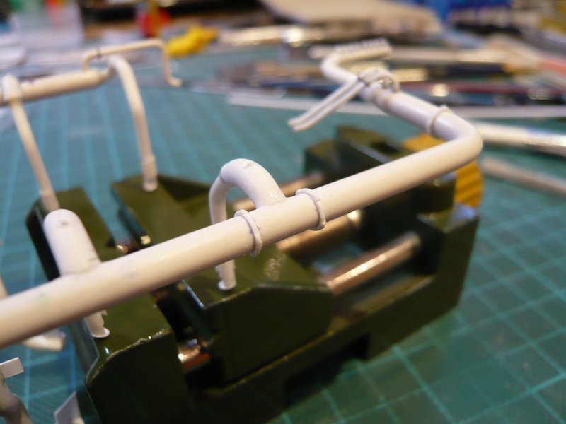 Afterwards, I have the ring line again in the SRB chamber inserted and the outlet again glued on. And this gave the opportunity to try out the supports just under the first clamping rings. 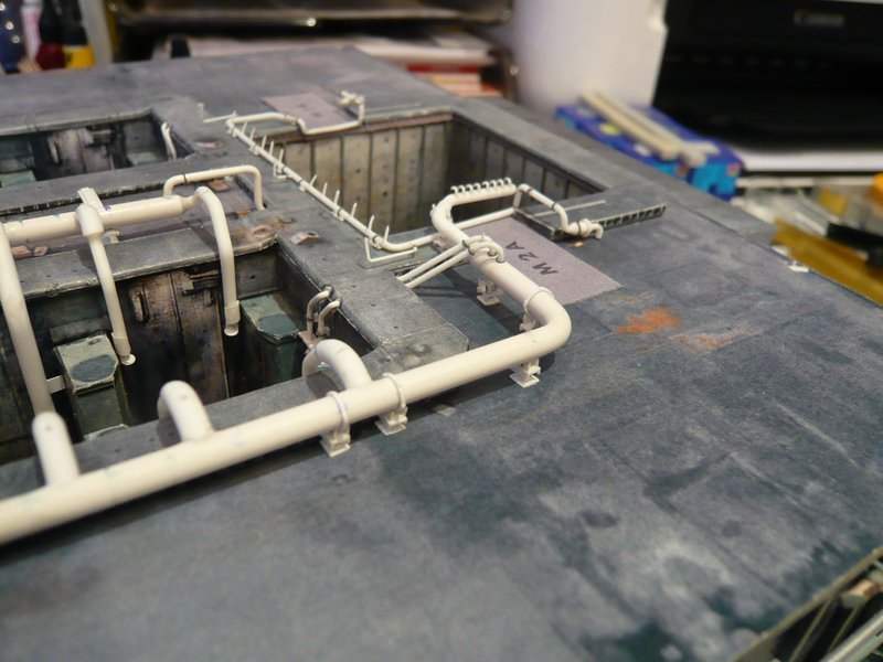  Now I just hope that the next clamping rings do not create similar difficulties and are good.
__________________
Greetings from Germany Manfred Under construction: Launch Pad 39A with Challenger STS-6 (1:144)
|
 |
|
|


 Linear Mode

