


|
|
|
#741
 03-21-2015, 12:04 PM
|
||||
|
||||
|
To say the very least Spacrunner you attention to detail is way beyond the zone. It's one thing to build the model to scale but to make it look like the real deal with all the wear and tear and amazing to me. What your doing here really blow my mind. Not that it take much any more by so many of the members here at PM. What your doing with this model is really taking model building to the extreme. I really love your photos. Thank you very much for taking us all on this trip of yours. I would say fantastic but even the word doesn't seem to fit well. I'll have to go hunt down another word. Thank you very much for sharing. wc

|
|
#742
03-21-2015, 06:14 PM
|
||||
|
||||
|
Great as always!
__________________
PAPERENGINEER Designs in progress: -C-2A Greyhound -Br.1050 Alize
|
|
#743
03-21-2015, 07:01 PM
|
||||
|
||||
 This work as always is beyond words. Only bulging eyes and an open mouth is the only expression that will work here. This work as always is beyond words. Only bulging eyes and an open mouth is the only expression that will work here.
__________________
Non Sufficit Orbis-The world is not enough.
|
|
#744
03-22-2015, 01:24 AM
|
||||
|
||||
|
Thanks guys for your kind words of praise and your continuing interest in my work.
 This encourages me to persevere and continue to go this long and winding road.  
__________________
Greetings from Germany Manfred Under construction: Launch Pad 39A with Challenger STS-6 (1:144) Last edited by spacerunner; 09-26-2016 at 10:48 PM.
|
|
#746
03-25-2015, 11:32 AM
|
||||
|
||||
|
Thanks G1 for the nice words.
Hi there, before I started with the second pipe pair, I still have experimented a bit with the mountings of the pipes. Unfortunately, the photos of these pipes are not sharp enough to see the details more closely. But I mean, there are holding clamps with which the pipes are connected to the brackets on the rear wall. The middle clamp is clearly a clamping ring for detachable connection of pipes, as can be seen in many places of the thicker SSWS pipes. Perhaps this middle clamping ring is only a sleeve.  And this I have tried to indicate by a tape roll and a sleeve made of aluminum foil, whereon the clamping ring is stting, made of lead wire (0.2 mm). But the handling is already at a single round profile a pretty tricky matter, 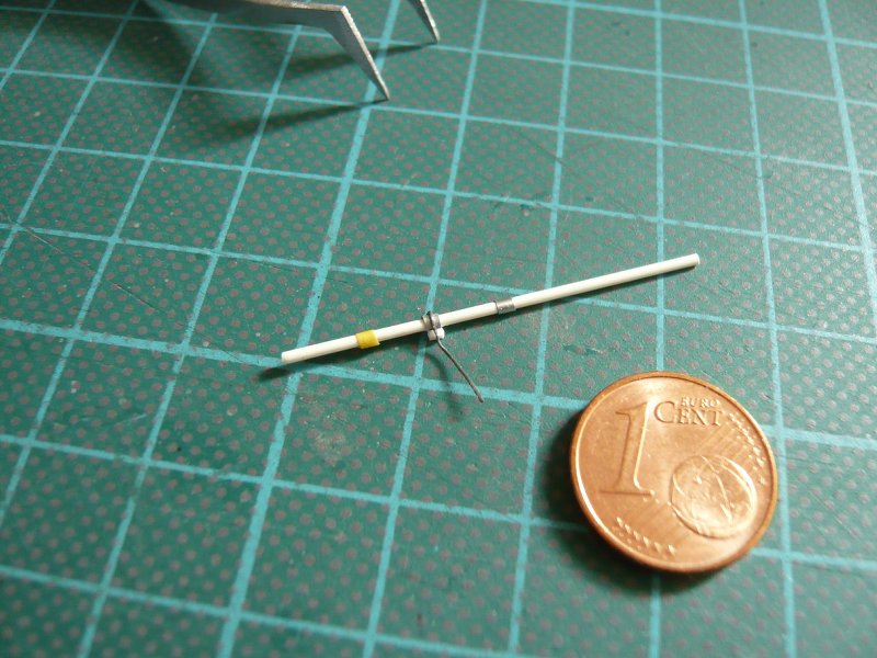 let alone the finished pipes pair.  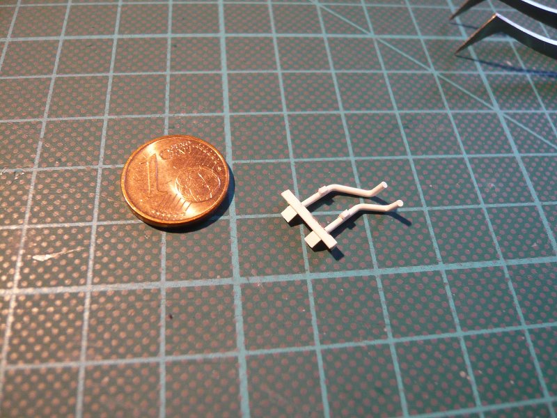 Therefore, I have decided to omit the sleeve and to indicate only the clamping ring. 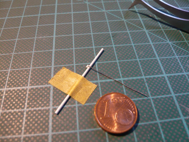 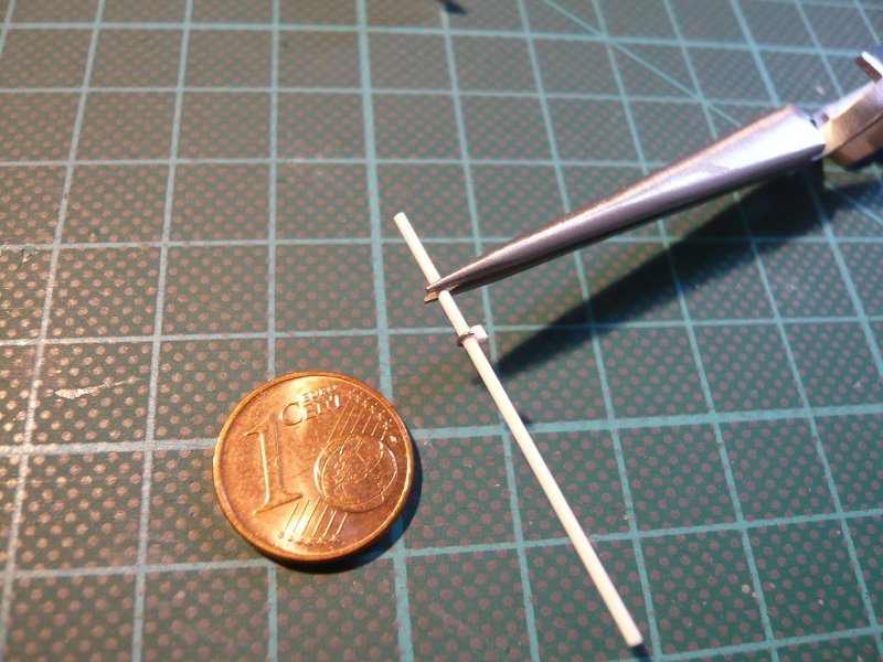 For the small brackets I finally used tiny T-Beams made of Evergreen strips, 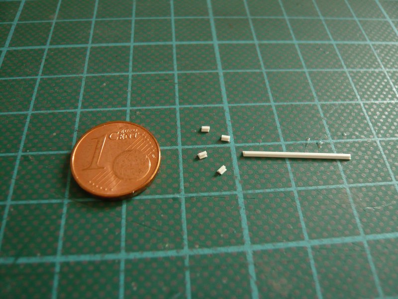 which then end up looks like this.  So far so good, and therefore, now to the construction and assembly of the pipes in the other hole in an analogous manner. 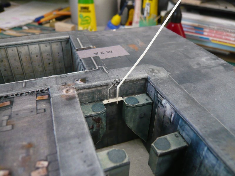 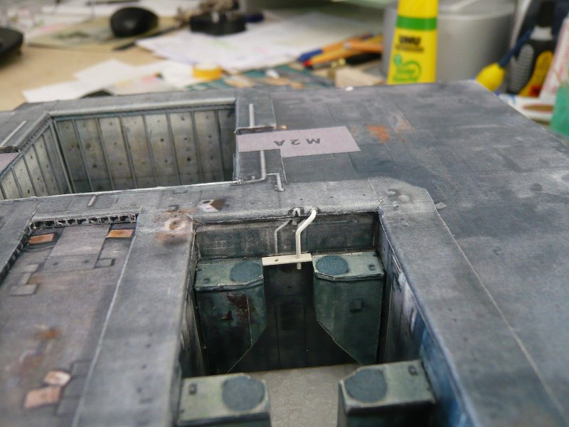 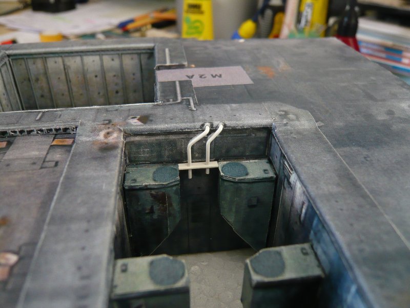 And so back to the trickier detail steps in the installation of mini-brackets, baffles and clamping rings in the following pictures. 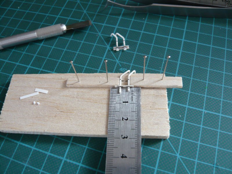 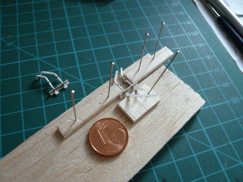 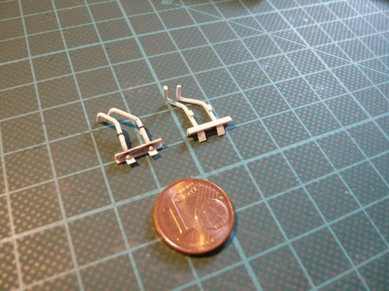 The conclusion was again the stressful attachment of the lead wire, since gluing must be done with CA. If namely the first gluing is holding not immediately, there are problems, because then you have to remove the CA again only what is in these mini-contacts really crude. And then the excess wires must be removed with the cutter. It can happen, that the wire ring redissolves or breaks off the bracket.   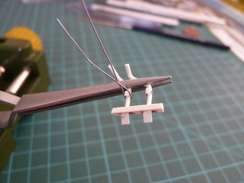 But then the second pipes pair was finally made,  andthe pipes look like after the final fitting in the SRB holes, 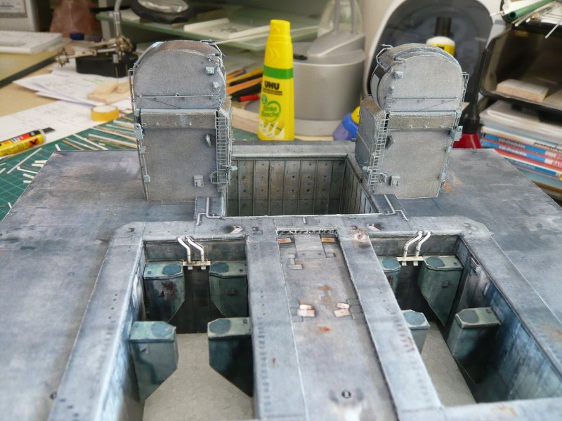 which can be painted now.
__________________
Greetings from Germany Manfred Under construction: Launch Pad 39A with Challenger STS-6 (1:144) Last edited by spacerunner; 09-26-2016 at 06:22 AM.
|
|
#748
03-26-2015, 03:16 PM
|
||||
|
||||
|
Thanks dhanners for your compliments, that would be too much of a good thing for me.

__________________
Greetings from Germany Manfred Under construction: Launch Pad 39A with Challenger STS-6 (1:144)
|
|
#749
03-26-2015, 03:19 PM
|
||||
|
||||
|
Hi there,
so that the paint is also worthwhile, I will scratch build the next SSWS pipe. It is this line here, which runs around the SSME hole, as you can see here on the templates of the Blast Shield covers from the Paper Kit.  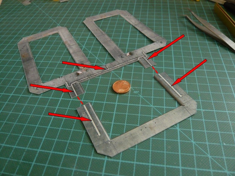 Thereafter, this ring line should obviously run through the TSM's, which is not true, as you can see in the following image. Then the supply lines come in front of both TSM's from the MLP-deck and then branch into a strand with several nozzles along the hole, and down into it. 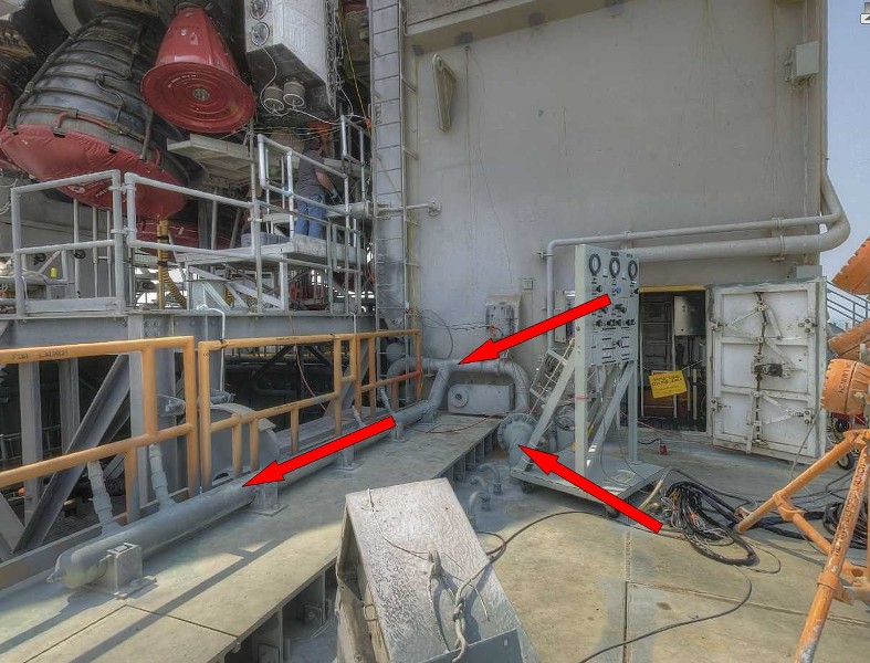 Source: NASA In this picture you can see the rest of the line that runs along the top of the hole on the inside of the TSM's along and then again to the top and around the hole. 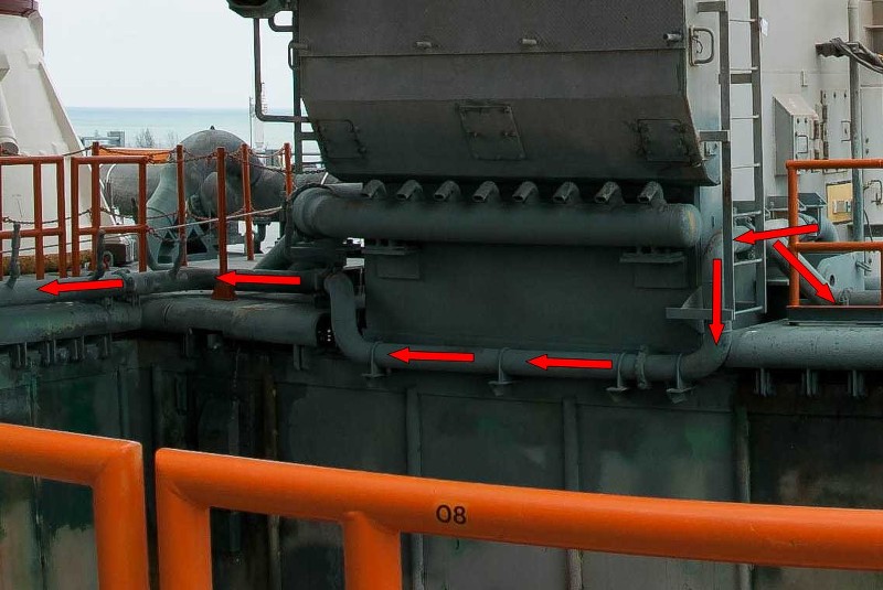 Source: NASA As you can see in the pictures and panoramic shots, this rear part of the line over the entire length has also a series of water nozzles. 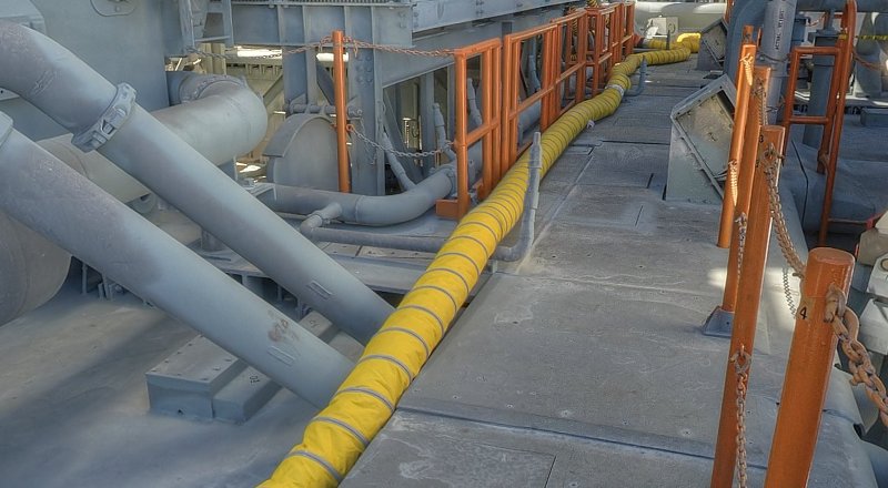 Source: NASA So much for this line, now I need only to determine the dimensions of the associated supports and nozzles, and then I can start with the scratch building. The diameters of the pipe and water nozzles correspond with 1.4 mm and 0.5 mm with the already finished nozzles pipe on the rear wall. 
__________________
Greetings from Germany Manfred Under construction: Launch Pad 39A with Challenger STS-6 (1:144) Last edited by spacerunner; 09-26-2016 at 06:23 AM.
|
|
#750
03-31-2015, 05:10 PM
|
||||
|
||||
|
Hi Guys,
before continuing with these pipes, I have to correct something my last post.  The presented piping system is not a part of the Sound Suppression Water Sytems (SSWS), as I had previously thought. As I have discovered these pipes belong to the Fire Suppression System which is activated as a result of problems with the SSME main engines and means a launch cut off (Redundant Set Launch Sequencer - RSLS - abortion) at the last moment immediately before the SRBs are ignited.  I came across it in the evaluation of the reference material for the determination of the dimensions of the pipes and water nozzles, so among other things, when viewing photos and videos of SSWS tests. One can always only see the larger SSWS systems in the three exhaust holes and the Rain birds in action, but never these pipes of the SSME hole, but would not surprise, considering the haze of the massive volume of water.  But then I reminded me of pictures, especially where the fountains of water sprays were seen on both sides of the front hole in action, but just did not know where I should be looking. After a longer investigation of photos and videos from launch aborts I've then been able to find and hit the STS-41D, in which such a RSLS abort took place for the first time. Similar aborts there were also in the missions STS-51-F, STS-51, STS-55 and STS-68.In this STS-41D-Video (from 4:48) one can see these water fountains in front of and behind the LOX-TSM after activation of the system.  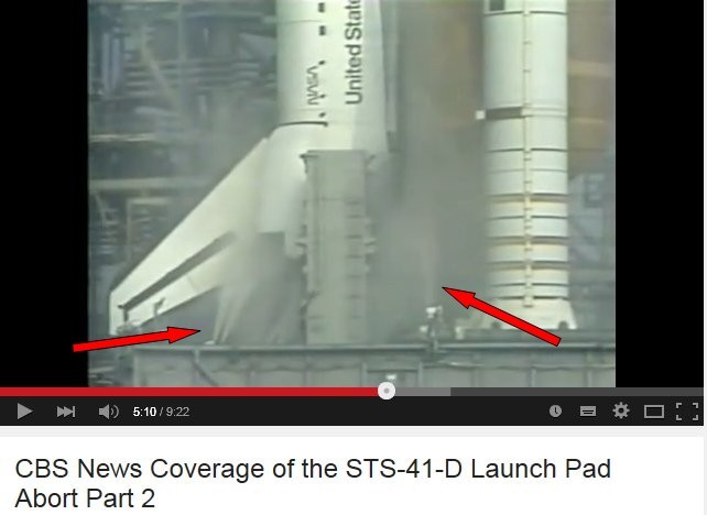 And after this very interesting technique escapade again to practice and first again to the laborious determination of the required dimensions. Here is my first time rough sketch with all sorts of sizes/calculations and positions of the pipes with spray nozzles from the Blast Shield on the back wall to the front of the SSME hole, 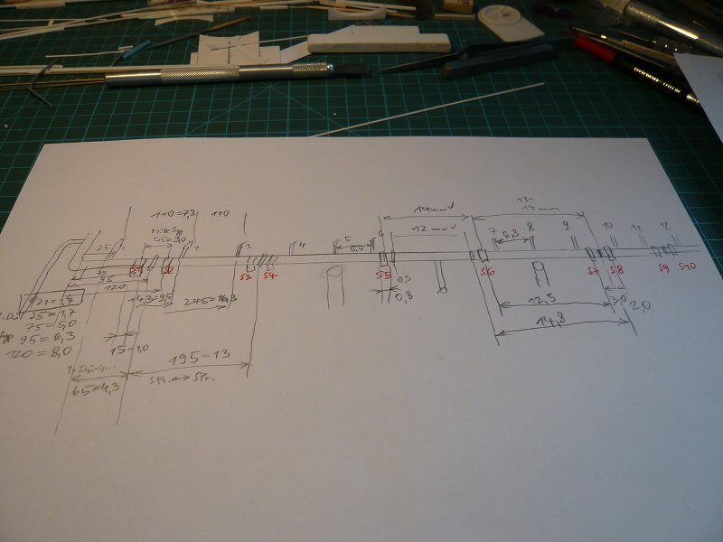 and here is my scale drawing with the supports (green), clamping rings (red) and the 25 spray nozzles (black), but this is hardly visible at this resolution. 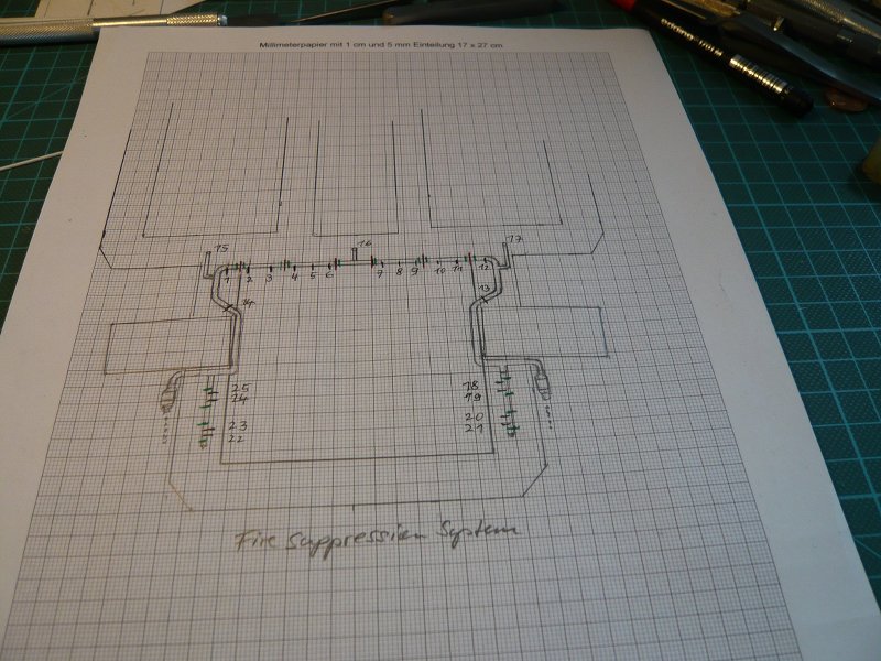 And here are the materials that I want to use, 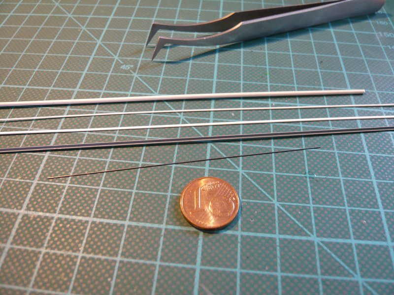 round profiles Ø 1.4 mm and 0.5 mm for the pipes and nozzles on the Blast Shield, an Evergreen strip 0,75x0,38 mm for the supports and 0,2 mm lead wire for the clamping rings and brass angle profile 1x1 mm for the supports below the TSMs. That's it for today, and tomorrow I will throw myself then boldly into this pleasure.
__________________
Greetings from Germany Manfred Under construction: Launch Pad 39A with Challenger STS-6 (1:144) Last edited by spacerunner; 09-26-2016 at 06:30 AM.
|
 |
|
|


 Linear Mode

