


|
|
|
#561
 01-13-2019, 03:26 AM
|
||||
|
||||
|
Quote:

|
|
#562
01-13-2019, 03:32 AM
|
|||
|
|||
|
The 1/24 base
Dear all
So I have been thinking about the "base" for the 1/24 model. I have been looking into an apollo era MLP, keeping open the fantasy of one day having a 1/24 MPL, 1/24 crawler and 1/24 LUT to go with the 1/24 Apollo Saturn V. However I am not a designer and can not find kits of the above to enlarge to this size. So for the moment I am not including a "base" as part of this build. So the build is getting close to finish now Regards Kevin
__________________
Normally the most advanced tech I use is a pencil.
|
|
#563
01-13-2019, 07:14 AM
|
|||
|
|||
|
Alphonso has an Apollo Era crawler. A 1/24 crawler would be... impressive. There is a 1/480 LUT/MLP http://papermodelingman.com/lut480/cs.html but it'd take a lot of work to scale it up that size.
Not to mention the gymnasium you'd need to display it 
|
|
#564
02-05-2019, 03:45 PM
|
|||
|
|||
|
Quote:
Regards Kevin
__________________
Normally the most advanced tech I use is a pencil.
|
|
#565
02-05-2019, 04:26 PM
|
|||
|
|||
|
Pipework for J2 engines on stage 2 for 1/24 model
Dear all
So moving onto stage 2. I decided to do all the pipework for the J2 engines. Since these pipes are in the updates parts there are no instructions as such so I found using the photos of heroicrelics.org: Relics of the Heroic Age of Manned Space Flight the best things to work from. For example photos like this 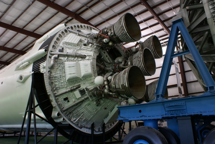 So first some long pipework was formed which was then angle trimmed to meet with the thrust structure   Next was the "bend section" which was rolled but not glued. Then inserted into the main pipe to get the correct diameter fit (as shown). The other end of the bed section was checked to be "easily " smaller diameter than the LH2 pipe of the engine it would eventually go into.    Next the engine was located onto the thrust structure and the main pipe glued into position  When gluing this pipe i had a choice. To run vertical and NOT be in line with the fairings that would eventually go on the outside of stage 2 or to run at an angle and be in line with the fairings. As you can see in the picture from herorelics on the real Saturn V the LH2 intake to the J2 engines are in line with the fairings. The reason for the difference in the model is the J2 engines do not match with the cross member (it is a bit of a compromise attaching the J2's to the thrust structure). So in the end I went for vertical pipes. The the bend section was glued into place. I really did not get a "good bend" so decided to cover things up with holding brackets   Then to finish off an engine I extended the LOX pipe into the thrust structure    For the centre engine I made the pipes that are on the cone part of the thrust structure which go through the holes in the structure. I found using the "widest" of the bracket pieces useful here to hide the bend area.  However I did not run any piping across the cross beam to the centre engine since I was not able to make a decent pipe bend into the engine inlet pipes. So instead I just extended the LH2 and LOX straight into the thrust structure. Then I did the remaining engines. Here are some photos of the finished pipe work.     So that is all the thrust structure and engines of stage 2 finished. So all that remains for stage two are the umbilical tunnel and fairings on the main body of stage 2. Regards Kevin
__________________
Normally the most advanced tech I use is a pencil.
|
|
#567
02-08-2019, 03:40 PM
|
|||
|
|||
|
Quote:
Regards Kevin
__________________
Normally the most advanced tech I use is a pencil.
|
|
#568
02-08-2019, 04:15 PM
|
|||
|
|||
|
Bit more on 1/24 stage 2
Dear all
So the next thing I worked on was the umbilical tunnel on stage two. The design is different to that used by Greelt on stage 1 and to be honest I did not fully understand the instructions that went with the stage 2 design. For this reason I decided to use the Greelt design for umbilical tunnel. So (just like for stage 1) there is the internal strengtheners cut, folded and glued   followed by the outer skin of the tunnel (less the end cones)   Then the skins are attached to the strengtheners, remembering (just!) to get the correct parts at the "pointy ends"   Next comes the magnetic paper  And then the end cones   The last thing to do is add the ferrous paper to the rocket body. However before doing that I decided to make the fairings for the fuel pipes. As with the umbilical tunnel, I decided to make the fairings using Greelts method for the umbilical tunnel for stage 1. It was straightforward to modify the printed parts for this method. So it was first the support structure, then the outer skin and then joining them    Then I added the triangular base ends   They did not feel right but I could not see anything wrong so I cut the magnetic paper next   Then cut out the end cones  and they did not fit! I had made an error in calculating the radius of the outer skin and made it too big! More to follow Kevin
__________________
Normally the most advanced tech I use is a pencil.
|
|
#569
02-08-2019, 04:26 PM
|
|||
|
|||
|
bit more on 1/24 stage 2 cont
Dear all
So after getting the size wrong on the outer of the fairing a bit of "surgery" was performed followed by some "crushing" into shape of the support structure and the a new outer "grafted on".     It seemed to look okay in the end so I then put the end cones on  A bit fortunate that I was able to correct my error! Finally I added the ferrous paper to the main part of the rocker and tried out the umbilical tunnel and then the fairings.   There are still a few more part to put onto stage two but the stage is nearing completion. Regards Kevin
__________________
Normally the most advanced tech I use is a pencil.
|
|
#570
02-09-2019, 12:30 PM
|
|||
|
|||
|
Slight pause in 1/24 model build
Dear all
In my local city there is a museum called the Harris Museum. I think it is a really nice building (here are some pictures of outside and inside)    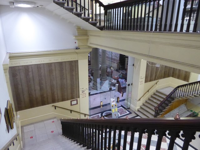 It is currently hosting the "Museum of the Moon" until Feb 24th Harris Museum - Home. I think it is a fantastic thing to see (and it does travel around the world) so if you get the chance I would encourage you to go and see it. (This site tells you where you can see it around the world https://my-moon.org/ ). The 7 metre internally lit high resolution moon is normally suspended in big cavernous areas, however because of the design of the Harris museum you can see it on different levels really close up (about 2 metres away) Here are two photos people have posted. 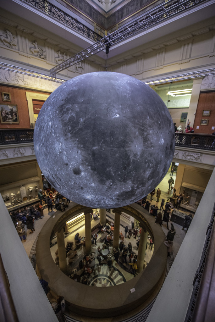 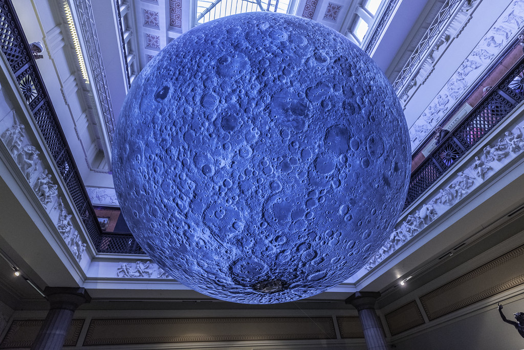 Anyway complementing the moon the museum is also hosting an exhibition about the moon landings and they asked if they could borrow the 1/24 Saturn V which I was happy to do. (They have put up the information of the designers and also the availability from John Leslie's website). I took the liberty of taking a few photos and they are below for those interested. Some full length shots    The some sections of the Saturn V     A couple along the stack   The "Apollo" section   And finally the LM "on the moon"  When I first put the model up a viewer asked where the flag on the moon was (since I did not have one displayed). I thought it was a good point. I have Ken West's "Astronauts on the Moon" model so used the flag from that and reduced it to 1/24 scale. People seem very enthusiastic about learning about the moon shots. Also that we should go back and go to Mars. When they see it is made of paper and can have a go themselves they seem quite excited. Of course I have to pause finishing off the build whilst it is at the Museum. Regards Kevin
__________________
Normally the most advanced tech I use is a pencil.
|
 |
| Tags |
| apollo, moon, rocket, saturn v |
| Thread Tools | |
| Display Modes | |
|
|


 Linear Mode

