
 |
|
#51
|
||||
|
||||
|
Very precise work. I will be watching the build
|
|
#52
|
|||
|
|||
|
Aldeb, I think I'm going to need your help for a moment.
Those two taps I'm building are kind of planted into the side of the kettle, but there is no indication whatsoever in the diagramms to where there is a pipe running... one does only see a pipe going down a bit and than make a 90° turn to the back, but there is no indication where it goes into the side tanks. I've watched your 3D model on the forum, but on those renders it's not clear either, probably you have better renders (I'm sure you have, knowing your level of detail), showing exactly where every pipe goes and connects to. Also I have a second question about the sanding pipes... in this steam engine those pipes go a lot of meters without any support at all, while on my real life engine they only go about less than 1 m and are supported by brackets about 20 cm before they reach the end... BTW... one of the sanding tubes got loose today, and I hadn't even noticed it, lol...
__________________
On the Bench : USS Maine |
|
#53
|
|||
|
|||
|
Indeed I looked up modelik and it looks to me that the water pipe diagram is pretty sparse. Maybe you can look up their Freudenstein loco, which has a very similar looking system. But that's my guess at least. you can see the water pipe layout here
http://www.kartonbau.de/forum/schmal...les/t27153-f9/ It should probably look something like this  The two water pipes from the boilers always have to connect to the injectors. I think the pipe going down just ends in the floor (normally it should connect to the two water tanks). These injectors are pretty simplified. A live one might look like this http://i1308.photobucket.com/albums/...ps78471b4c.jpg The pipes from the boiler carry water. The pipe going down goes into the water tanks (or tender in other cases) while the last pipe going down is a sort of steam exhaust, so it doesn't really go anywhere As for the sanders... i'm not really familiar with this loco. but i guess the sander pipes are left dangling here just because of scale reasons Last edited by Aldeb; 09-03-2014 at 04:33 PM. |
|
#54
|
|||
|
|||
|
Ah, ok, it seems I must have misunderstood or misinterpreted your previous post, I kind of understood that the pipe ran from those taps directly to the side tanks (still to be installed, and not yet ment to be made).
The "fireplace" in your image looks exactly like the one in my little machine, except for the floor that is, mine will be "metal" instead of "wood". Thanks you for your expert imput. Concerning the sanding pipes, I gues, I'll just add some wine lead strips where it seems logical to support them (based on modern day machines). Concerning the things being simplified..., lol, that suits me very fine, for a newby when it comes to paper steam engines 
__________________
On the Bench : USS Maine |
|
#55
|
|||
|
|||
|
Just a (very) little progress yesterday.
The two safety valves, the second tap (not in the photograph) and a lever that goes in the greenhouse : 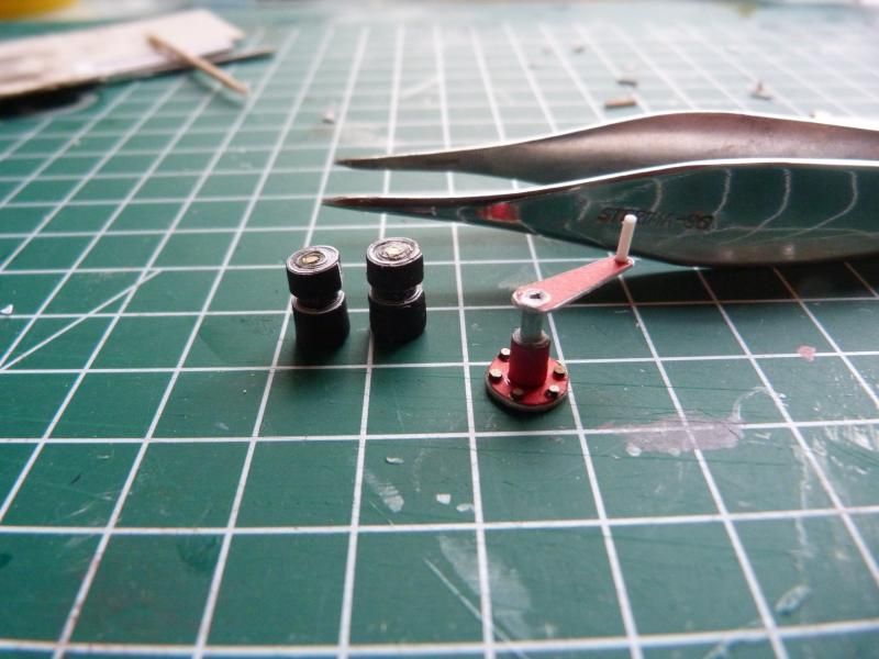 First mistake found in the kit (at least the first one that isn't mine, lol) : 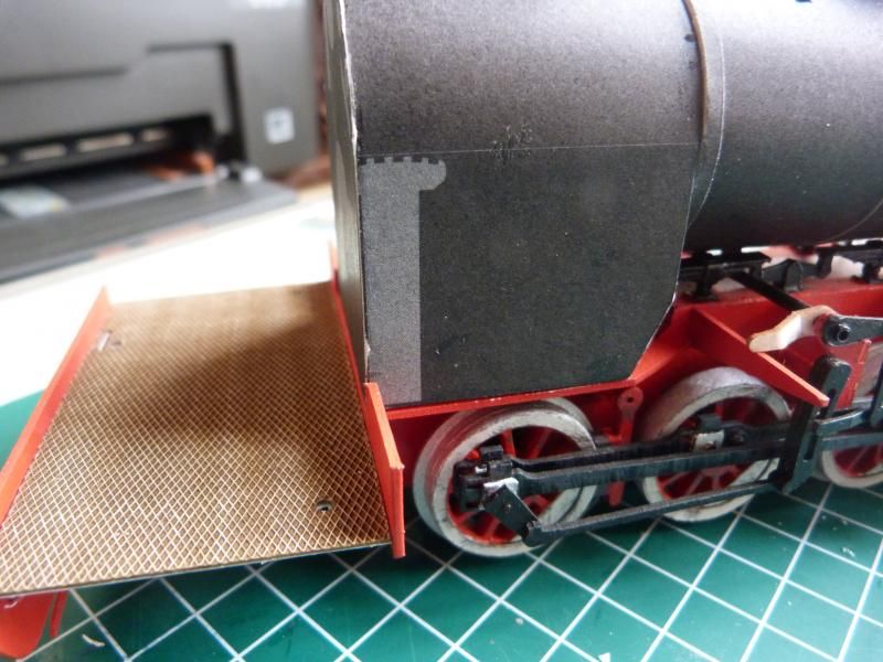 If you place that large lever (I think it's the equivalent of a gearshift, since it will be connected to drivetrain) on the grey marking, you'll get in trouble as soon as you want to fix the boiler onto the frame : 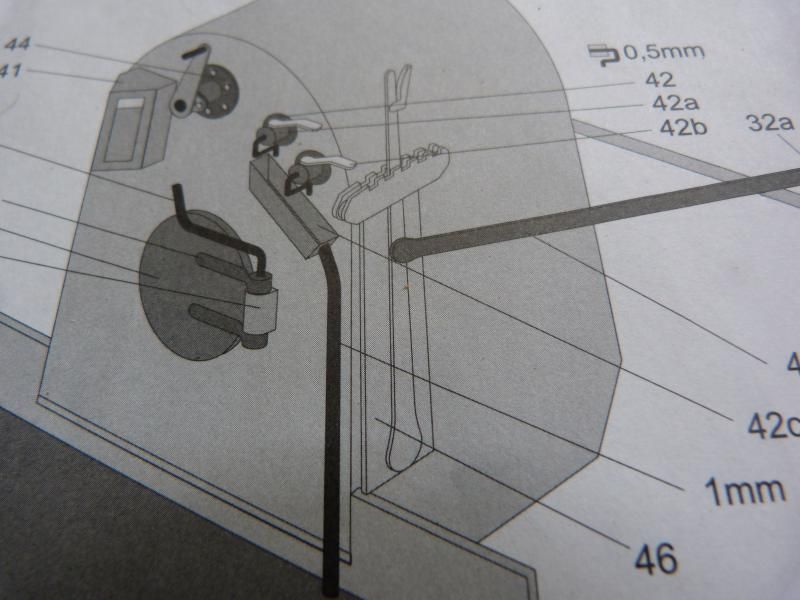
__________________
On the Bench : USS Maine |
| Google Adsense |
|
#56
|
|||
|
|||
|
Yes, there is at last a little progress done on the "Las" (btw anyone who knows why it's called "Las" ?(meaning "Woods" or "Forest")).
The front of the boiler : 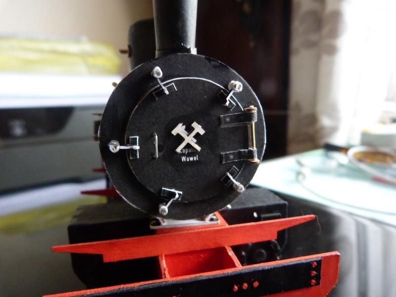 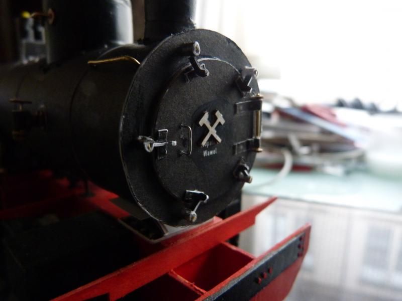 And the first two handles (is that correct ?) : 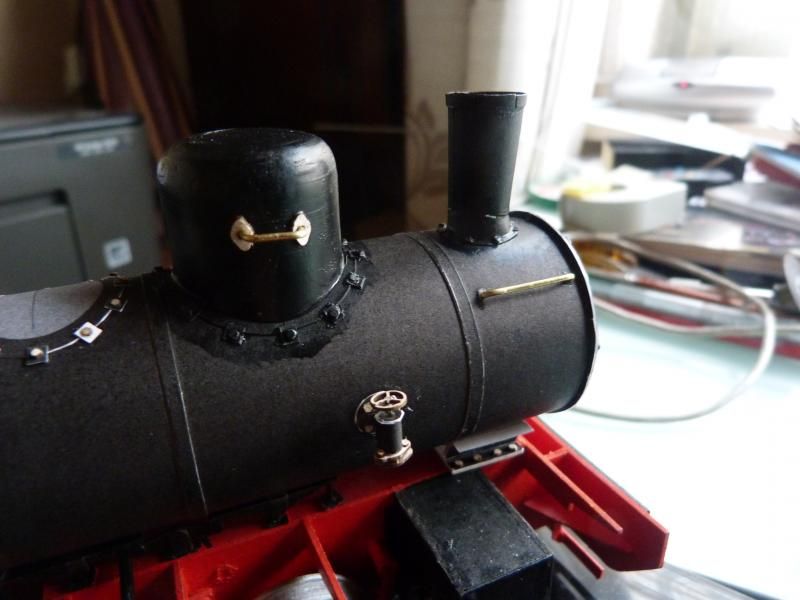
__________________
On the Bench : USS Maine |
|
#57
|
|||
|
|||
|
The more appropriate word for handle would be "grabiron"; however the word handle should suit if you're more comfortable with that.
The front boiler clamps (?) are very realistic. Did you form them and the grabirons from wire? What you posted today looks very good. If I didn't know better I'd say you were posting pictures taken of the real thing in a museum somewhere! Your work is that good.
__________________
This is a great hobby for the retiree - interesting, time-consuming, rewarding - and about as inexpensive a hobby as you can find. Shamelessly stolen from a post by rockpaperscissor 
|
|
#59
|
||||
|
||||
|
comeing along nicely
__________________
David........... Paper modelling gives you a happy high. currently building. c GAZ 51 ALG 17, wagon 111a. unex DH411 excavator and spitfire Mk 9 |
|
#60
|
|||
|
|||
|
Well, here I am again with a little update on the "Las".
I added the safety valves, the sanding dome, and the bits in steeringhouse... and a bit of paint while I was ad it  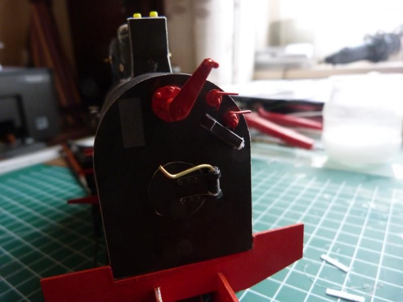 As you can see, I used two beads to give a bit of shape to the valves : 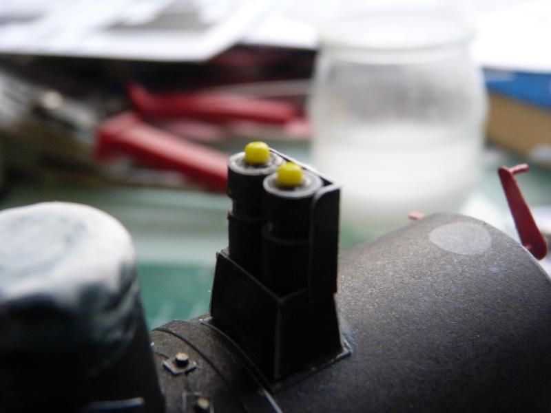 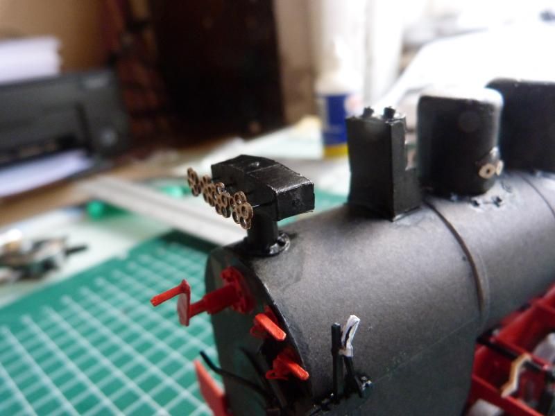 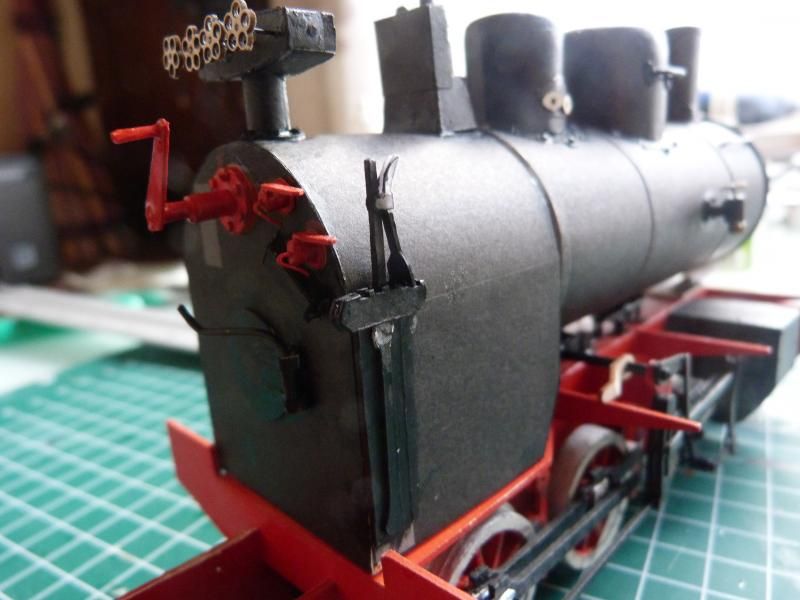 A bit of paint here and there, jut to see how it will look like when everything will be painted : 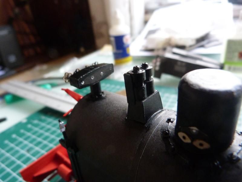 And I also started on the "house" : 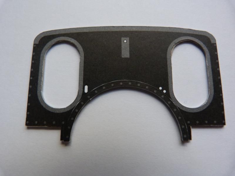 A dry fit of the bunkers and the front : 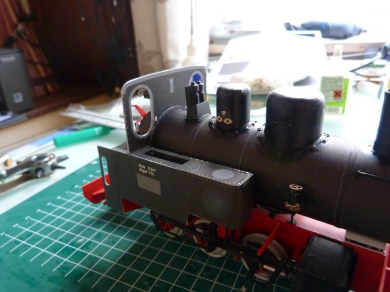
__________________
On the Bench : USS Maine |
| Google Adsense |
 |
|
|