
 |
|
#21
|
||||
|
||||
|
Hi Don,
And many thanks for those photos. The second one is just what I was looking for. Not only does it show the routing of the anchor chain through the capstan from the chain locker it also shows a second piece of deck reinforcing plating that is on the opposite side of the capstan from the single one provided. I can use the single piece that is in the kit for that reinforcement and I will have to dream up my own Chain Locker opening parts. There is also a raised part that goes around the hole where the anchor chain descends to the anchor opening in the side of the hull. I am also wondering about the way things are laid out in the photo. It would appear that the anchor positioning on the model is the reverse of how the real ship was laid out. Perhaps the ship is modeled as she was after having her original bow blown off, the camo paint job being the big tip off there. Unless I can come up with a photo of the ship with her camouflage colors in place, that being how she appeared after suffering her bow transplant, I probably will never know. But it is just what the doctor ordered as they say!
__________________
Jay Massey treadhead1952 Las Vegas, NV |
|
#22
|
||||
|
||||
|
I will keep on the lookout for images specifically of Selfridge post-repair.
I had to do a rather hasty search. I have an on-line USAWC forum beginning tomorrow and the essay for the current course (Department of Defense Organizations and Processes) is due soon, so I spent much of the day fielding student questions. Searching for Porter class images was a nice break. I'm really glad that the image was at least partially helpful. Don |
|
#23
|
||||
|
||||
|
Hi Don,
It, at the very least, showed me the proper arrangement of the anchor handling hardware which is what I was after.  That the model has the order reversed is okay for the moment. I can handle dealing with it like it is. However, rolling up all these tiny cylinders to add to the decks as line handling bits may drive my trolley off it's already somewhat questionable tracks! :D 
__________________
Jay Massey treadhead1952 Las Vegas, NV |
|
#24
|
||||
|
||||
|
Hi All,
I managed to get a little more work done to the Selfridge today. I worked over the anchor handling area on the bow, adding a couple more details and the anchor chain. It is some generic brass chain that I got from Model Expo a while back. To change it from the bright brass color to black I used some "Blacken It", a commercial product that is also available from Model Expo just for such things. It only takes a few moments of dunking it in the mixture, rinse it off and dry it and it is ready to install. Even if you want to paint it gray, I would still recommend using the stuff just in case the paint chips or flakes off to avoid the un-natural brass color. I started adding the forward deck house using the kit supplied parts. Part of the beauty of card models is being able to print off multiple copies of the pages so you can use a few of the details like hatches, doors and vents to come up with a layered look to things. By using a couple of each door and vent in the bulkhead all around it makes what would be a flat printed part pop with detail. There are also parts that are printed such as the red fire extinguisher that is a flat printed red rectangle on the bulkhead and the vent pipe between the two light gray doors that you can add with made up pieces to get a little more relief and add visual interest to your model. I used some copper wire cut down to size to represent the hinges and door latch on the doors as well. Some commercial generic ladder stock was used to go over the printed sections of ladder around the deck house bulkheads. These came from a Polish Model firm and are made by Answer Models off the Internet. 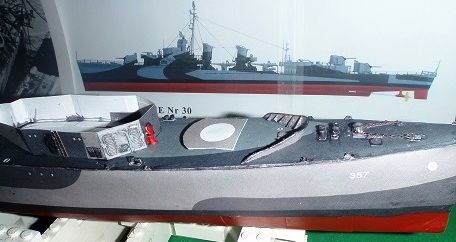 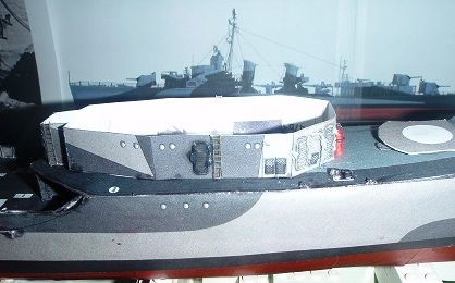 You can also see in the back ground of this photo, another picture of the Selfridge that I found on the Internet from a US Navy History site showing the top of the forward deck house to great effect from the starboard side. I shows me a ton of details that I can use to add more visual interest to my model over and above what the kit offers. Not that the kit is incomplete or anything but even commercial kits can be improved by references. I also have the Morskie Monograph BS 030 on the USS Selfridge to assist me in my detailing efforts. That is where I found that full color two sided drawing in the other photos. I have about 18 more pages of black and white drawings that show off individual sections and parts of the ship from this Morskie Monograph. 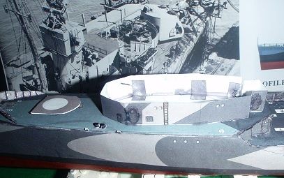
__________________
Jay Massey treadhead1952 Las Vegas, NV |
|
#25
|
||||
|
||||
|
hello Jay,
Great work! Marco
__________________
Currently Building: RN Zara 1:400 |
| Google Adsense |
|
#26
|
||||
|
||||
|
Looks terrific, Jay!
Don |
|
#27
|
||||
|
||||
|
Thanks guys,
Today I will be swapping sides with the anchor assembly so that it matches the original ship more closely. It will simply be painting over the kit provided spot on the port side and adding the hole and its' surrounding protective collar then stuffing the kit provided anchor in place. Admittedly a small improvement but one that I have actual photo documentation that proves the validity of.
__________________
Jay Massey treadhead1952 Las Vegas, NV |
|
#28
|
||||
|
||||
|
One thing to keep in mind. Many of these pre-war destroyers lost at least one chain locker and anchor to save weight. As a result, they only had one anchor and one anchor chain. A few times the second anchor was retained, but close observation shows that in those cases the chain is secured to the deck without going below. I suspect that is what you have here. Usually the port anchor was the one secured on deck as the navy tended to use the starboard anchor most of the time. That mattered when you had a group of ships anchored out - they should all be tending to the same anchor lead or there is a risk of collision. The logic is that if the starboard anchor is damaged or lost, the remaining starboard anchor chain can be connected to the port anchor, which could then be used.
The circular capstan drum is used for line handling. If the wind is pushing the bow away from the pier and the captain wants to bring the bow to the pier, a heavy line could be secured to the pier and around the capstan. Then the capstan could pull the line and the ship's bow to the pier. Below the capstan was a "wildcat." It was a circular drum that was shaped to actually fit the links of the anchor chain. It was used to hoist the anchor. There was a cutoff switch that enabled the capstan to run independently of the wildcat, but otherwise the same controls were used for both. So I suggest securing the port anchor in location using two turnbuckles, sometimes called "bosun's claw" or "devil's claw." These were welded to the deck to hold the port anchor in place, while the wildcat held the starboard anchor chain, with a single claw. When dropping the anchor, the wildcat is released to spin free but the anchor won't drop until a bosun's mate hits the claw with a sledge hammer.
__________________
Building - JSC - 1/250 SMS Emden |
|
#29
|
||||
|
||||
|
Hi Nimitz Fan,
Thanks for that bit of information of about the between the wars Destroyers and their anchor installations. I chose to use the illustration that Don provided of the USS Moffett since I am unable to find anything pertaining to the USS Selfridge specifically. It seems that most of the photos of the USS Selfridge concerning her appearance after having her bow blown off, the false bow she wore on her journey back to Mare Island and what she looked like with her late war camouflage after being rebuilt. are about all I am coming up with. I did do some more work on the forward deck house second level and up. With that done I turned my attentions to the two stacks that sat amidships. These were a little unusual in that they seemed to go from square shapes to round and oval from the bottom to their tops. The forward one had a two legged stance that I chose to fill in with some extra parts to conceal the hollow nature of its' bottom most section. Even though there are two vent stacks on either side, you can still see into the middle part. I also had to do some creative construction to get the middle section to go from the square nature to round in one 5/8's inch tall part. 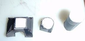 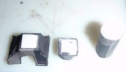 The after funnel just has two major parts from the bottom to the stack part. That leaves a single 1/2 inch section on the bottom that mounts to the top of the engineering house that starts out as a rectangle and goes to an oval shape. 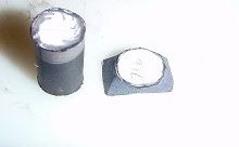 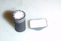 So with all these little parts as well as the two short towers that mount the quad torpedo launcher mounts added to the decks, it is starting to look more ship like. I do have the rest of the forward fire control mount to make up, the weapons from twin 5 inch forward mount, quad 40MM Bofors immediately aft of it, the 20MM Oerlikon mounts and the two quad torpedo mounts as well as a few other little details. But it is coming right along. 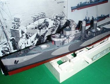 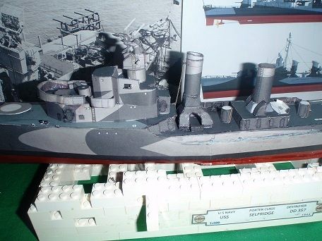
__________________
Jay Massey treadhead1952 Las Vegas, NV |
|
#30
|
||||
|
||||
|
looks great jay. I like watching other ship builds as a designer/builder. this gives some insights as to what is being done for complicated shapes and level of details to put in a kit. it also helps as a builder to find out where that damn little thingy is supposed to go. as to your revolvers, I am a collector shooter of old cap and balls too. I find the 1851 navy the most accurate when clean but go the remmys and an old rogers/spencer for match shooting. they are easier to swab out the cylinders and bore during a match.
|
| Google Adsense |
 |
| Thread Tools | |
| Display Modes | |
|
|