


|
|
|
#134
 06-20-2020, 08:46 AM
|
|||
|
|||
|
Hi
Any progress on the Bismarck? I made it years ago, destroyed it when started on the wood/copper Hachette model sold in 125 installments that now stands in full glory. Since then made Bismarck as well in 25cm steel 3d metal Piececool version. Fred 
|
|
#135
11-27-2021, 12:02 PM
|
|||
|
|||
|
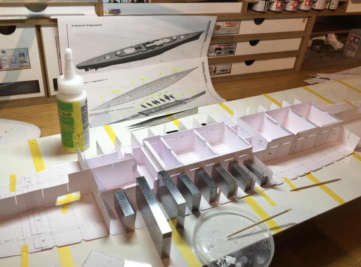
I've been on other modelling projects (plastic and model engineering which I suppose is as far as you can get from paper!
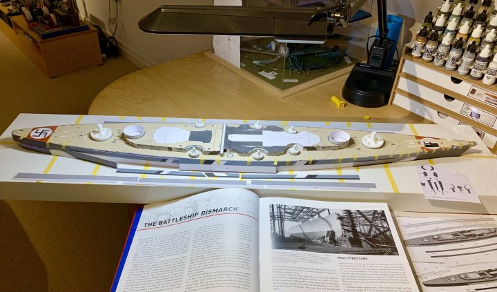
Anyway, I've started looking at the Bismarck again, and figuring out where I left it and what I was going to do next: So it's the hull sides - if these look wrong, it all looks wrong. For me this is the most difficult part of building a paper ship, and probably why I left it at this stage...too much to lose especially since this is already the second attempt. Does anyone else have a link to a full build log for this kit? I can't find one anywhere. Not sure why. I do find it extremely useful to look at other modeller's builds to get inspiration and to see how they overcame the inevitable snags with the kits. Thanks all.
|
| Google Adsense |
|
#136
11-29-2021, 03:37 PM
|
|||
|
|||
|
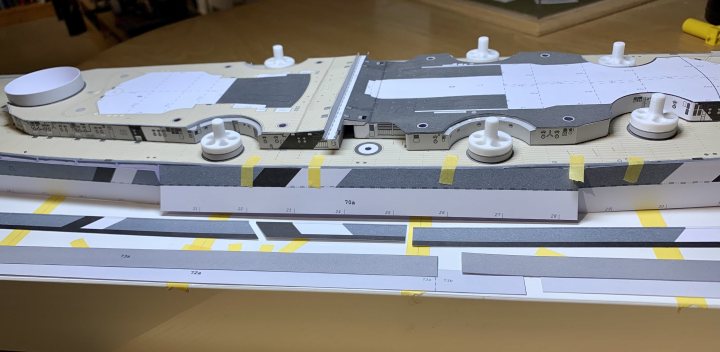
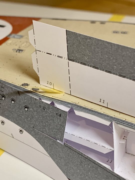
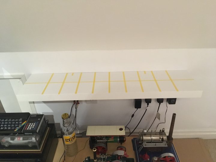
I remember now why I paused it (at the beginning of the first lockdown): The hull sides make or break a paper ship model, and this one is a monster. Multiple pieces to try to make invisible joins, doubled and tapered areas around the armour belt, and compound curves at the bow and stern:
    There are also two doubled joins towards either side of, and above the armour belt. None visible in photographs, which is odd for HMV to put steps there if its not realistic.
|
|
#137
11-29-2021, 03:39 PM
|
|||
|
|||
|
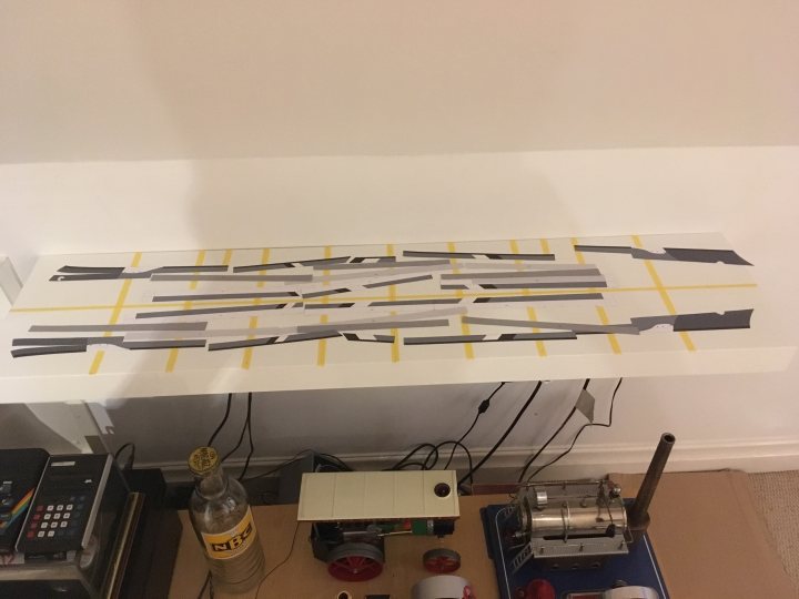
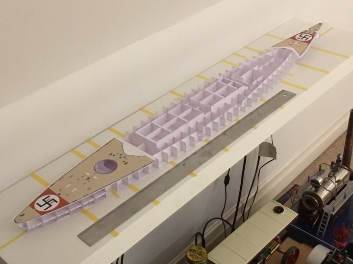
Ah, now I think I see what they’ve done. The armour belt forms a smooth curve along the waterline, but the upper hull cranks in, rather than the armour bulging out. The deck pieces have corresponding very slightly cranked sides to match. Makes more sense now, but still a bit of fettling to do to avoid triple thickness paper at the deck tab joins.
|
|
#138
11-30-2021, 10:23 AM
|
|||
|
|||
|
Quote:

|
|
#139
11-30-2021, 05:01 PM
|
|||
|
|||
|
Just re-read your whole blog since you have resumed. Brilliant work. I would say you are setting such a high standard for yourself with such a complex and lengthy build, to the point of possibly setting the bar too high considering the age of the kit.
You're doing a great job of it, I'm well impressed and watch to learn from you and already have. I'm also inspired by the fact you started completely again, since I've had a similar experience albeit with a smaller model. I completed the model, it looks great, I get admiring comments about it and enjoy explaining the extra details I added. But I know where the problems were and what I did wrong so it bugs me slightly at times, but the main thing is I completed the model. (JSC's SOLDEK - 3 - but I'm proud!!) As regards the hull sides I also know what you mean, I completed Scaldis STATENDAM before I'd discovered the reason many modellers 'tack-glue' the base plates (or keel if you wish) to glass etc. Hence I ended up with a slight banana. After the fact I glued it to glass, weighing both stern and bow down. That gave me a slight buckle on one side. Guess which side I put closer to the wall.  I think paper ship modelling is by nature a fastidious but absorbing hobby. We are our own greatest critics at times - don't let it outweigh your own enjoyment. 
|
|
#140
12-15-2021, 04:07 PM
|
|||
|
|||
|
Thanks Positive Rate!
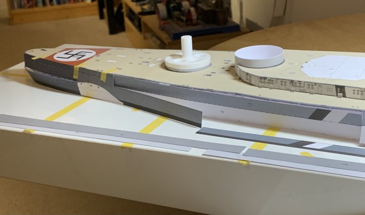
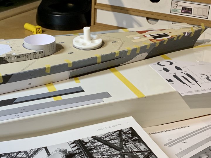
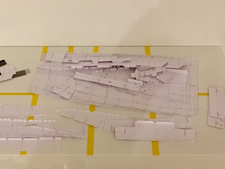
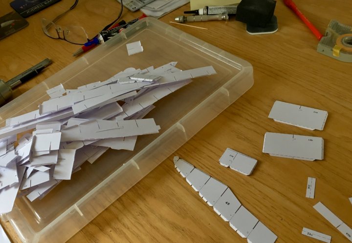
Continuing with the hull sides. Its a tricky stage on any paper ship build, as I mentioned (probably too often!) before, made worse on this one by the sheer size of the parts, the compound curves and the number of joins. Im aiming for joint line free, smooth surfaces. Anyway, Im continuing to use the technique Ive been experimenting with, to get almost invisible joins: once the lengths are confirmed, I cut the edges to be butted together at an angle; the angle must be greater than the chamfer of the blade: 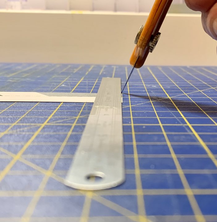 Then temporarily tape them together, and run PVA along the v shaped interface (formed by the cut) on the back side, and double it up with printer paper. The result is this: 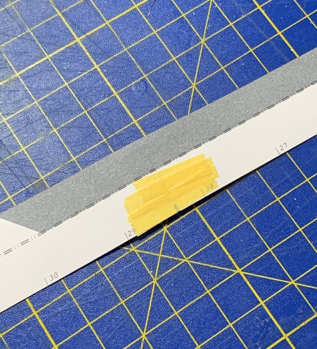 And this is the result if you use a perpendicular cut - the v is formed at the outside (corresponding pretty much to the chamfer angle of the blade) resulting in an unsightly line: 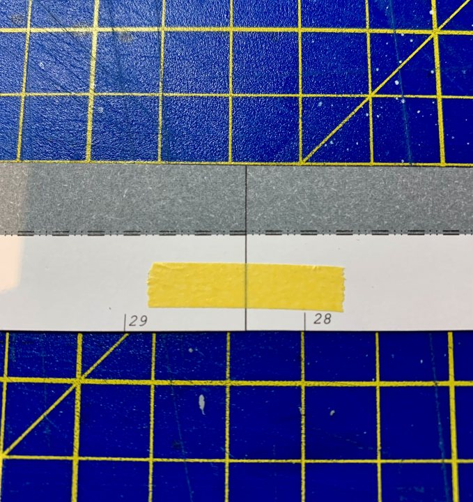 So Ive painted the edges to get rid of the white highlights, and also painted over any dotted construction lines, again I think they dont look good on a paper model. Now ready for fitting, and work continues on the bow and stern pieces, and the waterline armour belts: 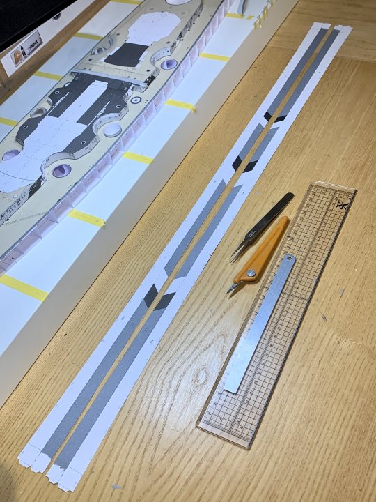 One thing I noticed is that the stern camouflage chevrons seem wrong. The width of the black and the white areas are different on the hull and in the superstructure: 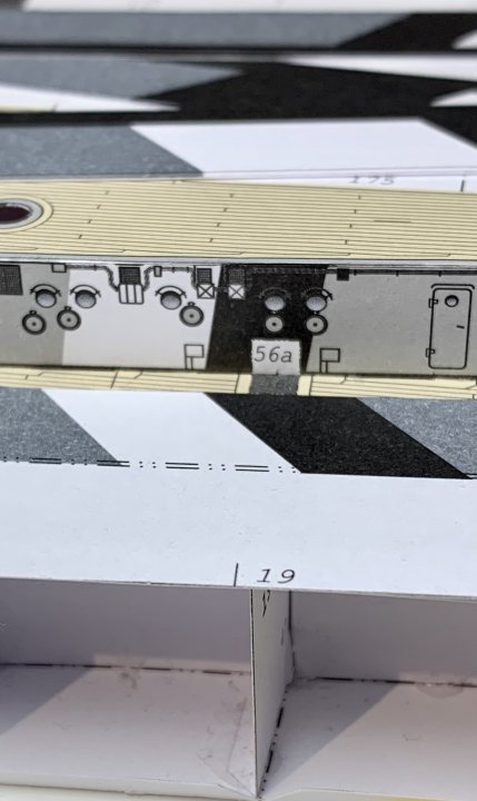 According to my reference book, they should be similar (this is the opposite side, so its a mirror image): 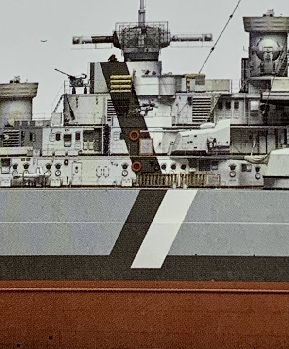 I think I read somewhere there was a colour error on this kit, perhaps this was it? Anyway, a bit of work with the airbrush should sort the widths out.
|
| Google Adsense |
 |
|
|


 Linear Mode

