


|
|
|
#81
 01-05-2020, 05:09 PM
|
|||
|
|||
|
Quote:

|
|
#82
01-06-2020, 01:48 AM
|
||||
|
||||
|
DRG - I experimented on 160 and 240-gram paper., and with the Olfa knife have to use a noticeable angle. I found I could largely keep the angle with concentration and the results were good.
For me this is a totally new technique - I must confess I have never heard of it before, or even thought of it myself - even though it is quite logical, especially with a thick blade on thick paper. Thank you. Back to your model now!!!!
__________________
The SD40 is 55 now!
|
|
#83
01-07-2020, 05:49 AM
|
|||
|
|||
|
Quote:
That's good. BTW I found the previous reference, it was from Paperlab on my SMS Emden build: Quote:
|
|
#84
01-07-2020, 07:00 AM
|
||||
|
||||
|
DRG - I have been tempted to chip in on the Bismark colour discussion you had with Dave, but restrained myself!
However, your comment that "if the model ends up looking something like the Bismarck, it's served its purpose" is 100%. People often forget that they are looking at a model only, not the real thing and that there will always be significant differences between a model and the real thing! One thing that always thumps this home to me is the question of scale colour. In a model it will never be 100%, while interpreting colours from B and W pic is hit and miss! In brief, your best guess or assumption is a good as anyone else. I posted a piece on Scale Colour in the Forum - you may find it of interest. Scale Model Colours Note the examples I gave of the Dakota - how far is the real thing in reality from the references and air force regulations? And I have seen this time and time again. I recently was on a military base - the colours of all the armour (same type) actually varied wildly and again didn't tally to references I have seen provided by "experts". I think the point is, one will never get 100% accuracy in a model. But what you will get at the end of the day is a model that does resemble the real thing! If it looks like the Bismark, then it is the Bismark. If it has swastikas, well the Bismark had those, so that's fine too! And so on! 100 people will admire the model and none will know any different. If you encounter a rivet counter, tell you them used the latest reference "Definitive Colours Scheme of the Bismark, 1999, R. Vet"! Let them go and hunt!
__________________
The SD40 is 55 now!
|
|
#85
01-07-2020, 05:33 PM
|
|||
|
|||
|
Quote:
Thanks for that, very interesting. One thing commonly done that really ruins car models is people using exact-match automotive metallic paint. The grain size is huge and the models invariably look like something out a '70's disco. The other thing on small-scale model aircraft is people insisting on using a gloss finish. They actively seem to pursue a flawlessfinish, which just serves to highlight all the out of scale surface detail, and makes a well built model look like a total balls-up. As you say though, if people are happy with it....
|
| Google Adsense |
|
#86
01-07-2020, 05:34 PM
|
|||
|
|||
|
So this time - obviously - I’m using a different method of fitting the deck. The kit has you slot horizontal tabs in the four mid-ship deck pieces into corresponding slots cut in the vertical bits of the sub-structure. This makes it impossible to pre-assemble the decks and ‘drop’ the assembly into place in one go. I wanted to match the parts’ deck planking accurately on the bench, Using the new undercut joint method, then fit it.
For the record this was the sequence: 1) Cut all horizontal tabs off. These will be replaced once complete, to support the now unsupported edges. 2) Slightly relieve all non deck printed joint lines by slightly chamfering away from the joints, in order to give as much lateral flexibility as possible. 3) Start with the rear deck, and precisely match the first two mid-ship decks to each side. Don’t secure the mid-beam lateral joint. 4) Add the second mid-ship deck pieces to the first, again precisely matching the planking, and not securing the lateral joints. 5) Drop this assembly onto the sub-structure and check fit and alignment with centreline, bulkhead edges and gun turret wells. 6) Align and secure all lateral joints. This is as far as I got:  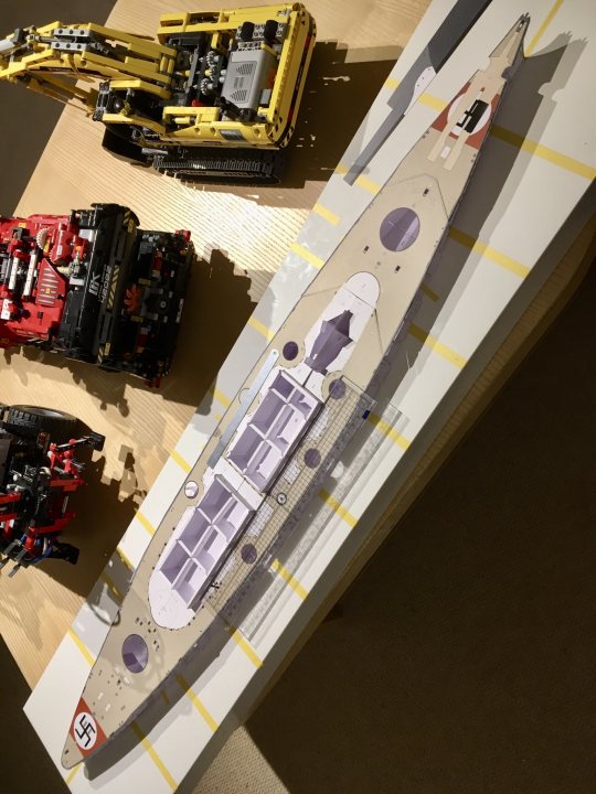 The deck is very slightly wavy, but should glue flat enough. I might make and temporarily fit the primary and secondary turret mounting cylinders, which will precisely align the deck with the corresponding wells in the hull substructure. Assuming everything aligns, I’ll then UHU the deck in place. After that, the two front deck pieces will be added. I’ve left these until last, because the joint lines are angled, and are covered by breakwaters, making alignment less critical. Any length adjustment required can be made when fixing these two pieces. That’s the theory anyway.
|
|
#88
01-12-2020, 05:22 AM
|
|||
|
|||
|
I’m a bit paranoid about fitting the deck after last time.
The primary and secondary turret mounting cylinders are a nightmare to keep round, and accurately adjusting their mounting holes in the deck is tricky with a scalpel. With this in mind I 3D printed some tapered plugs for the mounts, which keep them circular while they’re being mounted to the deck (important to avoid local warping). I also printed a pair of tapered reamers (sandpaper glued to the cone sides) to adjust the deck holes uniformly:    Result - pretty much as perfect a fit as you could get with paper, plus they will form accurate location dowels for the deck/hull side attachment:  
|
|
#89
01-12-2020, 11:44 AM
|
||||
|
||||
|
That is brilliant
awesome idea showing those plugs in action
__________________
"Rock is Dead, Long Live Paper and Scissors" International Paper Model Convention Blog http://paperdakar.blogspot.com/ "The weak point of the modern car is the squidgy organic bit behind the wheel." Jeremy Clarkson, Top Gear's Race to Oslo
|
|
#90
01-12-2020, 01:06 PM
|
|||
|
|||
|
Quote:
|
| Google Adsense |
 |
|
|


 Linear Mode

