And after the technology approved in the meantime it continued with the second
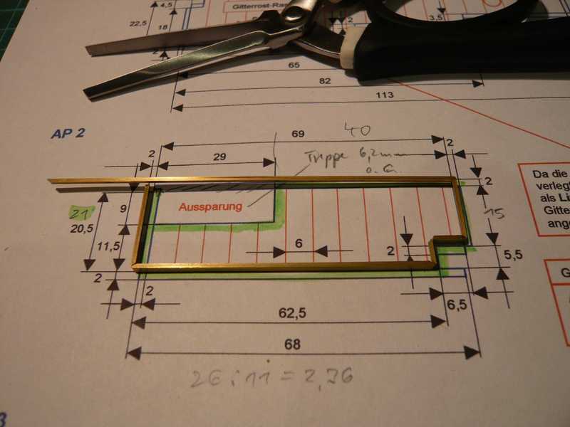
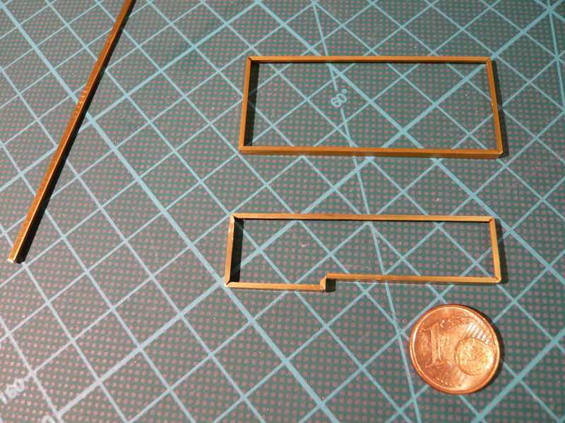
Access platform AP 2. First again the brass framework was bent from L-beam 2x1 mm.
By the
recess later stairs lead from the platform to the crawler.
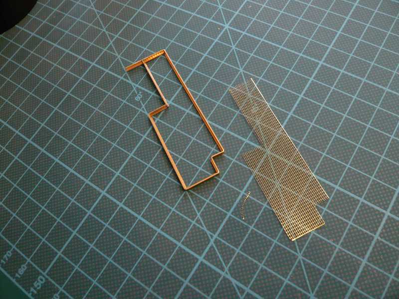
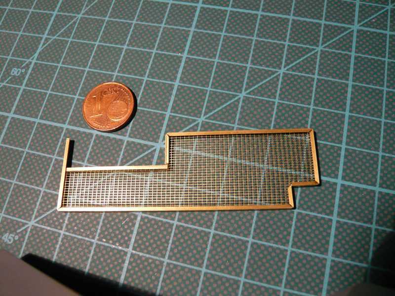
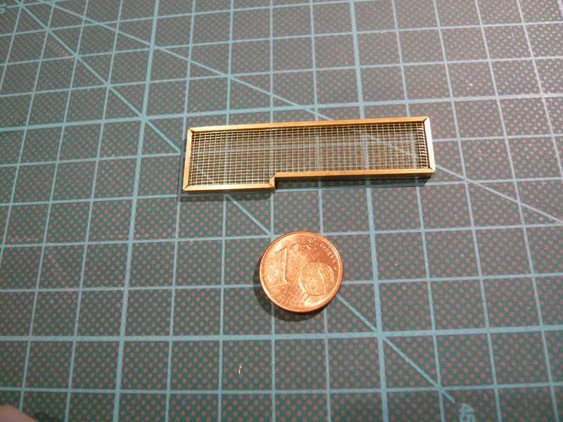
Now the PE-plate for the grating has his turn, which must be marked out and cut exactly made to measure, which not at all times is so simple.
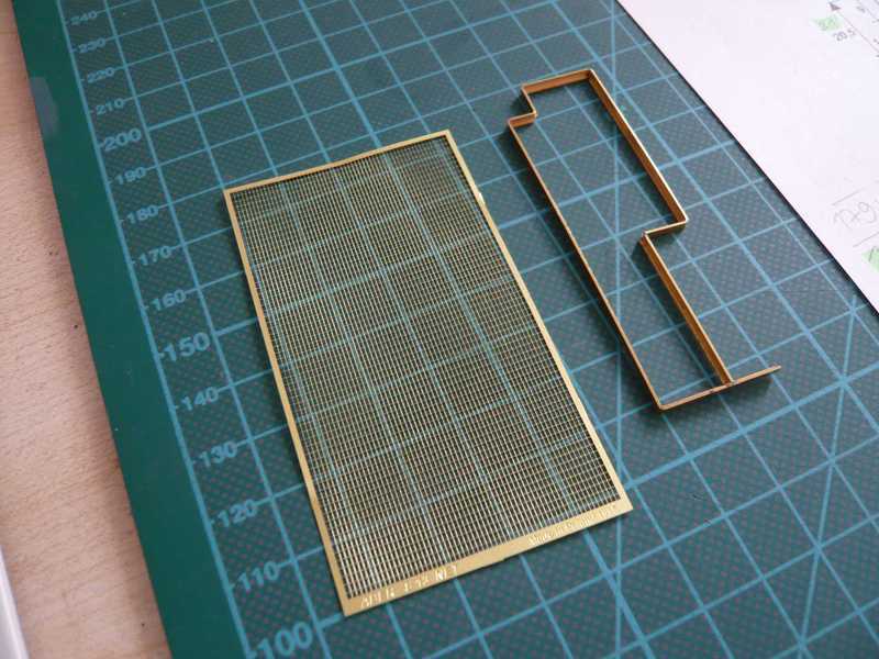
There one must look already very exactly and watch out infernally, in order to always remain when cutting in the same mesh. And if the lattice does not fit correctly then yet within the frameworks, just still another tiny mesh must be cut off.

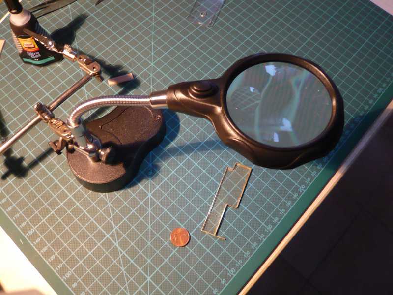
In addition one needs genuinely good nerves and above all a calm hand - and at the best still another magnifying glass, I at least. And those was genuinely helpful!

And after careful sticking of the lattice together in the framework with superglue it was then finally done.

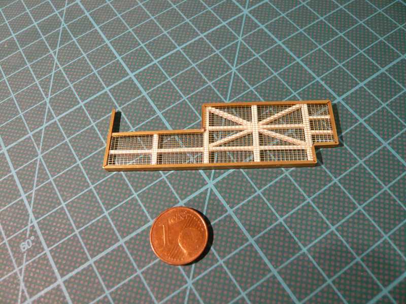
so, now the welders have made their job and installed the grating props. That were again the proven H-beams 1,5x1,5 mm as well as rectangle profiles 1,5x1 mm.
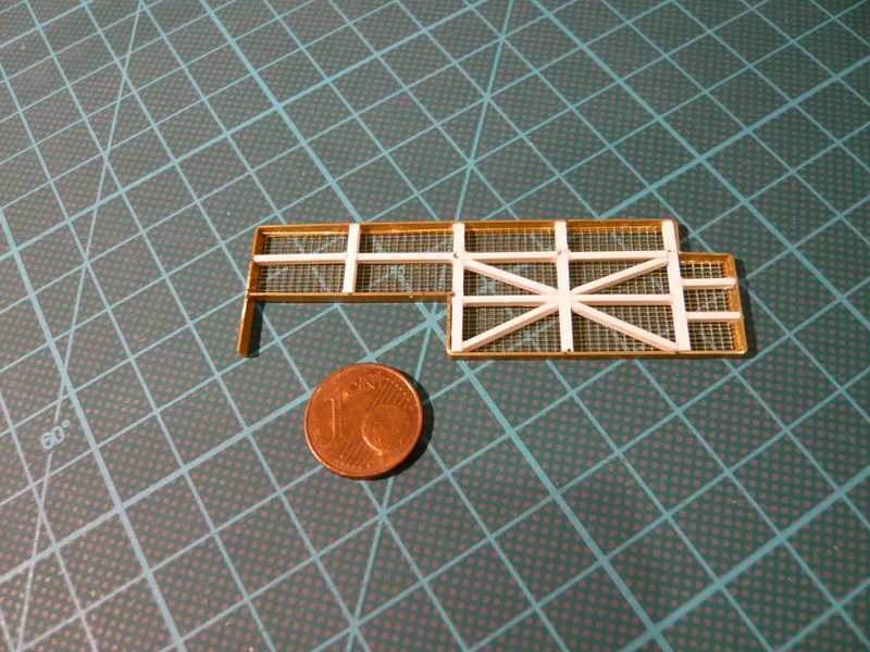
Since this lowest platform at the MLP does not have further girders, it could be actually painted.
Next now the
Access Platform AP 3 is in turn. That is the platform with important equipment and armatures for the fuel supply of the shuttle stack, in particular the
LOX & LH2 Valve Complex, lain above the platform AP 2.
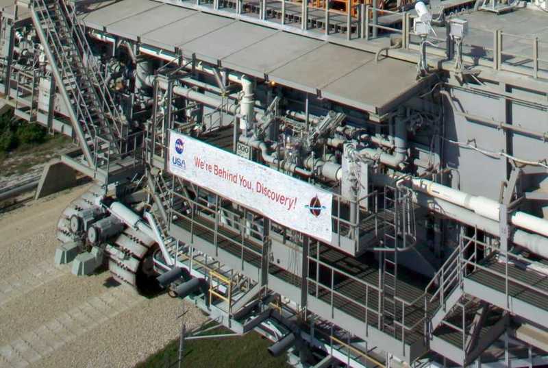 Source: NASA
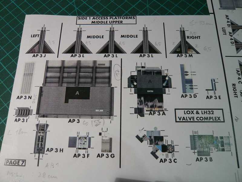
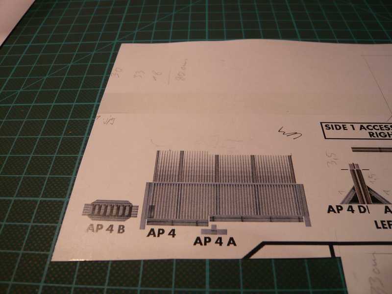
The surface area of the platform is this time fortunately only a simple rectangle, without sales or recesses. But there are above on it some difficult armatures where it guaranteed still some gives to fiddle about. On the paper sheet there is some again only hazily suggested, in particular the parts of AP 3 A-C , how one can see here.
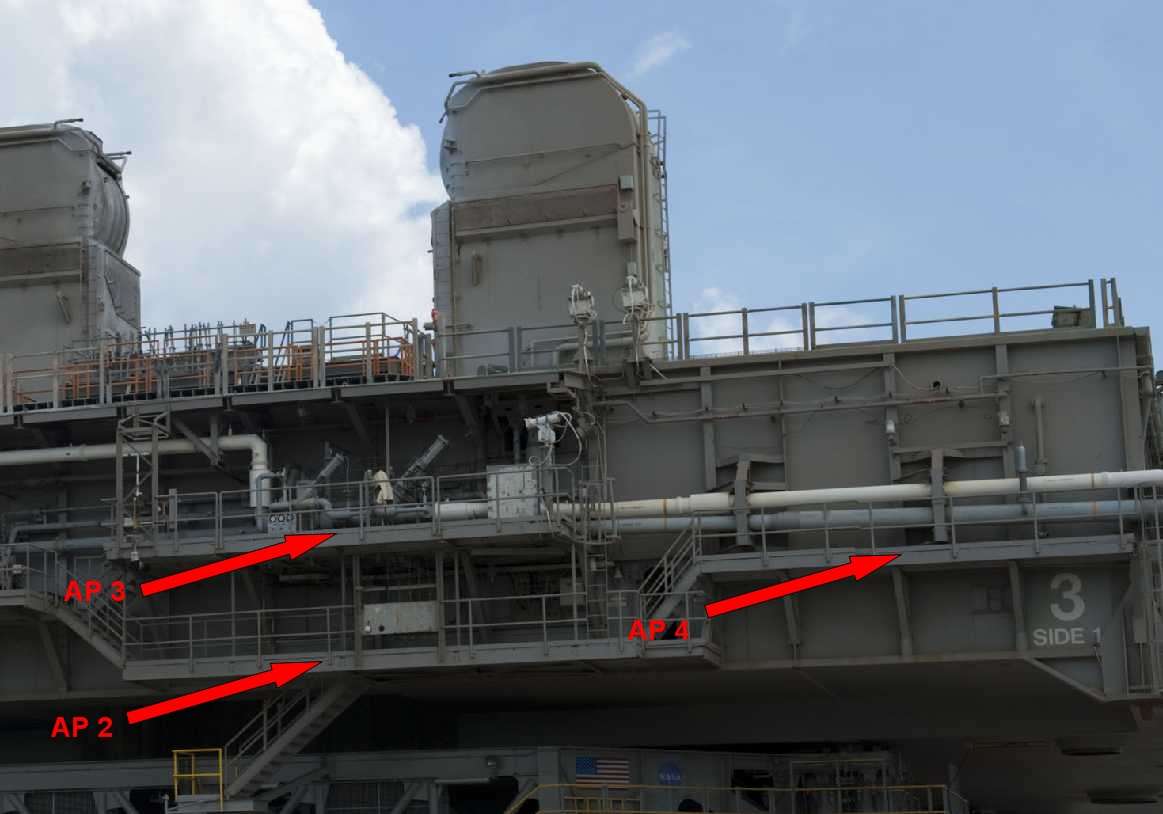
Let's see, what one can make from it. Next property I bent the frameworks of the remaining two Access Platforms AP 3 (above) and AP 4 (down) from brass L-beam.
As already said, the AP 3 is the platform with the LOX & LH2 Valve Complex armatures above the AP 2, and the AP 4 is the small platform at the right side of the Side 1 below the LOX & LH2 pipes.
 Source: NASA
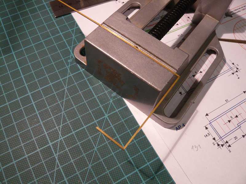
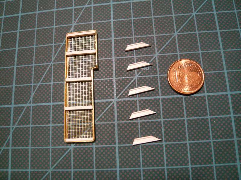
And there just a suitable rest of PE-lattices for the AP 4 was remaining, I still cut, fit in and glued together.
It continues to go with the props at the
Access Platform AP 4, with which according to the paper sheet of D. Maier five girders as platform carriers just are intended.
First these girders were cut just from H-beams(1,5x1,5 mm) and glued in the framework. Besides the preparatory diagonal bracers from I-beam section (2,5x1,3 mm) already lie, with which the platform is braced against the MLP wall.
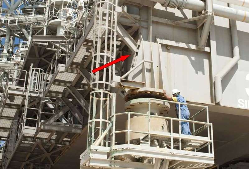
There I remembered again that with the platform AP 1 at the left side the last outside diagonal bracer could not be glued together yet, since the local Pedestal support is still missing. And that is on this side exactly the same, as one can see in the following picture. The front diagonal bracer of the AP 4 supports itself likewise against the reinforcing props of the Pedestal support off, which must be somewhat shorter therefore than the remaining bracers and therefore can yet not be installed.
 Source: NASA
