So, before the
LH2-Vent line runs now around the corner, the two supports received each on the left side the lateral oblique support struts (0,75x0,25 mm).
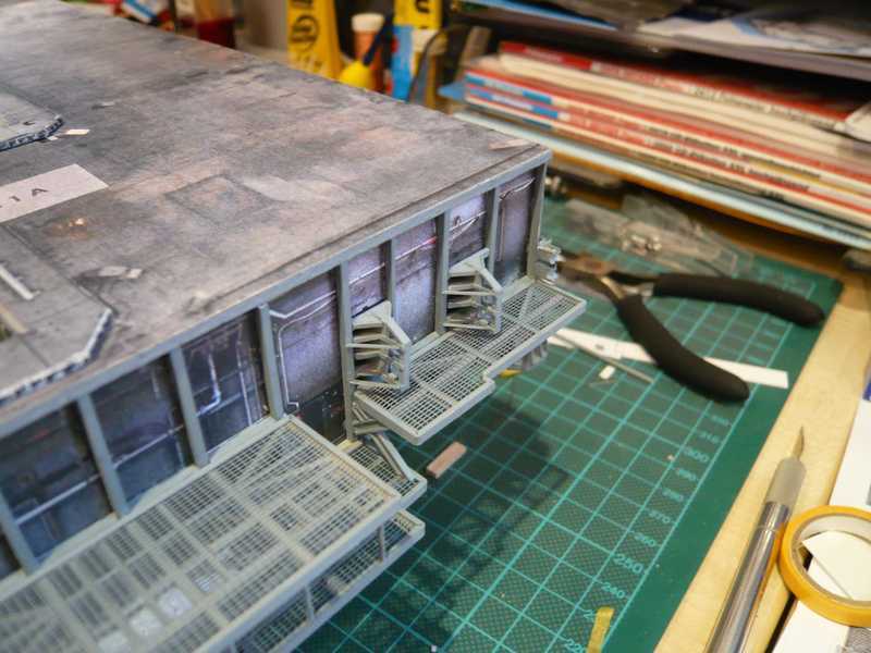
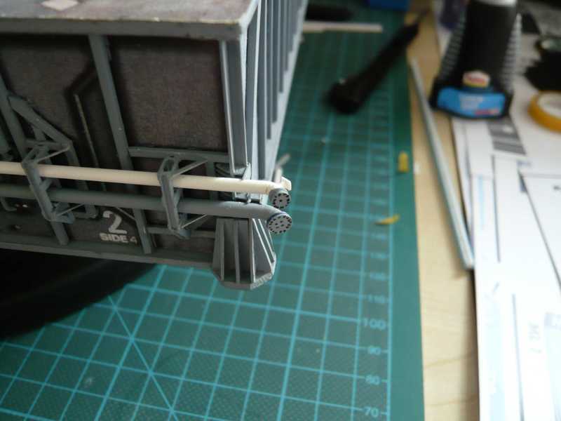
Then the segmented elbow pipe of the Vent line was prepared, which runs to the Side 1.
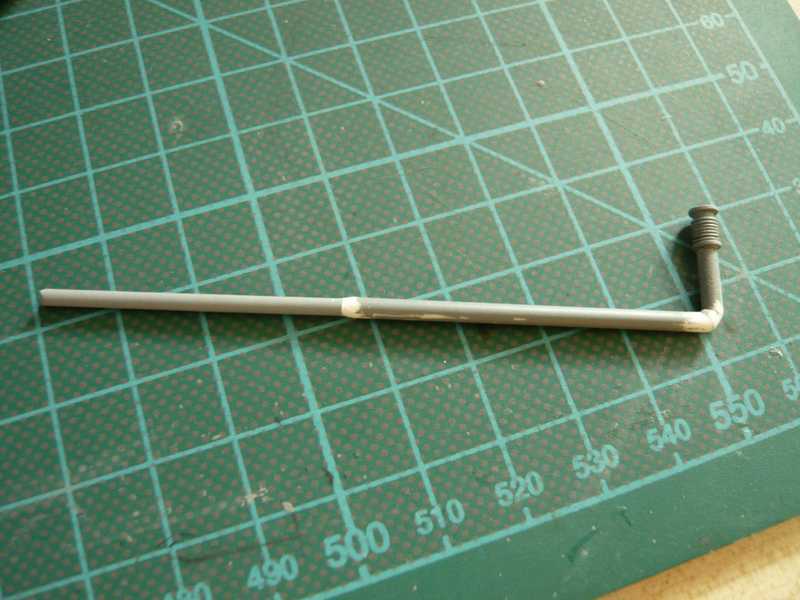
It should be noted that the Vent line is reduced immediately in front of the left support approximately to the diameter of the transfer line (see arrow).
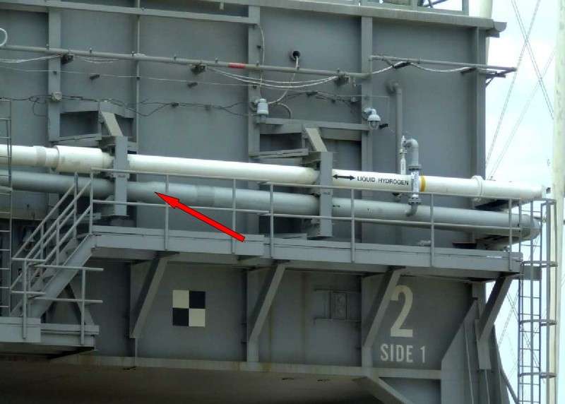 Source: NASA
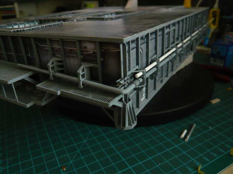
I have measured the length of the pipe to the left so that it's immediately ranging about to the support on the
Access platform AP 3 in front of the
LH2-Valve skid. After that will follow bizarre branches of pipes and valves. Therefore I will build first the valve skid outside the access platform, in order to have enough freedom of movement. Then the complete skid is to connect to the two pipes.
And now the
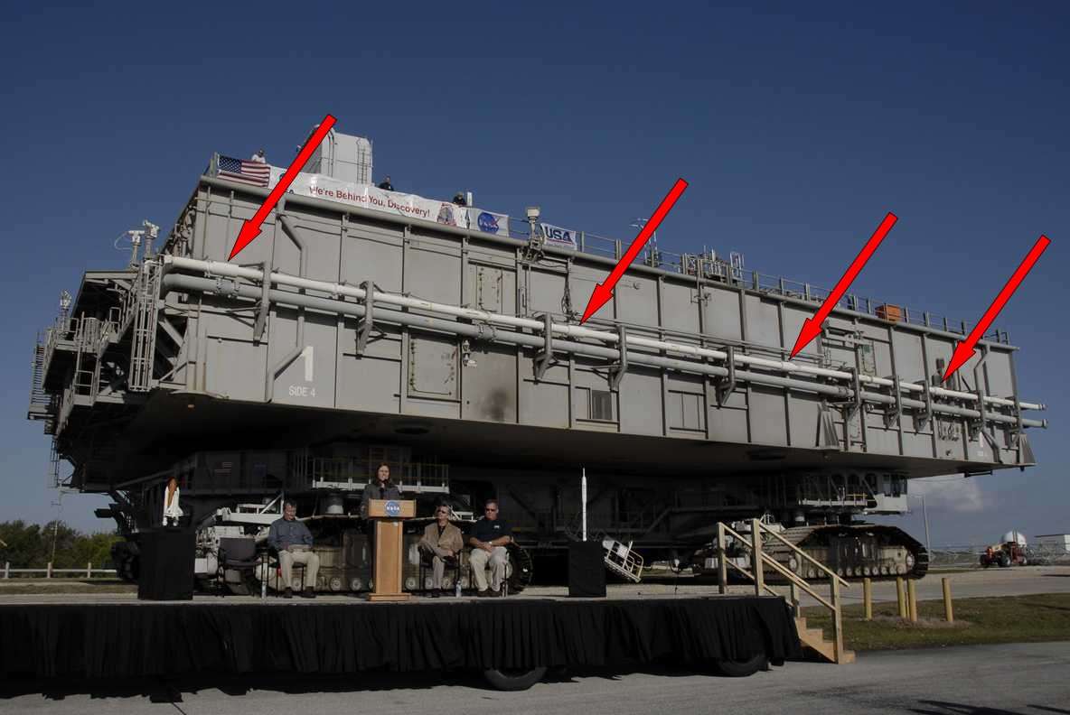
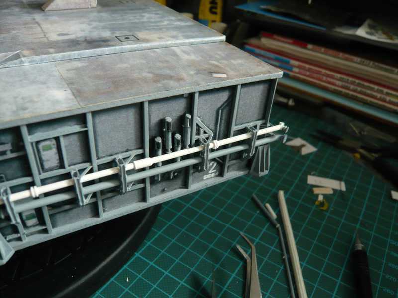
LH2-Transfer line on the Side 4 could begin next building. This pipe is thus somewhat more complicated, because it has four welded joints, which are covered with protective casings. These white casings are shown in this picture (see arrows, HiRes with double click). There are also several double rings on the line.
 Source: NASA
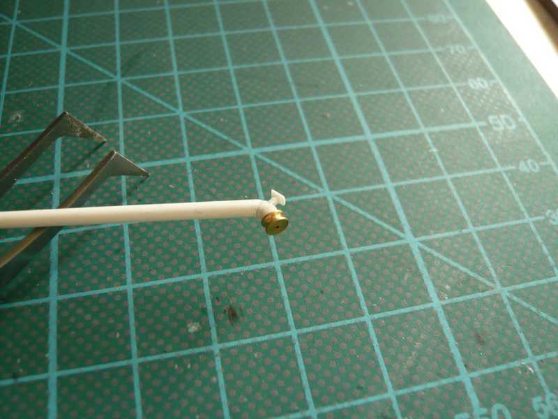
Therefore the line had to be divided into four sections. I started at the rear end, where the pipe is locked with a blind flange for what been using a brass sheave from ship modeling. The 60° elbow pipe also is segmented.
This first segment of the line was then painted.
I have wrapped the protective casings from aluminium foil and painted with white (satin).
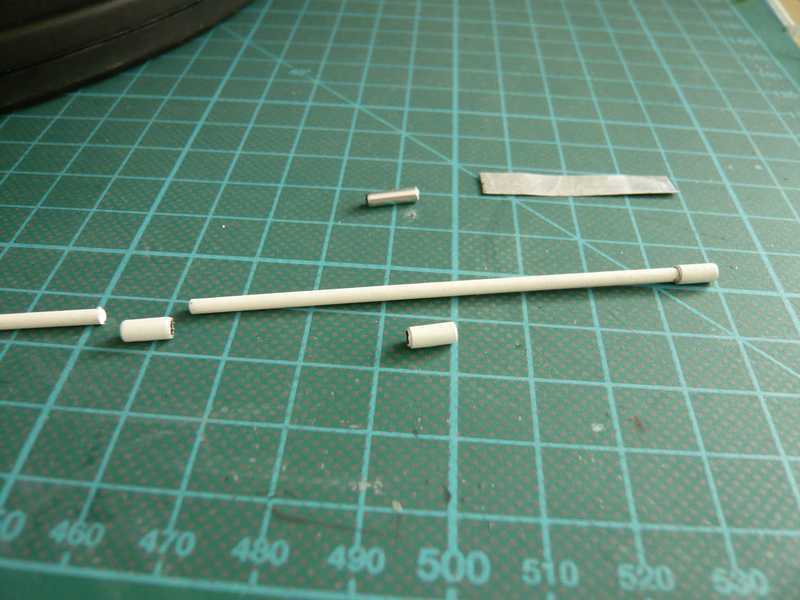
And the rings are made of strips 0,5x0,5 mm.
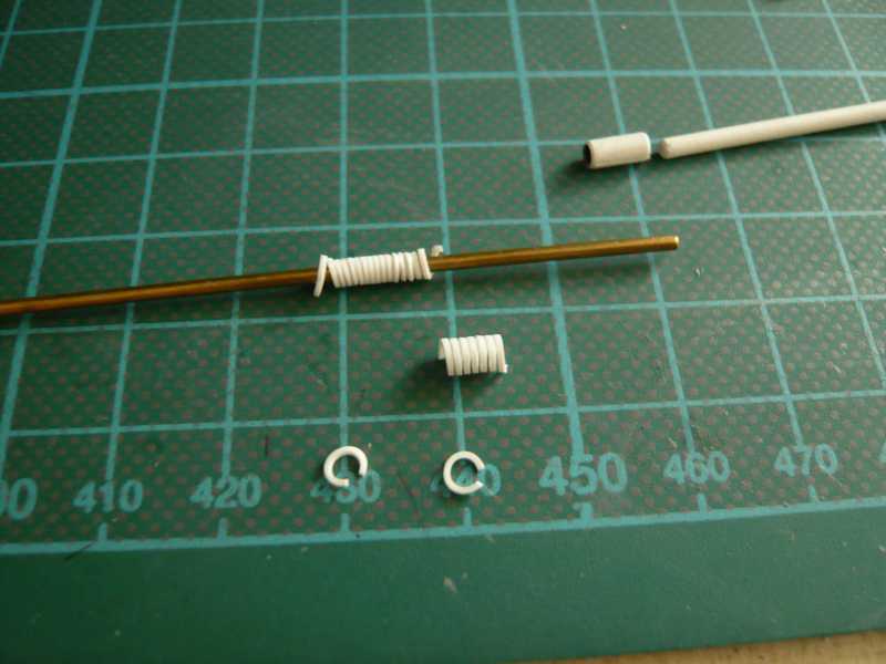
And so the first two transfer line segments are completed.
The remaining two line segments will follow next time.
